
A CEM 3312 / SSM 2056 clone using cheap PIC microprocessors
This page describes a cheap clone of the CEM 3312 and SSM 2056 voltage-controlled envelope generator chips. Both of these chips include voltage control of A, D, S and R, but both include other inputs too.
The CEM 3312 chip has a input which controls the final envelope output level. This is very handy as a voltage-controlled “envelope depth” when feeding the envelope to a filter, for instance.
The SSM 2056 chip includes a TIME input which shortens the overall time of the A, D and R stages of the envelope. Although this was partly intended as a trim for polyphonic systems, the datasheet for this device suggests that this could be fed the keyboard control voltage in a synthesizer to mimic the way natural percussion instruments typically become less resonant as the pitch gets higher.
I managed to include both of these inputs on my VCADSR. At 0V the TIME CV has no effect, and at 5V the envelope is quickened considerably.
Full details are in the datasheet below, but the envelope times range from 1mS through to 10Secs, in 4 even decades, and all control voltages run from 0-5V.
Finally, there is a digital input which selects either a ‘traditional’ exponential envelope shape, or a early-digital-era linear envelope. After this, I had to stop because I ran out of IO pins on the PIC!
Pinout Diagram

More details
- Voltage-controlled envelope generator PIC 16F684 ASM code
- Assembled HEX code from above file
- Detailed notes on the code
- Circuit Diagram
- VCADSR datasheet (includes circuit diagram and chip pinout)
Update: Current Version 7B
I’ve reworked the PWM filter to use a two-stage 4th order Bessel filter. This improves the performance and reduces digital noise on the output. I hadn’t studied filters much before, and the existing design I chose to use originally was a Chebyshev filter which has a steeper rolloff, but not such good high frequency performance. For this application, the rolloff isn’t so important, but high frequency performance definitely is.
Other changes since the previous version 7 include a TRIGGER input, so that the envelope now has both GATE and TRIGGER. It can easily be wired for GATE-only operation if TRIGGER is not required, so nothing is lost.
I also altered the TIME_CV so that it is now unipolar and only shortens the envelope. It runs from 0-5V. This is more like the original SSM2056.
Obsolete! This chip has been superseded by the EnvGen8
The new chip combines the features of the VCADSR7B and the features of LoopEnv chip too, has improved resolution, and also no longer requires a crystal. It’s an improvement in pretty much every way! Head over to the next generation Druid chips page and read all about it!.
Hi Tom,
Just a question on the two-stage 4th order Bessel filte 1khz bessel filter . If i want to fed it with 12v instead of 15v which resistors should change?
I would like to use the envelope in a 12v system.
Cheers
Tim
I have the same question but in a 5v system?
For a +/-12V supply instead of a +/-15V, you can use the circuit as-is. The op-amps won’t mind. The only sensitive part is the PIC, and its supply comes via voltage regulator anyway. So no problem – go for it!
Running a +5V supply is a completely different kettle of fish. For a start, it’s a change from a bipolar supply to a unipolar one, so for audio signals, you’ve got a lot of biasing to do. At least for the envelope, we don’t have to worry about that immediately, although you probably will have to when you feed the envelope to a VCA.
One problem to deal with is that the PIC’s output runs from very close to 0V to very close to 5V. When the op-amps are on much larger supplies, this is no problem, but if the op-amp is on the same 5V supply, the PICs input will make the op-amp clip at the power rails. You might be able to avoid this with a specific low voltage rail-to-rail output op-amp. Microchip make various – makes sense, since many people need something that works well with a PIC.
Microchip Op-amps
An alternative solution is to use a passive filter. There’s an example on Page 6 of the LoopEnv datasheet.
HTH,
Tom
Hi, thanks for such a brilliant project.
I am plannig to use it to directly “chop” the wave analog voltage and then insert the result in the Bessel filter, saving the VCA.
As my sinth goes only to C6 (2093 Hz) I think that the sampling rate is high enough.
Your opinion?
Interesting idea! If you’re going that route, you’ll have to tweak the filter’s cutoff, which was set around 1KHz, IIRC. The other point to make is that (unless your synth only plays sine waves) although the highest note might be 2093Hz, the harmonics of whatever waveform you’re playing probably go much higher. 10KHz would only be the 5th harmonic of such a note. In such a case, a sample rate of 19.5KHz is getting pretty borderline.
So, I think you need to experiment with the filter to get the right balance between VCA smoothing and high frequency loss. It’s worth a try to see what happens.
I’m just about to build this excellent looking project, just a small correction the Sequential Pro one actually uses CEM3310 for its envelopes.
Ah, I claimed CEM3312, did I? My mistake. The CEM3312 is a slightly more sophisticated chip which also includes a “Peak CV” to control envelope depth. The CEM3310 is just the voltage-controlled envelope without the depth control. Makes sense to use the simpler chip for a non-programmable instrument like the Pro-One, where the “envelope depth” control is just a pot on the front panel.
If I want to use this circuit as a CEM3310 replacement; Is there any simple way to convert the CV inputs for Attack, Decay, and Release, that are 0V to -5V according to the CEM3310 datasheet?
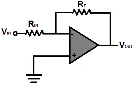
The easiest way would be to flip the 3310’s time CVs with a unity-gain inverting op-amp. That’d get them into the 0-5V range the VCADSR requires. But it’d need one op-amp per CV, plus the VCADSR chip, and its PWM filtering, so it’s going to be a “daughter board” solution, not a plugin replacement.
HTH,
Tom
Thanks for your reply! Can I just use something like a TL084? Will I need resistors, or just feedback to the positive input for each CV? Is it possible to connect the fourth TL084 OP-amp with a resistor to +15V and use it as a voltage follower to supply power for the PIC?
You’ll need two resistors (say 10K) and one op-amp for each CV. There are three that need inverting (Attack, Decay and Release), so that will use three op-amps on your TL084. It’d be the standard configuration like this:
Is it possible to use a TL084 to provide 5V for the PIC? I don’t know for sure, I’ve never tried it. It would depend on the amount of current it draws. I suspect it would probably work. If you had a voltage divider of 47K and 100K from ground to 15V, you’d have close enough to 5V at the 47K/100K junction. If you attach the last op-amp to that as a voltage follower, it might work as your 5V supply. Let me know how it goes if you try it!
Tom
Hello!
I’m trying the GATE only operation but I’m having problems with figuring out what type of signal would be the one entering through GATE.
I was trying to do it with a square signal of 2V peak and frequency around 20khz.
I would appreciate your assistance a lot.
Thanks
Hi Erick,
The GATE signal needs to be 0-5V digital pulses. It represents when a key is pressed down, so 20KHz is much too fast – no-one can press a key 20,000 times a second! The absolute minimum envelope times are 1msec for Attack, Decay, and Release, so the shortest possible envelope will be around 3milliseconds. That means gate inputs faster than 300Hz won’t really work at all. In practice, a few 10s of Hz would be a better upper limit.
I hope this gets you running!
Tom
I have a couple roland synths with broken IR3R01 envelope chips and I’ve despaired of finding enough replacements…. is it possible to replace them with this relatively easily? The CV ranges appear the same but I’m wondering about the shape … I’d likely have to replace all of them i suppose?
-dk
Hi Tom,
For modular system builds, do you recommend protecting inputs from voltages higher than +5? Would using 5v zener at each input suffice?
Many thanks for your great docs.
C
Colin,
For input protection I recommand a diode clamp. Use fast diodes like Schottkeys. (I use BAT85s for most of my clamping needs)
https://i.stack.imgur.com/oKptw.png
BTW, awesome chips, Tom!
Hi Tom,
dumb question time! Am I right in assuming that gate and trigger inputs can be used simultaneously as in my old SH 09?
Thanks
JIm
Yes, they can. If you’ve only got Gate available, you should tie the two inputs together. The VCADSR starts the envelope when the TRIGGER goes high, and goes to the Release stage when the GATE goes low. So it doesn’t work with nothing connected to TRIGGER. It’d be a bad idea to leave the pin floating anyway, so it’s kind of a moot point…
T.
Hi there,
Could you please let us know the details on how to build a replacement for IR3R01 using the VCADSR Envelope Generator 7B chip ?
Thank you
Hi Stephen,
Thanks for your comment. It’s not immediately straight-forward, but I’ve been asked about this on a few occasions, so I’ll give it some thought and see if I can put an article together about it at some point. The biggest problem is that the VCADSR needs a filter after it to turn the PWM output back into an analog envelope.
Regards,
Tom
Hi Tom,
Great !! We are waiting for your research.
Thank you
Hi Tom. I have to very interested in one solution for replace the IR3R01. When you think you can have a solution?
Best Regards.
No time soon. It’s not a priority for me. Sorry.
Hi Tom,
I’m thinking of using this design as part of a project for uni. I was wondering about the clock in pins as I have an Arduino Mega as the main microprocessor for my design. This has a maximum clock output of 16MHz whereas this chip stated a clock value of 20MHz. Would it therefore work with my system or is there any way this could be adapted to run at a slower clock rate.
Regards,
Jack
Sorry, I’m not quite clear what you’re proposing – are you thinking of clocking the PIC from the Arduino Mega? The PIC’s clock inputs are expecting a crystal rather than an external clock, so it might not work, but that wouldn’t be a big change to make to the code. You’d just have to tweak some CONFIG words.
Moving from a 20MHz to 16MHz clock rate would just slow the envelopes down by 20%. At the short end, that’s not really noticeable (1msec and 1.2msecs are both really short!) but at the long end, it makes more difference (12.5 seconds is quite a bit longer than 10 seconds).
HTH,
Tom
Hi
I’m currently designing an analogue Synth using op amps and inverters as oscillators etc.
Would this work in any way with my piece? I am using DC currently but I may have to switch to AC
Thanks
Joe
Yes, this would work. You’d be better off with the updated version, the ENVGEN8:
EnvGen8 product page
This new version doesn’t need a crystal, which makes life simpler, and also uses an on-chip DAC to produce the output, which reduces the need for filtering compared to the PWM output on the VCADSR 7B. It could be run with just a 5V supply. There’s an example schematic in the datasheet, using the chip with the AS3360 Lin/Log VCA.
Hi Tom,
I’m another one of those (oh shit I need another IR3R01) people.
Did you get anywhere with your build/blog?
I know I’m not the only one who would be interested in a clone.
Regards,
Josh
Hi Tom,
I am also have a desire for a IR3 adsr, I don’t mean a pin for pin clone but just the output.
Cheers
Dennis
If you don’t need a pin-for-pin clone, what’s the difference between the IR3R01 and any other envelope generator? Why not use a AS3310 or an ENVGEN8?
T.
Hi Tom,
Cause I am irrational and paranoid 😉 Like most of us I guess.
Cheers
Dennis
I suppose I was hoping for a *technical* reason!!
Did you reverse engineer a specific adsr’s slope? If so, would it be useful to provide you with a IR3R01 for closest possible approximation? I don’t have one now but can look for it. I am trying to recreate JP8 sound, I want to get as close as reasonably possible. All modules are reversed engineered but the IR3R01.
If you can get hold of one and get it to me, I can copy the curves into a chip like the ENVGEN8. That part is no problem. But in truth, pretty much any analog envelope generator is going to follow a capacitor’s charging/discharging curve. There’s only so much you can alter.
Both the range of available times and the output curves are set up by look-up tables in the ENVGEN8, so you can modify those to taste, or to match up with some specific previous chip. This is what J-P Desrochers did some (many) years ago turning the VCADSR7 into a clone of the Moog 911 modular envelope generator.
By coincidence I just read your article about the 911 so I understand what you are doing now. Not fully yet though, how do you deal with the timing, interpolate or stored values for a range of timings? There is undeniable a difference between synth env outputs but maybe that has got more to do with the surrounding supporting components. In that case we should get somebody willing to analyze the JP8 curves. Unfortunately I sold mine last year because of a temporarily empty stomach ;( I know someone with a JP8 that is technical enough to do this, not sure if he is willing.
I know the JP8 well enough to hear if the ENVGEN8 will do, I will buy a few so that I can proceed now and will hunt for the JP8 data till I have it 😉
btw Did you got significant different values for the 911?
I don’t have any measurements for the Moog 911 version. You’d have to ask JP Desrochers.
BTW, did you see this: A DIY Jupiter 8 clone. The only bit they didn’t clone was the envelopes. They used my VCADSR7B instead. So far I haven’t seen anyone complaining…;)
https://www.sequencer.de/blog/jupiter-8-cloned-but-4-voices-at-800e-diy/23205
Yes tiergrinder inspired me to go for it too, it is amazing how close you can get with modern components. Even if it is not exactly the same, it still sounds fantastic. I hope I can nail it at least as well. I just finished this one http://www.anatal.io , I want to use it to create a modular JP8. Have no clue how long this is going to take.
… ps, apologies I did not read your answer well enough, you store both times and curves, so that answers my question. Great! What is the resolution of the timings? I suspect the first few milliseconds of the attack and the decay are what distinguishes envelopes musically wise.
There are 256 different time settings across the Attack/Decay/Release controls. This is finer that you can detect. Each setting can be defined however you like, so you can tweak the control response to give a equal-octaves or equal-decades character, or do something else more personalised. ENVGEN8 uses a equal-decades response, but modified with the addition of a shallow linear slope so that the very shortest times don’t take up quite so much knob travel. This is a solution that has evolved over the years I’ve been working on envelope generators and seems to give a good “feel”.
I am curious how it feels and sounds, just ordered a few, thanks.
Hello TOM,
I recently bought at Juno 6 and i have the Env gen not working, so I ended on your website and i was wondering if the EnvGen8 would work as a replacement for the ir3r01, I don’t mind not having the same specifications in term of env timeetc, I am just trying to find a replacement that could make my Juno getting back to life.
I was thinking about buying this envgen8 but i am wandering if it would work on my Juno if I make it fit ( for example if i try to change the pin number so that it can fit into the juno)
I don’t know if I am really clear but I was reading the thread and there was no answer yet.
I am looking forward to get an answer from you.
Cheers,
Val
Hi Val,
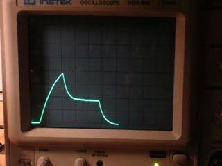
Someone else has asked about this recently too. I’ve never had a synth with an original IR3R01, so I’ve never been able to test any replacement, but I’m hoping we can work together and get a functional replacement. If I had specific questions about voltages in the envelope circuit, would you be able to take some measurements for me? Do you have an oscilloscope?
Thanks,
Tom
Hi
I am researching the IR3R01 chip to work out how it works and achieve a drop in replica, for Jupiter 8 and Juno 6/60 users. Whilst the original looks to be based on the Jupiter 4 ADSR which is complex and uses oscillators, it may be possible to develop Tom’s design. I have started a post on my website to record progress, a test harness for the Jupiter 8 use case is the next step as we need to find out how the Modulation pin works. Small SMD parts will be needed to achieve a 16 pin DIL foot print.
https://amsynths.co.uk/2019/05/09/roland-ir3r01-clone/
Any ideas, measurements in the real world are very welcome! I have a Juno 60 which I taking envelope curve measurements from but I expect them to be accurate exponential.
I’ve been thinking about a similar thing, Rob, so if there’s any help I can offer let me know. I don’t have an IR3R01 chip to test unfortunately, but if you can find out more about it, I can tweak the time range and perhaps the curves to better match the original Roland chip.
It seems like there’s an increasing need for these for repairs.
Hi Tom,
Thanks for the offer of help! I do have a Juno 60 as a test bed, next step is a Key Follow Test harness on breadboard, so I can see whats happening in the Jupiter 8 and the IR3R01 Modulation Pin. The PIC is available as 16QFN, so there is a possibility to get this onto a 16 pin DIL PCB! ….Rob
Excellent. BTW, I recommend basing the clone on the newer ENVGEN8 code rather than this one, Rob. The ENVGEN8 uses the 16F1764 which has a proper 10-bit DAC output and you can use the DAC reference voltage for level control, which means you don’t lose any resolution when you decrease the level.
Hello robert, if you need some measurements and pictures of the behavior of the IR3R01 in a JP8 I actually have a JP8 and an oscilloscope, so if i can help I would love to.
Cheers,
Val.
Hello TOM, sorry for the late reply, I didnt get any notifications so I thought you havent seen it yet, Yes i do have an oscillator and I have some IR3R01 in stock, I can take some measurements if you need.
I can also send one to you if it could help some others that needs this chip in the future.
I know that there is a lot of Junos and Jupiters that are waiting for this IC to get cloned so I could send you one if it would help everyone.
Here is my mail adress so that we can get in contact easier and faster : [email protected]
Cheers,
Val.