
I’d like to share a couple of things I’ve had kicking around on my desk for a long while. They also show a couple of ways to use vactrols. One is a simple optical tremolo, presented below, and the other is a modulated delay effect.
StompLFO Optical Tremolo
One very simple way to produce a volume change with a vactrol is to connect it up as a voltage divider. When the vactrol’s LED is on, the LDR’s resistance will drop, reducing the level. When the LED is off, the resistance goes up and the full signal (Ok, very nearly the full signal) goes through. This gives us a volume control that can be remotely controlled by the LED current.

So what value would we need for R3? We could just try a few on the breadboard and see what works best, and that’s a perfectly valid approach. But we could also get some data about our vactrols and work out roughly where we need to start. The StompLFO’s output pin can only provide 20mA to power the LED, and perhaps we don’t want to draw all of that. The Xvive VTL5C3 datasheet and VTL5C1 datasheet give a 2.5V figure for the forward voltage at 16mA current, so let’s go with that as a maximum.
We have a 5V output from the StompLFO, and we need a 16mA current, so we do the usual calculation to find the current limiting resistor we need for the LED. First, find the voltage across the resistor.
Resistor voltage = Input supply voltage - LED forward voltage
Resistor voltage = 5 - 2.5 = 2.5V
Then we can use Ohm’s law to find the required resistor. V=IR, so R= V/I, and we have 2.5V and we want 16mA:
R = V/I = 2.5 / 0.016 = 156 Ohms.
The nearest E24 value is 160R, but 180R is a lot more common. That’ll give us a current of 13.8mA, so that’s fine. For the FilterFX, I used a 470R resistor which gives a 5.3mA LED current. We could split the difference and use 270R for 9.3mA current.
Once we have a safe resistor value that protects the vactrols and the StompLFO chip, we can do a little test on the breadboard. First we test the LDR’s resistance when it is off. Then we run the vactrol’s LED through a resistor from a 5V supply so we can test the LDR resistance at the maximum LED current. The StompLFO output will vary between these two extremes. Here’s what I found testing three Xvive vactrols of each type:
| 180R Resistor, 13.8mA LED current | 270R Resistor, 9.3mA LED current | 470R Resistor, 5.3mA LED current | LED off | |
|---|---|---|---|---|
| VTL5C1 A | 450Ω | 600Ω | 870Ω | 12MΩ |
| VTL5C1 B | 1.2KΩ | 1.5KΩ | 2.2KΩ | 16.8MΩ |
| VTL5C1 C | 420Ω | 550Ω | 850Ω | 18.7MΩ |
| VTL5C3 A | 640Ω | 900Ω | 1.5KΩ | >20MΩ |
| VTL5C3 B | 790Ω | 1KΩ | 1.8KΩ | >20MΩ |
| VTL5C3 C | 520Ω | 700Ω | 1.2KΩ | >20MΩ |
Incidentally, if you try this you’ll notice that the dark resistance of a vactrol continues to increase for a long time after the LED goes off. That’s normal! It’s just how they work. At some point we can simply say that the resistance of the vactrol is “very big” and we don’t really need to know much more about it. The biggest resistance range on my meter is 20 Megohms, so once it goes above that I can’t measure it, and I don’t care anyway. This is the reason you quite often see a resistor in parallel with the LDR of a vactrol – it gives us a known maximum resistance, for occasions when that is important. The FilterFX was such a situation, since the maximum resistance sets the lowest possible filter frequency.
Now we know better what resistance we will get from our vactrol, we can choose what value we need for R3. Running the vactrol with a 270R resistor, we get an LDR resistance of roughly 1KΩ, give or take. If R is 10KΩ, then it cuts the signal to 9% (1 / (10+1) = 0.0909) as a worst case. That’s -20dB. We probably want a bigger reduction than that, so we should boost R’s value. 47KΩ would give us around 33dB of cut. That’s pretty good.
What happens when the LED is off? Say the LDR resistance has gone up to 1MΩ. We know it will go a lot higher, but we don’t want to wait for ages, so we’ll use a conservative figure. 47K over 1MΩ gives us 95% of our signal, a mere 0.4dB reduction.
Now, we need to turn this vactrol-controlled-voltage-divider into a proper effects circuit. We can’t connect an output to it directly because it will interfere with the voltage divider values, so we need to follow it with a buffer. We can also add a DC blocking cap, a volume control, and a resistor to protect the op-amp in case the output gets shorted. That’s all the standard “output stuff” done!

Adding an input buffer
Ok, let’s look at the input. We need an input buffer to provide a nice high impedance to any other source we plug in, and since Tremolo tends to reduce the volume of the signal (you’re cutting some of it away) it might help if that buffer had some gain available. Again, this is all standard stuff, so we can cut-n-paste some bits in. I used a stage like this at the front of the Hard Bargain pedal.

The gain resistors are chosen with moderate values, not too large to generate a lot of noise, but not too low that they use a lot of current. We don’t need huge amounts of gain (this is not a drive pedal!) so we go with 10K and 1K+47K preset. The gain equation for the non-inverting opamp is:
gain = 1 + ((PR1+R6) / R5)
At max gain that gives us:
gain = 1 + ((47K+1K) / 10K) = 1+4.8 = 5.8 = +15dB
At min gain that gives us:
gain = 1 + (1K / 10K) = 1+0.1 = 1.1 = +0.8dB
That is basically it for the audio path, which is great. One dual op-amp, well buffered in and out, and not much going on. That makes for a nice quiet pedal that will behave well with other things. We’ll look at a few tweaks later, but first let’s take a look at the StompLFO that’s going to control this.
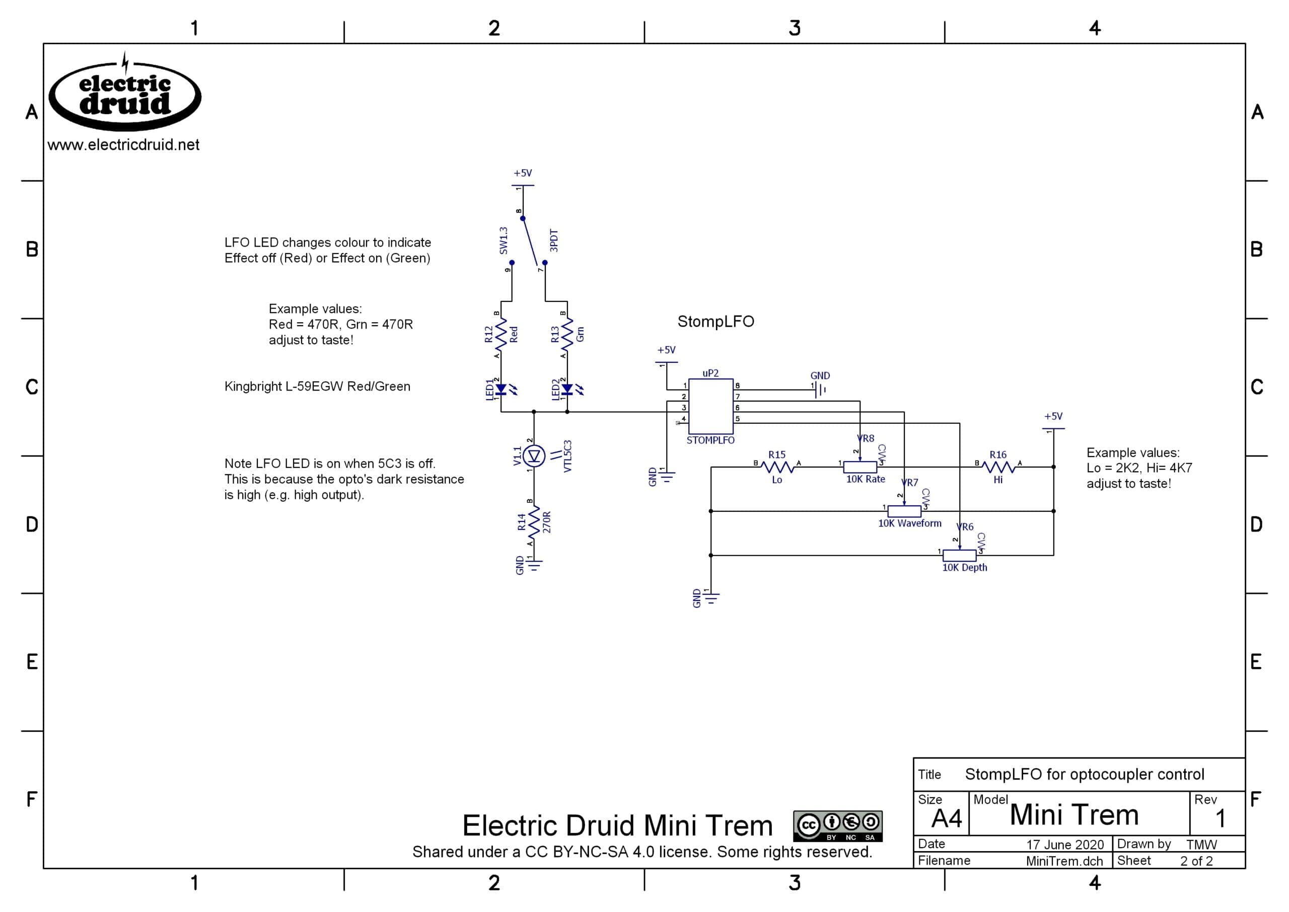
The StompLFO control circuit
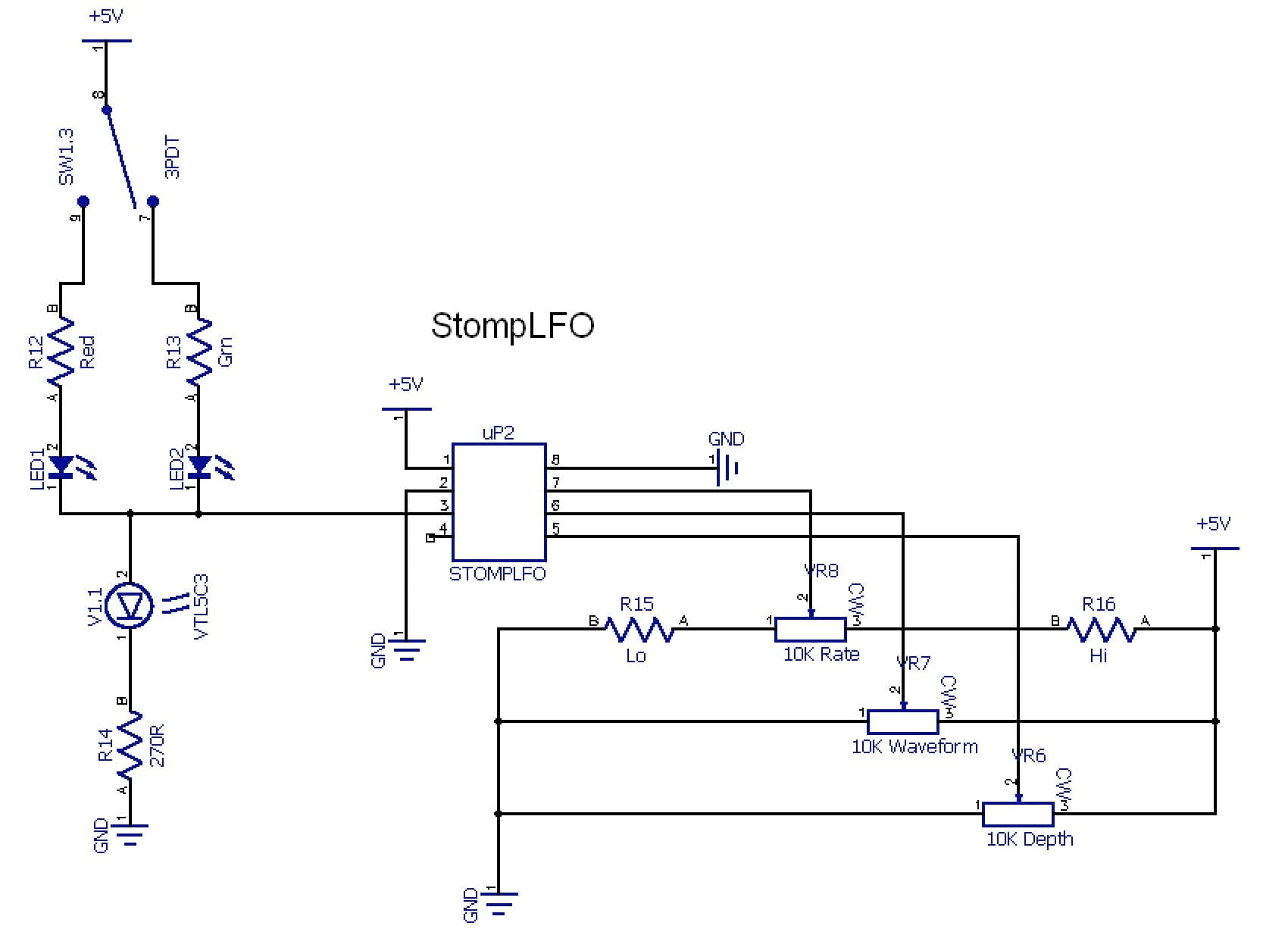
The StompLFO needs solid voltages to its four CV inputs or it’ll get all upset and do weird stuff. We definitely need pots for Rate and Depth. Offset CV (pin 2) doesn’t need to be variable. With a Tremolo, we want the modulation to work “from the top down”, e.g. more modulation depth cuts deeper and deeper into the signal level. Since we get the most signal with the LED off, we can do that by tying the Offset CV to 0V, the inverse of what we might expect. The Waveform CV I leave up to you. When I tried it, the waveforms I actually liked best were the classic tremolo waves of Triangle and Sine. Triangle is good, but Sine gives you that vintage “throbby” sound. Square is good for that choppy “Helicopter Trem” sound. If I was to hardwire one wave, it’d be Sine. However, putting a control on it doesn’t rule anything out, and it gives you all the other options for more experimental occasions, so it’s your choice.
In a similar vein, you can add resistors to either end of the Rate pot to limit the range to whatever you regard as “sensible” or, at the loss of a bit of control sensitivity, you can leave it covering the StompLFO’s full range from 0.05Hz (once every twenty seconds!) up to 25Hz (once every forty milliseconds!). Honestly, for a tremolo I do recommend trimming it a bit – the full range is ridiculously wide for this application! On the schematic above, I’ve left resistors marked “Lo” and “Hi” in place to do this.
I’ve done one little fancy tweak here, which is to use a bicolour common-cathode LED for the bypass and LFO LED (e.g. LED1 and LED2 are in one package). The idea is that it flashes at the LFO rate all the time, and it changes colour to show whether the effect is off (red) or on (green). I’ve shown separate resistors for each colour so you can adjust the brightness of each independently. Start with 470R for “Red” and “Grn” and then adjust to taste. The bicolour LED is connected up to the 5V supply, so it is on when the StompLFO output is low, and it goes off when the StompLFO output is high, the opposite of the vactrol’s LED. This also means the two LEDs (one bicolour one, and one in the vactrol) are never on at the same time, which limits the current the StompLFO has to deal with.
Tone tweaks
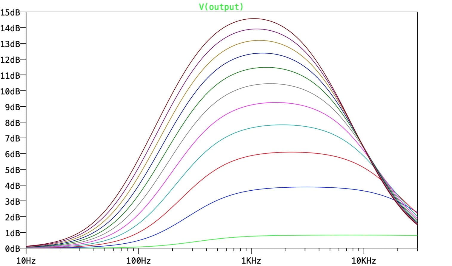
I mentioned that we could tweak the audio path a bit, so let’s look at that. The input amplifier we have currently gives us a full range audio signal. The gain has no upper limit imposed. This is bad practice, since it means we are also applying gain to any ultrasonic noise that might have been fed into the pedal from some previous device, or any radio frequencies that might have got picked up from somewhere. A better idea is to limit the gain to only the bandwidth we care about. We can add a capacitor C7 across R6/PR1 to do this. Since PR1 is variable, the cutoff frequency of the filtering produced by this will also be variable, but we can use this to our advantage.

We also need to think about the lower limit of frequencies. At the moment we apply the gain down to DC. Again, we don’t really want to add extra gain to any mains hum that is coming in, so we’d be better limiting the gain below 100Hz or so. That won’t really affect the lowest guitar notes, but might help cut hum and any subsonic thumps (people bumping stuff, for example) a bit. For this we add a cap C6 below R5. This also allows us to connect this point to Ground rather than Vref, since now the cap blocks the DC level.
If we use a relatively large value for C7, like 1n (22-100p is more common in this position) then as the gain is turned up, the high frequency rolloff moves down significantly into the audio range. Coupled with the bass roll-off provided by C6, this gives an increasingly midrangey sound as the gain goes up. This deliberate frequency response shaping gives the pedal a bit of character and makes it sound more 60s.
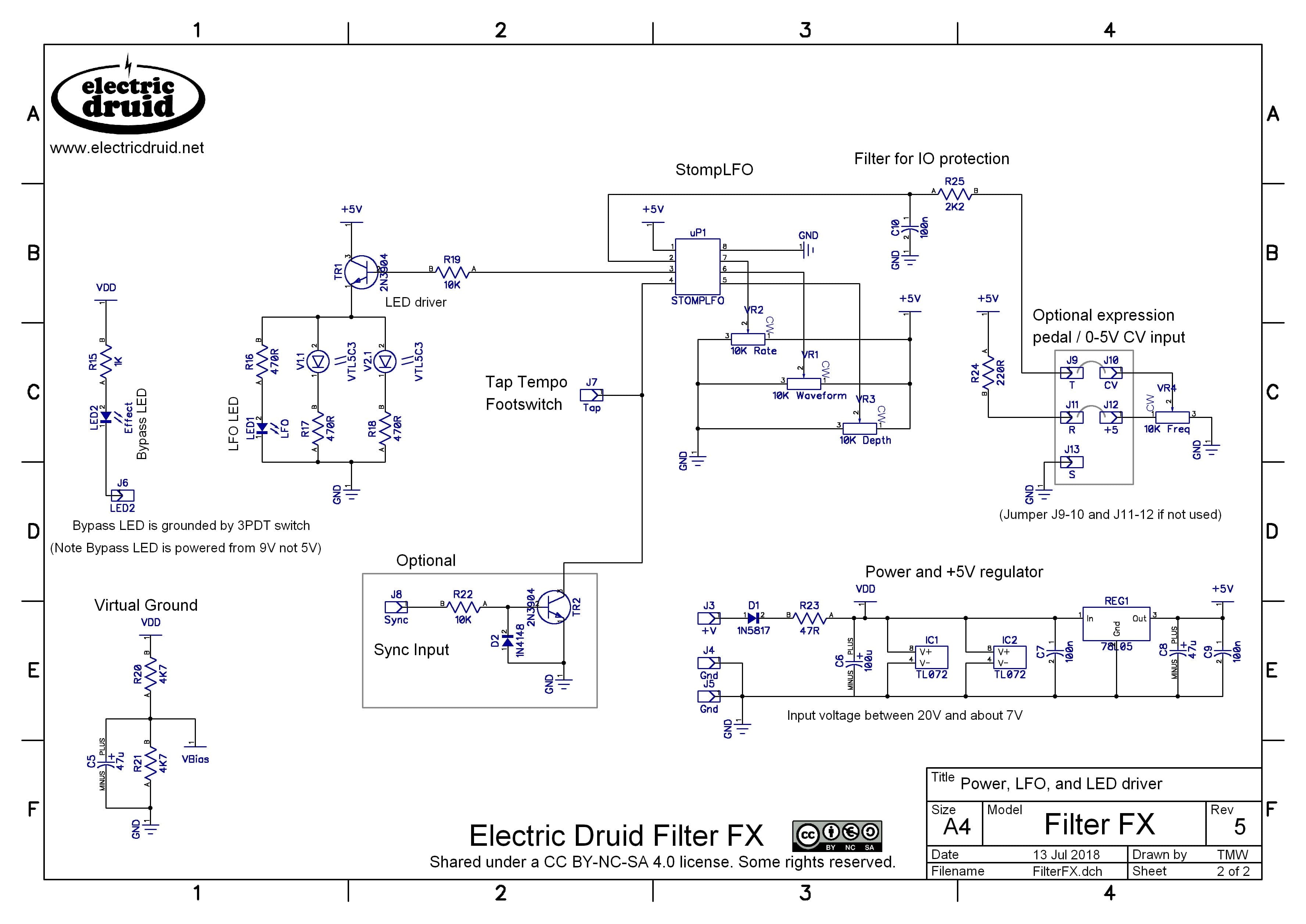
Ok, so what does our final circuit look like. Here it is:
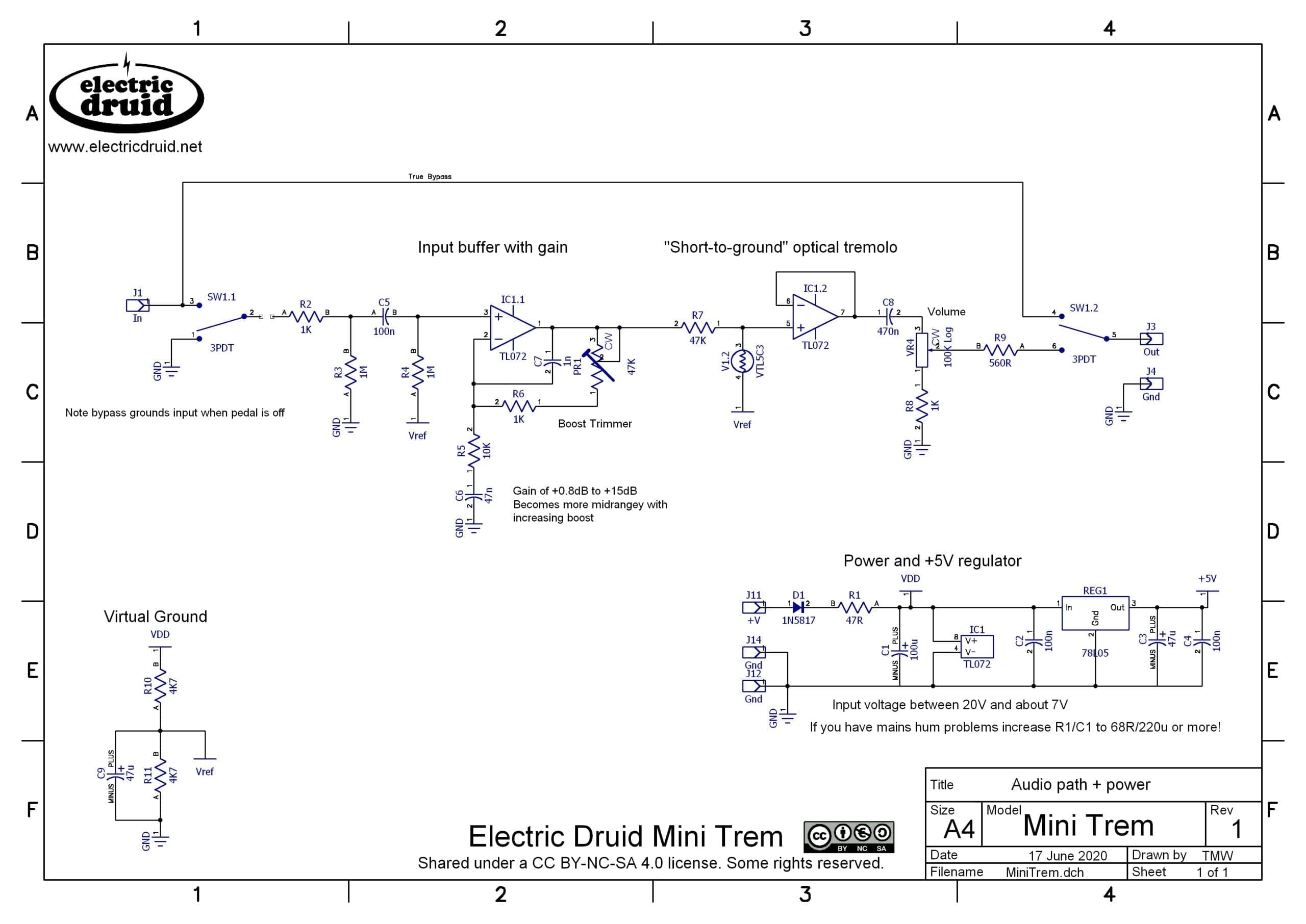
The only things we haven’t mentioned yet are the typical stompbox power elements, shown in the bottom right and left of the first page – D1 to provide reverse polarity protection, R1/C1 to provide some power filtering, and a 5V regulator to provide power for the StompLFO. We also have R10/R11/C9 to provide our midpoint bias voltage, Vref.
Going Further
Since the StompLFO has a tap tempo input on pin 4, you can easily add a momentary SPST switch to ground to add a tap tempo feature. It is also possible to add a Sync input circuit so that the LFO can be synchronised to other gear with clock pulses. I often do this for my pedals on a 3.5mm jack so that I can easily link them up to my Eurorack synth gear. The FilterFX schematic or the following PTWobble project shows you how.
If you build this, let us know what you think and how you got on in the comments below. Thanks!
*** We don’t need huge amounts of gain (this is not a drive pedal!) ***
Well, erm, you COULD put a 100k pot there instead of the “Boost” trimmer, and you COULD call it, say, “Drive”, and you COULD put some diodes across pin 1 und 2 of IC1 and add some filteridoo parallel to R5/C6 🙂 Guess how I know that 😀
Tons of fun with this one, especialy after substituting VR7 with a 1P8T rotary switch and a couple of resistors. Thank you for this little gem, it’s very very cool!
Next step for me: switch out the STOMPLFO with the mighty TAPLFO!
Hohoho! Glad you’re having fun with it, Andreas!!
Very cool! I’d been struggling with a TapLFO-dtiven optical tremolo for a while, and this helps immensely. Thank you!
Hello to all,
I need a pitch tremolo/Glide for my vco.
The note pitch without any modulation is controlled with a 16bits DAC.
A vactrol solution is a very nice idea but as you say, the signal is nearly the original one.
For a cvo pitch must be exactly the full signal. Did some body have a solution for that?
Best regards,
Alejandro