
I’d like to share a couple of things I’ve had kicking around on my desk for a long while. The first one was a simple optical tremolo, and for this second StompLFO project, we’re going to use the StompLFO to apply modulation to a PT2399 delay. This is actually very simple to do!
PTWobble, StompLFO Modulated Delay
First, let’s start by looking at the audio path:
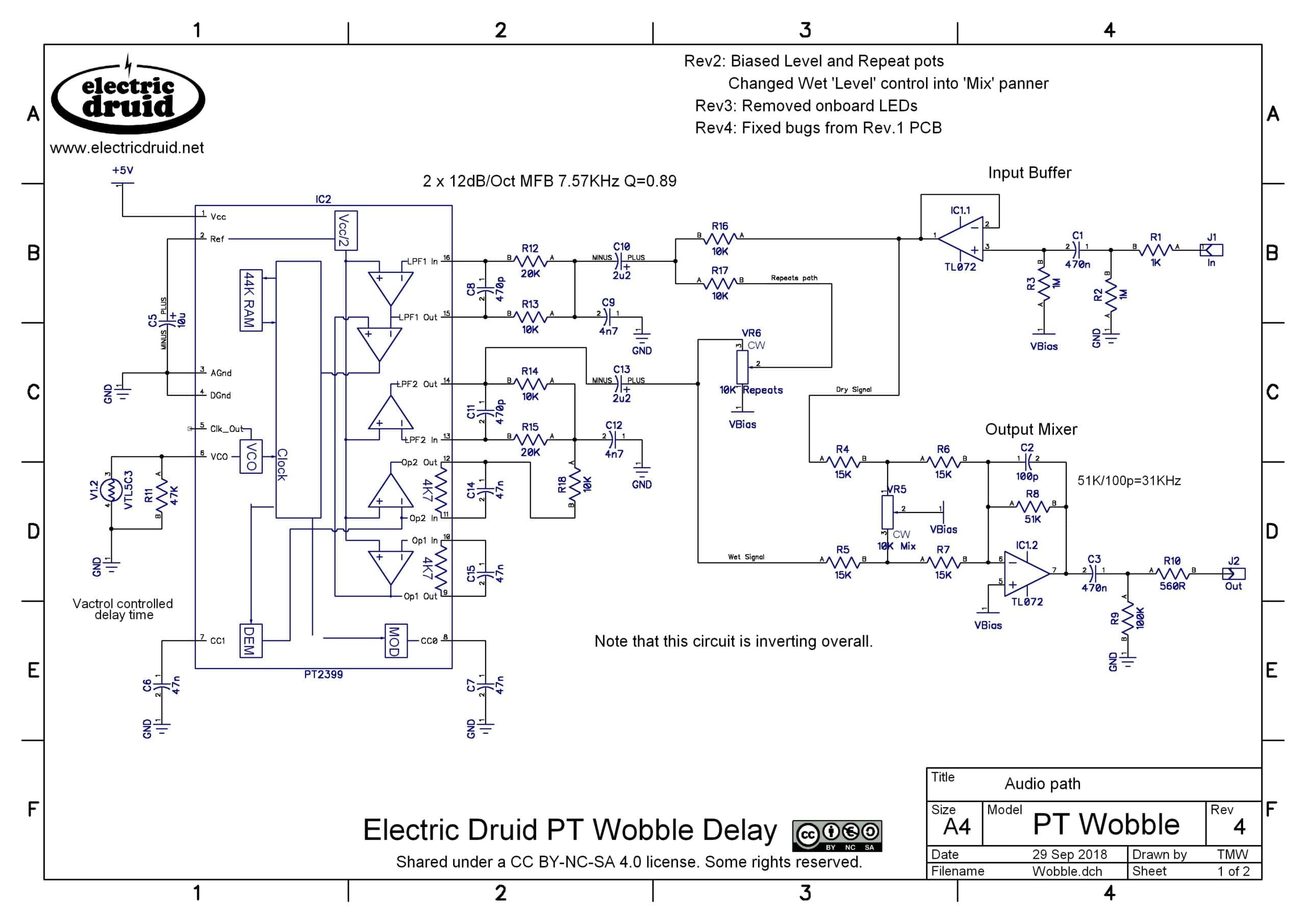
We start in the top-right with a standard op-amp buffer circuit. Pretty much all my pedals start with one of these. We then move onto the input filtering around pins 16 and 15 of the PT2399, which I’ve modified from the PT2399 datasheet example. It’s still a Multiple Feedback (MFB) filter, but I changed the values using this tool. Once the signal has been through the filter, it stays inside the PT2399 and goes to the delay. After that, we come to the post-delay filtering around pins 13 and 14, and finally back to the outside world at C13. From there, the signal splits, with one path going to the Repeats pot and back to the input filter via R17, while the other path goes to the Wet/Dry output mixer, IC1.2. This is a useful building block circuit since it can be used to crossfade between any two signals using a single pot. I learned about it originally from R.G.Keen’s Panning for Fun article.
The usual 50K “Delay Time” pot on pin 6 of the PT2399 is replaced with a vactrol and a 47K resistor. As we discussed in the Mini Tremolo article, adding a resistor in parallel with the LDR of a vactrol like this allows us to set the maximum effective resistance of the LDR. In this case, we’re limiting it to 47K, because that’s about as long a delay as you can get out of the PT2399 before it becomes totally crunchy. By all means experiment with larger values for R11 if you wish. It’ll get crazy lo-fi.
That’s the audio path, and aside from adding an input buffer and a proper wet/dry mixer, it’s a pretty typical PT2399 circuit. The wild stuff happens when we apply modulation! So let’s look at the StompLFO part of the circuit:
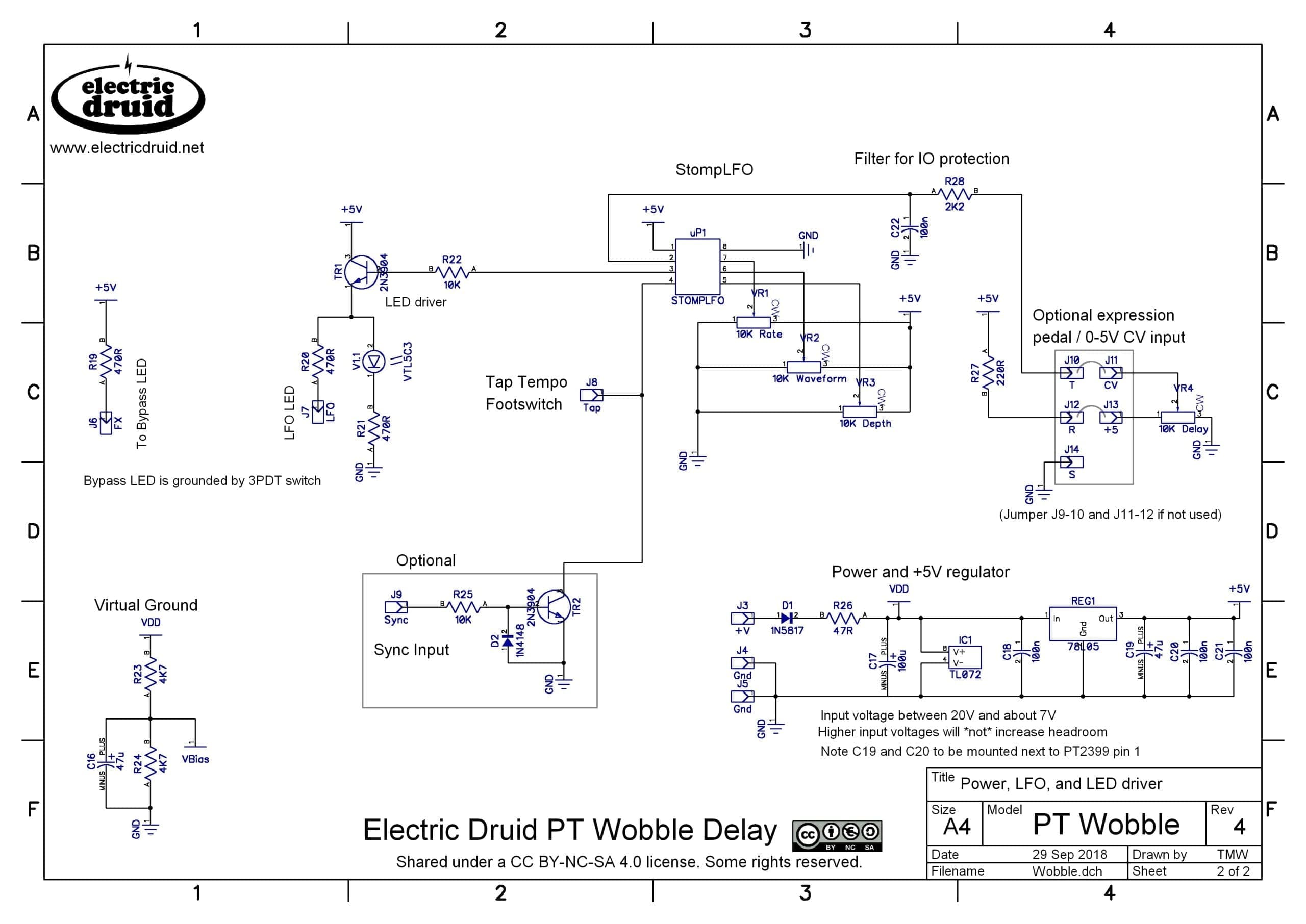
Again, like the Mini Tremolo, we have stompbox-standard power input protection and filtering, and the virtual ground creating a Vbias level, which is essential for single supply op-amp circuits.
For the StompLFO itself, I’ve drawn it much more tricked out than the Mini Tremolo version, but you can mix and match between the two circuits and either simplify this one or add these tricks to the other.
So what’s going on? Well, we’ve got a 10K Delay pot top-right that is connected to a TRS jack socket. This allows you to plug in an expression pedal to replace the delay pot, so you can tweak the delay time with you foot for wild pitch-bending effects. I borrowed this from the FilterFX pedal, where the expression pedal allows you to use the filter like a wah. Since the StompLFO is only concerned with the voltage at pin 2, what value of pot the expression pedal has in it shouldn’t matter too much. Anything from 10K to 100K will be fine, and other things outside that range might work too, but I haven’t tried it. If you don’t want the expression input, just wire the delay pot between 5V and Gnd like the other three and take the wiper direct to pin 2. You don’t need the socket, R27, R28, or C22.
I’ve also shown a connection for a Tap Tempo footswitch J8/Tap. This should be a momentary SPST switch, and the other connection goes to a ground connection somewhere. Note that this is not a tap tempo delay! It’s setting the rate of the LFO, not the delay time. I’ve also shown an optional Sync Input, which would allow you to synchronise the LFO to incoming clock pulses from another bit of gear – a drum machine or sequencer or something.
I haven’t shown the 3PDT wiring on this schematic, but all the connections you need are shown, including power for the Bypass LED and an LFO LED to indicate the rate.
Going further
One thing that might be interesting to experiment with would be adding a second PT2399 for longer delay times (and/or better quality!). You could add another vactrol controlled by TR1 just like the existing one, it won’t blow up the StompLFO. The fact that there’s a drive transistor in this circuit means we’ve got loads of potential current if we need it.
Since both this circuit and the Mini Tremolo use vactrols to control the modulation, any LFO that can drive a vactrol’s LED can be used in place of the StompLFO. That means the TAPLFO3 or VCLFO10 could be used instead, for even more features. Those chips have PWM outputs and don’t need filtering to drive a vactrol, just like the StompLFOs PDM output.
If you build this, let us know what you think of it and how you got on in the comments below. Thanks!
mini tremolo + PT wobble delay in one enclosure = wobbly P tremolay!
I have a question: where does the STOMP LFO part of the circuit connect with the Delay part of the circuit? I am a little confused how they affect each other here.
The trick is the vactrol! The “V1.1” LED and the “V1.2” LDR are parts of the same device, a VTL5C3. When the LED lights, it lights up the LDR and the resistance drops. And when the LED goes out, the LDR is in the dark, so the resistance goes sky high. There’s no direct *electrical* connection between the two sections – instead, it’s done *optically*.
Hi Tom,
So I “successfully” built this pedal. It works and is pretty trippy at times. Very much like a glitchy tape machine, which I love. However, I have a few questions, or concerns to check in with you about.
1. There is supposed to be 8 wave forms, but some are either too subtle, or perhaps I am not hearing them. As of now, I can only discern about 5. Would converting the wave pot to a rotary switch help?
2. I also noted that some waveforms are very extreme, particularly the square and sawtooth waves. Instead of a gentle ramp up and down, they seem to just go from one extreme to the other, and not in a good way. I have found some sweet spots by dialing in the other pots, but is there any way to reduce the number of waveforms to maybe 4 of the better ones?
3. The output volume seems very low. I added an overdrive before this pedal and it blew it away, even with the OD being barely turned up. Any thoughts on improving the output gain?
4. In one article, you mentioned possibly using the TAPLFO chip in this circuit. Do you have any advice on how to do that?
That’s about it. Great circuit. I still have some tweaking to do, but it will be one I will be messing with for a while. Thank you!
Hi Jeremy,
Glad you’re up and running at least. Let’s go through your questions one by one:
1) Converting to a rotary switch makes the switches much more obvious since it adds mechanical feedback, instead of relying purely on your ears. Of all the changes, the triangle-to-sine is probably the hardest to hear. Personally, I don’t find the others that difficult to detect, but that’s probably practice as much as anything.
2) Some of the waveforms *do* sound more extreme than others. That much is true. But the ramps definitely ramp up and down and don’t jump from one extreme to the other. If that’s happening, something weird might be going on. What vactrol did you use? How is the LED current limiting resistor set up?
2b) Yes, if you were to add a rotary switch, you could choose a 4 position switch and then choose which voltages from the resitor chain to connect to it. You don’t have to have all the waveforms, and you could even change the order if you wanted.
3) This doesn’t sound entirely right either. There should be no volume drop in the circuit. If anything, it adds volume since the delayed signal is added in. You can increase the output gain by increasing the value of R8, but you shouldn’t really need to. If you increase it a lot, you’ll need to reduce C2 a bit too to avoid losing high end.
4) You could take the “Single Supply Tap Tempo LFO” circuit from page 13 of the datasheet and then leave off the Sallen-Key filter. The remaining block drops straight into the Mod Delay circuit, with the TapLFO’s PWM output replacing the StompLFO’s PDM output.
Hope that helps. Good luck!
I built this circuit but I’m not sure if the cross fade panner is working as it is supposed to. My expectation is that we’d get fully clean when the pot is turned one way and fully wet when turned the other. What I’m getting is delayed signal on one side, clean in the middle, and delay w/ feedback at the other extreme. Is this expected behavior or me just having a mistake in my breadboarding of the circuit?
There are also two other items that I’ve been working on:
1. a noise filter to cut some of the underlying noise from the pt2399 chip on the output
2. preventing run-away volume swell when the pt2399 goes into self-oscillation with the repeats
For 1/ I was thinking a tunable high-pass filter on the output of the repeats output pin and for 2/ I was again wondering if there was maybe a compressor type circuit I could use to normalize the volume out
Do you have any ideas on that?
Hi Lane,
It definitely sounds like somethings wrong with the wet/dry panner. It should act as you expected, all dry at one end, all wet at the other, and a mix in-between. It sounds like something is mixed up somewhere.
Adding a tunable highpass filter is a nice idea. I had a highpass filter in the Digidelay project and it gives a nice tone to the repeats – makes them sound “lighter” and like they’re floating away.
For the oscillation, some people add clipping diodes in the feedback path – that limits the maximum level and helps keep the volume under control. I haven’t tried it, so I can’t offer much advice on that, sorry.