
Last time we looked at reconfigurable filters, filters that include switches to rearrange parts of the circuit during normal use. However, that’s not the only way to produce different responses from a single filter circuit. This time, we’ll look at another approach: pole mixing.
“Pole mixing”? It sounds like stirring a cake with a broom handle…
Either that or a DJ doing a set up a flagstaff, right? Nope!
You’ll have heard people talking about filter “poles”. Without going into the maths of it, this is related to the number of 6dB/oct stages they have. A 1-pole filter has one stage, a 2-pole filter has two stages, etc etc. Most classic synth filters are 4-pole filters, although 2-pole filters have had their proponents, notably Oberheim.
Let’s say we’ve built a four-pole lowpass synth filter, fat and juicy and with enough funk to make your punks daft. It could be based on OTAs, or VCAs, or it could be a transistor ladder filter. Usually you’d take the output of the filter from the output of that final fourth stage. But that’s not the only option. You don’t have to. You could instead take the output from the first, second or third stage. If you did, you’d get a 1-pole, a 2-pole, and a 3-pole response to choose from. You could even take the output straight from the input, and thereby provide a way to bypass the filter.
Pole-mixing is based on the fact that we have all of these different responses available from the filter core. By mixing them in different amounts, both positive and negative, we can create many different responses.
Wow! So how does that work?
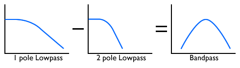
To give a simple example, we can imagine making a highpass filter by starting with the input signal and then taking away a lowpass filtered version of that signal. What’s left is the bit that the lowpass filter removed – the high frequencies.

This is a simplification, but it explains the idea. In a similar way, by taking a lowpass response and removing another, we can make a bandpass response.
More complex responses need more complicated mixing, and a careful balance of the various outputs, but the principle is the same.
Oberheim Matrix/Xpander pole-mixing filter
The first commercial synth I ever saw with a pole-mixing filter was the Oberheim Matrix-12 / Xpander. I can’t find out accurately which of these synths hit the market first, but they’re basically different versions of the same thing, so it doesn’t matter much. The filter was a revelation to the analog synth world of the mid 1980s. Never before had an analog polysynth had a filter that could produce 15 different filter responses. There have been very few since that do.
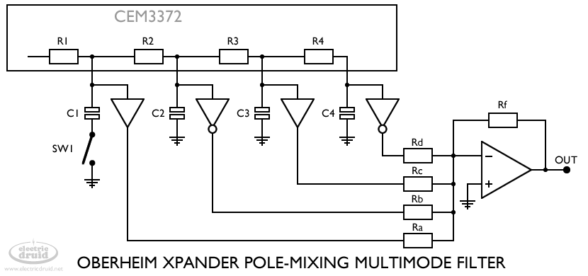
The Matrix/Xpander uses the filter in the CEM3372 synth voicing chip, and cleverly hacks the chip, tapping the signals from each stage’s filter capacitor with a buffer to get outputs from each pole. Note that the buffers alternate between non-inverting and inverting. This is because we need to be able to subtract poles from the mixture as well as add them.
Another important point is that the Xpander filter doesn’t directly use the input signal. Instead, in cases where the input signal is required the filter capacitor for stage one is disconnected (SW1) which gives us the input signal followed by three lowpass stages.
What a great idea! Does anyone build a synth with a pole-mixing filter these days?
The same idea appeared in the Mutable Instruments Shruthi 4-pole Mission filter board back in 2015. It has a filter core based on the V2164. It uses the same tactic as the original Xpander, using a an eight-way switch to select resistor combinations, coupled with a switch to disable the first filter stage. Mutable Instruments don’t build Shruthi’s any more, but the design files are available if you want to have a go.
The Intellijel Polaris Eurorack module is also based on the V2164, but includes more resistor combinations for a total of 27 different responses.
At the other end of the synth market, the same idea appeared again more recently in the Modal Electronics 008 synth. Similarly, this uses eight selectable resistor sets and a switchable first stage – it is possible to deduce this from the selection of responses that it offers. Oberheim’s idea from 1984 has survived into top end synths in 2017!
What responses can we get from a pole-mixing filter?
The usual way to describe the responses in a filter like this is to describe the weightings of the different outputs. The input is first, followed by the 1-pole output, then the 2-pole, 3-pole, and finally the 4-pole. These are sometimes labelled A, B, C, D, and E.
I’m presenting it like this:
- Response name {Input, 1-pole, 2-pole, 3-pole, 4-pole}
Note that because the stages are inverting, the 1-pole (6dB/oct) and 3-pole (18dB/oct) outputs are inverted with respect to the input. It is important for the mixing that the inputs to the mixer alternate between non-inverted and inverted (e.g. we add one pole, then subtract the next, add the next, and so on). Since this is achieved by using inverting stages, or adding inverting buffers to some stages (as in the Xpander design), these inversions are ignored in the weightings below. It boils down to “the second and fourth columns are inverted”.
Lowpass responses
These are the simplest, since we can just take the output from each filter stage, and no mixing is required.
- 6dB lowpass {0, 1, 0, 0, 0}
- 12dB lowpass {0, 0, 1, 0, 0}
- 18dB lowpass {0, 0, 0, 1, 0}
- 24dB lowpass {0, 0, 0, 0, 1}
Highpass responses
These are proper mixed responses that need careful matching of the outputs. If the outputs are not well matched, the cancellation of the signal in the stop band will not be good, and you’ll have a highpass filter with some “leakage” of low frequencies. For musical use, this may well not be that important.
- 6dB highpass {1, 1, 0, 0, 0}
- 12dB highpass {1, 2, 1, 0, 0}
- 18dB highpass {1, 3, 3, 1, 0}
- 24dB highpass {1, 4, 6, 4, 1}
Bandpass responses
Note that a 12dB bandpass filter can be formed by a 6dB highpass followed by a 6dB lowpass. Thus the coefficients are the same as the 6dB highpass, but “pushed right” by one place, giving an extra 6dB lowpass. The same principle applies for the 24dB bandpass. The coefficients are the same as the 12dB highpass, but pushed right by two places, giving an extra 12dB lowpass.
- 12dB bandpass {0, 1, 1, 0, 0}
- 24dB bandpass {0, 0, 1, 2, 1}
It’s also possible to have asymmetric bandpass responses, with unequal slopes on the two sides.
- 6dB highpass + 6dB lowpass = 12dB bandpass
- 6dB highpass + 12dB lowpass {0, 0, 1, 1, 0}
- 6dB highpass + 18dB lowpass {0, 0, 0, 1, 1}
- 12dB highpass + 6dB lowpass {0, 1, 2, 1, 0}
- 12dB highpass + 12dB lowpass = 24dB bandpass
- 18dB highpass + 6dB lowpass {0, 1, 3, 3, 1}
Notch responses
A 12dB notch filter is formed by adding the 12dB lowpass response to a 12dB highpass.
- 12dB notch {1, 2, 2, 0, 0}
Presumably you could do the same thing with a 18dB highpass and 18dB Lowpass, but I haven’t confirmed it:
- 18dB notch {1, 3, 3, 2, 0}
There are many other possible notch responses. For example, you can create a notch by mixing an allpass response with the input signal (the classic phaser).
Allpass responses
It is also possible to get allpass responses from the filter core.
- 6dB all pass {1, 2, 0, 0, 0}
- 12dB all pass {1, 4, 4, 0, 0}
- 18dB all pass {1, 6, 12, 8, 0}
- 24dB all pass {1, 8, 24, 32, 16}
Since an allpass filter doesn’t actually remove anything, these responses are underwhelming on their own. However, adding the allpass output to the input causes phase cancellation and creates notches that we can hear. This changes these responses into a phaser.
These responses have all had {1,0,0,0,0} added and then been simplified by dividing by two.
- 6dB phaser {1, 1, 0, 0, 0}
- 12dB phaser {1, 2, 2, 0, 0}
- 18dB phaser {1, 3, 6, 4, 0}
- 24dB phaser {1, 4, 12, 16, 8}
Ok, so what filter responses did the Oberheim Xpander/Matrix12 include?
It included eight basic responses, which could then be altered by disconnecting the first stage. This effectively moves the coefficients left one place. The responses from the Xpander service manual are:
With the first stage switched on
- 24dB lowpass {0, 0, 0, 0, 1}
- 12dB lowpass {0, 0, 1, 0, 0}
- 12dB highpass + 6db lowpass {0, 1, 2, 1, 0}
- 18dB highpass + 6db lowpass {0, 1, 3, 3, 1}
- 24dB bandpass {0, 0, 1, 2, 1}
- 12dB notch + 6db lowpass {0, 1, 2, 2, 0}
- 12dB bandpass {0, 1, 1, 0, 0}
- 18dB allpass + 6dB lowpass {0, 1, 3, 6, 4}
With the first stage switched off
- 18dB lowpass {0, 0, 0, 1, 0}
- 6dB lowpass {0, 1, 0, 0, 0}
- 12dB highpass {1, 2, 1, 0, 0}
- 18dB highpass {1, 3, 3, 1, 0}
- 12dB highpass + 6dB lowpass {0, 1, 2, 1, 0}
- 12dB notch {1, 2, 2, 0, 0}
- 6dB highpass {1, 1, 0, 0, 0}
- 18dB allpass {1, 3, 6, 4, 0}
Note that the fifth response with the first stage switched off is a copy of the third response with it switched on (12dB HP + 6dB LP). This is why the Xpander/Matrix12 had 15 responses instead of the 16 you’d expect – one is a duplicate.
Building a pole-mixing filter
There are two parts to a pole-mixing filter, the 4-pole filter core itself, and then the pole mixing. Since we need alternate positive and negative outputs, it helps if the filter stages are inverting. Luckily for us, this is easy to arrange with either the V2164 or the AS3320. The two filters are below. Both of them share the same mixing section.
Problem! There’s a mistake in these schematics!
There’s a bug in these schematics. It doesn’t affect everything, but it’s pretty serious. The problem is that the “input” tap needs to include any signal fed back for resonance. Without this, any responses that include resonance and the input tap won’t respond correctly. This affects highpass filters, notches, and allpass. Lowpass and bandpass responses are ok, and anything where resonance isn’t used is ok.
With the 2164 design below, this could be fixed by taking the resonance VCA output back to the input buffer instead (although it’ll need an inversion to account for the inverting mixer, so we’d have to flip the inputs on the resonance OTA VCA). On the 3320 design, it’s more difficult because the resonance VCA is internal so we can’t get at it easily.
Note that this problem doesn’t affect designs like the Xpander or the Shruthi 4-pole mission because they don’t use the “input” exactly. Instead, they turn off the filtering action of the 1st stage and use that as the input for responses that require it. This approach would be possible here too.
V2164/AS2164 4-pole voltage-controlled filter core
The best way to set the V2164/AS2164 as a filter is to use the VCA to control the cutoff frequency of an op-amp integrator. Since these integrators are inverting, our filter stage is inverting.
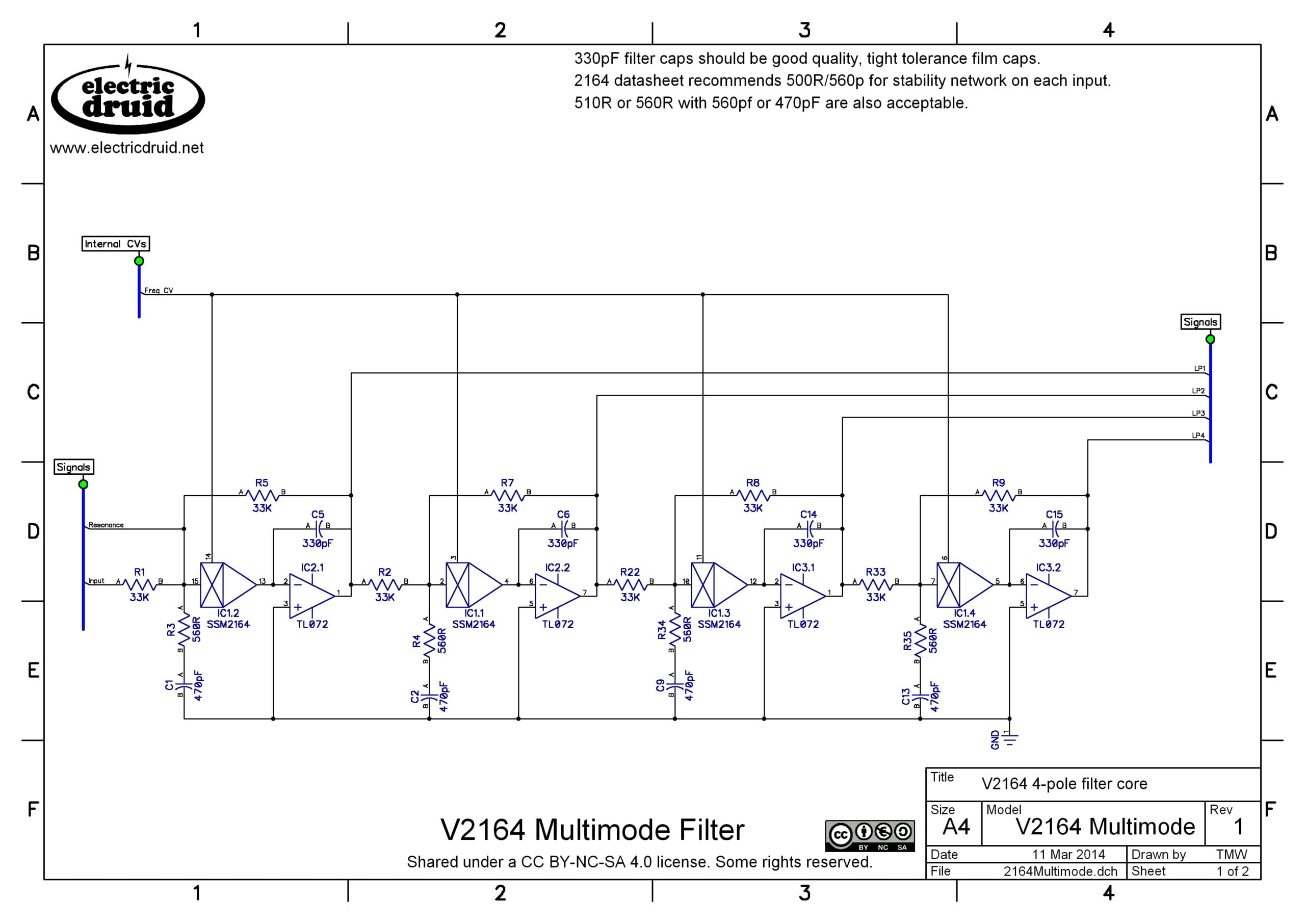
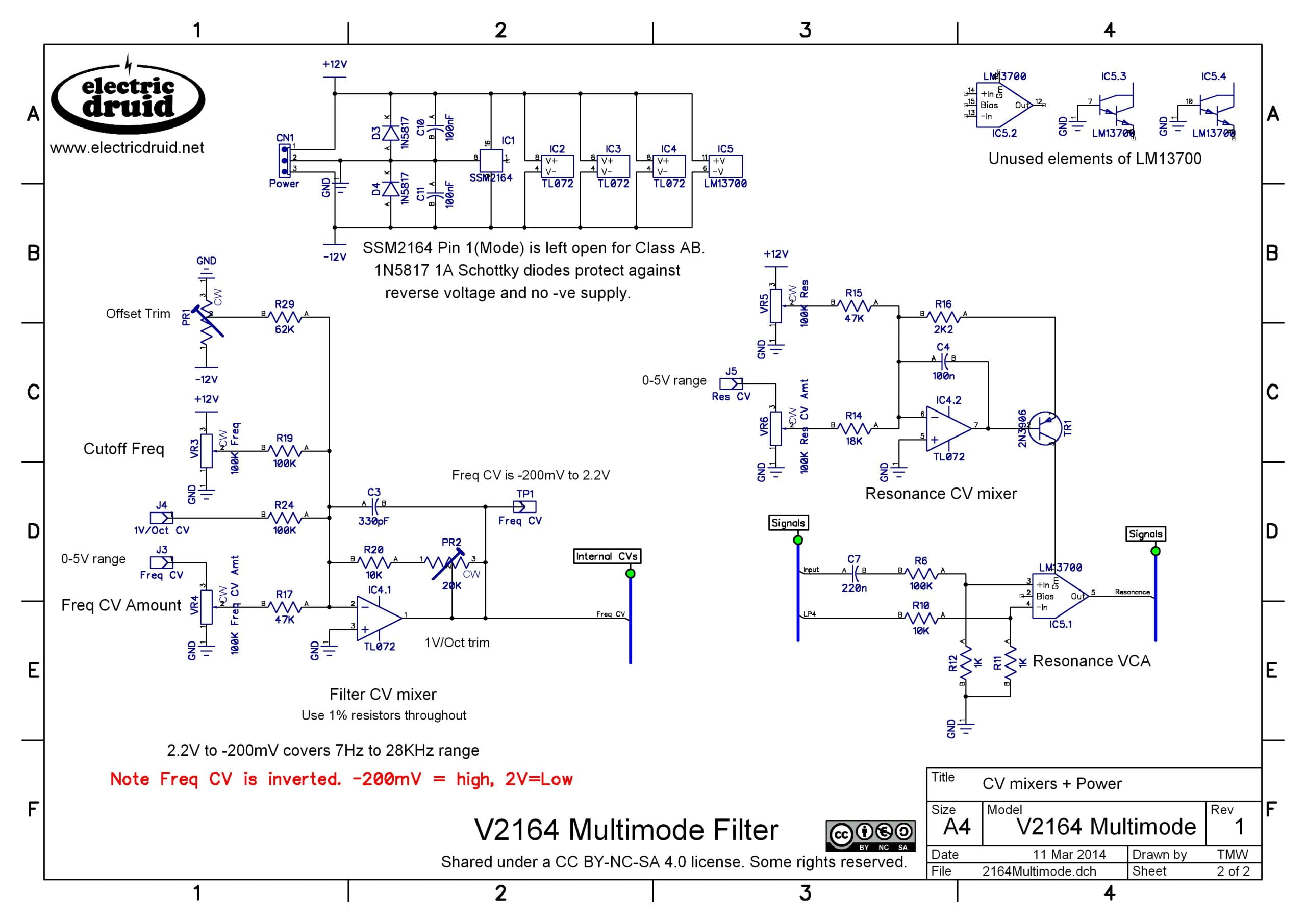
This design is based on Mutable Instrument’s Shruthi 4-pole Mission filter mentioned above. The resonance CV mixer has been altered to allow external CV inputs and add some further protection.
AS3320 4-pole voltage-controlled filter core
We can simplify the circuit even further by using the AS3320, which doesn’t need external buffers, and includes voltage-controlled resonance. Furthermore, the stages inside the chip are inverting, so we don’t need to add anything. This makes a fantastically simple filter core for a very powerful filter.
About the only downside of the chip for this use is the fact that the filter stages have a heavy DC bias (6.5V) this makes large DC-blocking caps necessary on the stage outputs. It’d be nice if these weren’t required. Still, it’s not a big thing.
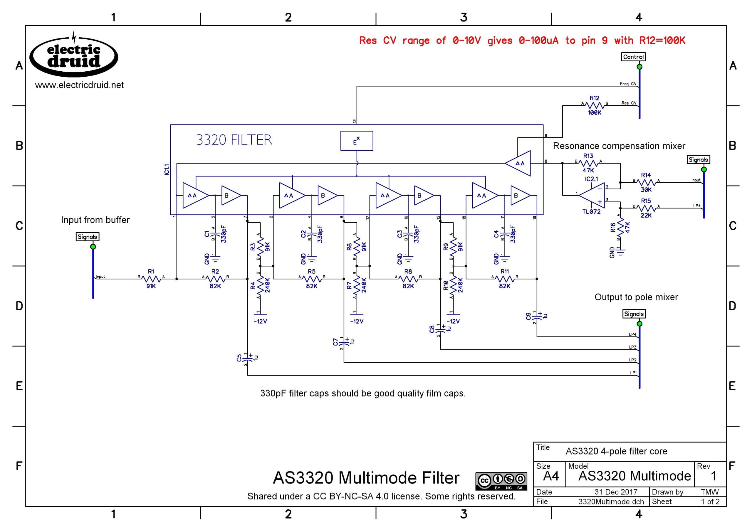
Pole mixer for either V2164/AS2164 or AS3320 filter core
This mixer takes the five outputs (Input, LP1, LP2, LP3, LP4) marked on the above schematics and provides many different responses.

The pole mixer is a standard inverting op-amp audio mixer circuit. The only complicated part of a pole mixer circuit like this is choosing the resistor values so that it is possible to get other values that give the required gains. The gains need to be accurate, so 1% resistors or better must be used. If you choose E24 series values, you will probably need to combine values to get accurate results, so many pole-mixing designs use E48 or E96 values for at least some cases.
All of the basic lowpass, highness, bandpass, notch, and all pass responses listed above can be done with only five coefficient (gain) values: 1, 2, 3, 4, and 6. A good design should make these values easy to find. The only value in the E24 series that comes close is 30K, which gives 15K for x2, 10K for x3, 7.5K for x4 and 5K for x6. All of these except 5K are standard E24 values. For 5K, the closest is 4.99K from the E96 series. More complex responses including some notches and higher-order all pass filters require more exact values which will be beyond the E24 series whatever you do.
The Xpander and Shruthi designs use a 100K resistor as the basic value. This means we need 50K to give a gain of two, 33.3K to give gain of three, 25K to give a gain of four, and 16.667 to give a gain of six. None of these values are exactly possible, with 49.9K, 33.2K, 24.9K, and 16.5K being the closest values available, all from the E48 or E96 series.
There is an alternative approach, if board space is less of an issue. If we choose a 100K resistor as our basic value, paralleling two 100K resistors gives us a 50K value, and paralleling three gives us 33.3K. We can carry on adding more to get other multiplication factors. So far, I’ve never seen a circuit which took this approach, but it should work and might make sense with resistor arrays.
Note that it is possible to use an analog switch IC to select between different resistor sets as demonstrated in the schematic above, but it is also possible to use multiple mixers to provide various outputs simultaneously.
Multimode filters, Part 1: Reconfigurable filters
Multimode filters, Part 3: State variable filters coming one year soon!
Update: the first pole-mixing filter
I’d previously thought that the Oberheim Matrix/Xpander filter discussed above was the earliest commercial pole-mixing filter, but Steve Ridley recently brought the Siel Mono synth to my attention (Thanks Steve!). This synth came out in 1979/1980, so it predates the Oberheim by several years. It uses LM13600 dual OTAs for the filter core, and uses pole-mixing to provide highpass and bandpass outputs as well as the typical lowpass.
Bernie Hutchin’s Electronotes discussed the concept in the January 1978 issue, so the idea was clearly in circulation in the late-70s/early-80s.
Pole-mixing simulation
David Moylan has done a great simulation over on the Expedition Electronics webpage where you can play around with the coefficient values and see the resulting filter responses in realtime. Really handy!
Expedition Electronics polemixing simulation
Further reading on pole-mixing filters
The Xpander service manual is where I first saw this technique described.
“Multifunction VCF” from Oberheim Xpander service manual
However, Oberheim weren’t the first. They probably read about it in Bernie Hutchins’ Electronotes newsletter!:
EN85 “Additional Design ideas for Voltage Controlled Filters”, Bernie Hutchins
Here’s the earliest-known commercial application of pole-mixing, in the Siel Mono. It’s also not a bad design if you want a nice vintage 4-pole OTA filter. It could be built with the LM13700 with no problems:
Sound Semiconductor have also recently released an extremely good application note which covers many filter-building techniques, including this one. One interesting twist they give it is to use pole-mixed bandpass responses for the feedback to avoid the “passband droop” effect at high resonance – a nice trick!
“AN701 – Designing VCFs”, Sound Semiconductor
There’s also an excellent explanation over on the Mutable Instruments site:
“SSM2164 4-pole with pole mixing”, Mutable Instruments
Comments and Feedback
As usual, if you spot any errors, get in touch, or comment below.
So that’s how they do it…
An interesting and informative article (as ever).
How easy would it be to do this in a DSP? This would mean that you wouldn’t have to worry about component tolerances and drift and could extend it to higher order configurations with no hardware overhead. Moreover you could get the chip count down to 1.
How easy would it be in a DSP?! Very easy indeed!!
The Powerwave synth (paper presented at DAFX-05) is one example: https://www.researchgate.net/publication/241280072_POWERWAVE_-A_HIGH_PERFORMANCE_SINGLE_CHIP_INTERPOLATING_WAVETABLE_SYNTHESIZER
You’re exactly right about the reasons why – digital accuracy means you get much tighter results for responses like the highpasses and complex mixtures. In many ways, it’s a no brainer for digital!
I wrote multimode filter recently in C++, Arduino framework on STM32F411RE. I did it without I2S, using DAC8551 instead with SPI. I configured it to fire in around 20kHz, first performing calculations and then writing value to DAC. Unfortunatelly I can’t go faster than around 28kHz, and with sophisticated response I had to go even below 20kHz to keep ADC input from pot readable. Despite this fact I’m able to filter wave generated by simply overflowing variable.
I wish I could have a very fast microcontroller with very fast spi, cause I don’t like the whole STM32CUBE environment. I know that it’s giving a much much more possibilities, but I don’t have to much time to learn new things – I’m utilizing ones I know already 🙂
Because I probably will not use this code commercially, here you have it. Below there I’m performing just performance measurements, but you can rewrite it to run it in certain time intervals and write output to DAC. Enjoy it, optimize it and use it in your own projects 🙂
#include
double audioin[1000];
double audioout[1000];
#pragma region MultimodeFilter class
class MultimodeFilter{
public:
void setFrequency(double f);
void setResonance(double q);
void setResoCompensation(double c);
void setPoleMixing(byte passthru, byte poleone, byte poletwo, byte polethree, byte polefour);
double process(double input);
private:
double K = 0;
double L = 0;
double reso = 0;
double resocomp = 1;
double intermedsample1 = 0; //wyjścia stopni
double intermedsample2 = 0;
double intermedsample3 = 0;
double intermedsample4 = 0;
double pintermedsample1 = 0; //poprzednie wyjścia stopni
double pintermedsample2 = 0;
double pintermedsample3 = 0;
double pintermedsample4 = 0;
byte stagemix0 = 0; //zmienne miksujące odpowiedź filtra
byte stagemix1 = 0;
byte stagemix2 = 0;
byte stagemix3 = 0;
byte stagemix4 = 1;
};
void MultimodeFilter::setFrequency(double f){
K = f;
L = 1 – K;
}
void MultimodeFilter::setResonance(double q){
reso = q;
}
void MultimodeFilter::setResoCompensation(double c){
resocomp = c;
}
void MultimodeFilter::setPoleMixing(byte passthru, byte poleone, byte poletwo, byte polethree, byte polefour){
stagemix0 = passthru;
stagemix1 = poleone;
stagemix2 = poletwo;
stagemix3 = polethree;
stagemix4 = polefour;
}
double MultimodeFilter::process(double input){
intermedsample1 = pintermedsample1 * L + K * input +
constrain((pintermedsample4 * reso * -1), -5000, 5000) + //resonance feedback – constrain ogranicza rezonans
(input*(reso*-1*resocomp)); //kompensacja rezonansu
intermedsample2 = pintermedsample2 * L + K * intermedsample1; //next three stages
intermedsample3 = pintermedsample3 * L + K * intermedsample2;
intermedsample4 = pintermedsample4 * L + K * intermedsample3;
double output = (input * stagemix0)
+ (intermedsample1 * stagemix1 * -1)
+ (intermedsample2 * stagemix2)
+ (intermedsample3 * stagemix3 * -1)
+ (intermedsample4 * stagemix4);
pintermedsample1 = intermedsample1;
pintermedsample2 = intermedsample2;
pintermedsample3 = intermedsample3;
pintermedsample4 = intermedsample4;
return output;
}
#pragma endregion
MultimodeFilter VCF;
void setup() {
Serial.begin(115200);
int16_t val = 0;
for (int i = 0; i < 1000; i++){
audioin[i] = val;
val+=400;
}
VCF.setFrequency(0.2);
VCF.setResonance(0);
VCF.setResoCompensation(1);
VCF.setPoleMixing(0, 0, 0, 0, 1);
}
void loop() {
unsigned long time = millis();
{
for (int i=0; i<1000; i++) audioout[i] = VCF.process(audioin[i]);
}
time = millis() – time;
int16_t val = 0;
for (int i=0; i<2500; i++){
Serial.println(VCF.process(val), 0);
VCF.setFrequency(0.0 + i / 12000.0);
val += 200;
}
Serial.println();
Serial.print("Jedna iteracja (ms): ");
Serial.println(time / 1000.0, 5);
for(;;);
}
Thanks for sharing that, Krzysztof!
No problem! Basic principle of operation I took from book “Musical Applications of Microprocessors”, where author described one pole lowpass filter. It was just a matter of cascading them and summing outputs. I tested it in Excel before writing any code 😀
Still it requires many steps to finish. Resonance is uneven in frequency domain, in upper frequencies it’s not present, in lowest part is too loud. And there also lacks some compensation stuff with sin function, as described in book and how I saw it in Teensy library.
Anyway DSP seems interesting topic, a bit shame that it’s hard to start. And fact that Arduino framework on STM32 doesn’t support i2s and dma, maybe with these features this filter could run at decent 44.1kHz
To speed up this code: use float instead of double, it is sufficient for this kind of filter. Use int_fast8_t instead of byte (the compiler figures out what is best for your platform). Resonance should be clamped from 0..4 (then you don’t need the constrain). stagemix0 to 4 you could keep in float, avoiding expensive conversion from int to float every time you run through the loop.
Thanks for reply 🙂 I got all that bits together already. My knowledge about C++ increades significantly from the time I first wrote this code. So far I did string machine emulator on STM32F407. Six voices, string chorus and phaser. Everything runs on floats specifically, and sounds pretty nice.
There’s the Doepfer A106-6 Xpander filter which uses the CEM3328 to achieve this topology. It gives multiple outs of different responses and is thoroughly investigated by Learning Modular https://www.youtube.com/watch?v=HjfzhI0ZQ50 ; the ‘3328 is a cutdown ‘3372 without the additional vca and mixer inputs iirc.
A thorough, informative article as ever! I did breadboard one of these filters, based on Shruthi and Xpander schematics, and found it had no leakage with regular resistor values. However I did find the resonance to be a lot poorer when the first pole was switched off. The genuine Xpander seems to be the same, judging from examples I’ve listened to on Youtube. I wonder did you encounter this and find the problem solved by using the signal from the buffered input?
I haven’t built the Xpander filter, so I can’t say for sure. What I can say is that in these designs, the resonance feedback remains around four full stages of the filter whatever taps are selected, so there should be no change. In the Xpander design, the usual 4-pole feedback degenerates to 3-pole feedback when that first stage is disabled, so it’s no surprise if it alters the sound.
Hi Tom!
What does the “Resonance Compensation Mixer” do? It’s on the right side of the first schematic for the 3320 filter.
It compensates for the drop in passband volume you typically get with increasing resonance. It does that by feeding some of the input signal into the resonance VCA, so that as the resonance is increased, so is the input signal.
Incidentally, the ‘2164 based filter does the same thing – look at the way both the LP4 and the Input signals are fed to the resonance VCA.
Hi, I’m working my way through the 3320 design and I’m unsure why the RES control at pin9 needs negative protection. From what i can tell the maximum ratings are +-40 mA on all pins and once the cvs go through the 100k resistor just before the pin wouldnt the voltage end up being in the order of uV and similarly low current?
Similarly the Data sheet say max voltage between Resonance control and ground pins is +2v and -18v, so it seems that if anything, positive protection above 2v would seem more appropriate. Not that i think the control voltage at pin 9 would get anywhere close.
Also in the interest of making sure I’ve understood this propoerly, could you confirm the 4P N resistors at the bottom of the pole mixer should be 30k, 15k, 15k, 15k, 15k and not 33k, 30k, 10k, 4k99, 7k5.
Thanks
Hi David,
The Res control could probably manage without the negative voltage protection since as you say the current will be very small. But we have to add the second op-amp anyway to re-invert the mixed signal, so we might as well add the two diodes and get some extra protection.
The Notch mixer resistors looks to be a copy-paste error from the Allpass case above it – sorry, my mistake. Your 30K, 15K, 15K, 15K, 15K values should be correct. I’ll get an updated schematic uploaded soon.
Thanks for spotting that and bringing to my attention.
I’m halfway through with the 3320 variant on a protoboard from MIAW. I thought about a 8 way rotary switch instead of the electronic switch. All variants eat up lots of space. How about using electronic potentiometers? Problem: I could not find one that takes +/- 12v. Any hints?
I like the digipots idea – easily programmable and good repeatability. For higher voltage devices, Microchip do some, and so do Analog Devices:
https://www.microchip.com/en-us/products/data-converters/digital-potentiometers
https://www.analog.com/en/parametricsearch/10982#/p2840=20|33
I’m sure other manufacturers have similar things. I just happen to know about these ones.
Yes, it eats up space, but that’s partly because the temptation is to include every possible option! In reality, three or four good options are much better than a dozen or more that you hardly ever use, and that can be done with just a few resistors and doesn’t need a huge PCB.
I’ve been experimenting – successfully, within the scope of my very unexacting criteria – with a design that does the mixing via 2164 VCAs.
I’ve often wondered about this, since the multiple-VCAs-on-a-single-chip makes it very appealing. I’ve never tried it though, so good work!
Pretty easy to drive the VCAs from a uP+DAC too, and you’ve got a programmable filter that could morph from one response to another! (there are some commercial modules that do this already, although I don’t know if they use this method).
Why isn’t it possible to just mix the final pole of a LPF with the input signal to get a HP?
Phase shifts, mostly. The lowpassed signal is also variably shifted in phase, so if you subtract it from the input signal, you don’t necessarily cancel the parts you think you’ll cancel.
Thank you for the quick response (and the useful article)!
I figured as much, but for whatever reason I thought each filter pole causes a 90⁰ phase shift so that a 4-pole filter would result in a 360⁰ phase shift. After a cursory investigation I realise that it isn’t that simple and not correct. Probably misunderstood something I’d read sometime ¯\_(ツ)_/¯
Hi Tom,
Thanks for another great article, and for sharing these schematics!
After in-depth review of the CEM3320’s data-sheet (see my comment on the previous article in this series), I believe your AS3320 4-pole filter core schematic may have error (or perhaps better described as an inefficiency?). With VCC = +12V and RC = 91K, I think R2, R5 and R8 (referred to as RF in the CEM3320 data-sheet) should be 100K, not 82K.
Reasoning: with RF = 82K and RC = 91k, the gain of filter stages 2, 3 and 4 will only be 0.8328, instead of unity.
I note that the Elka Synthex filter circuit (as seen in your previous article; one of the few 3320 examples that uses +12V supply) uses 82K for both RF and RC, (maybe) resulting in a gain of 0.9242 (though I believe this may be impacted by the diodes present in that design).
—
FWIW, my research actually started with me wondering why 240K was used for RB (R4, R7, and R10 in your schematic), instead of 220K as seen in the data-sheet examples (which use +15V/-15V supply). My research confirms that with a +12V/-12V supply, when RC = 91K and RF = 100K, then 240K is reasonable value for RB. (IREF = 48.7mA, stage 1 quiescent current = 48.7mA, stage 2-4 quiescent current assuming target VODC = 49.5mA).
Correction: the IREF + quiescent currents listed at the end of my last comment should say ‘uA’ not ‘mA’.
I breadboarded the AS3320 version of your circuit (so far without the pole-mixing) and found it to have real problems… oscillating and nasty artefacts.
Replaced the resonance compensation section with just a 51k resistor and 1uF cap between pins 8 and 10 (as per the AS3320 datasheet) and everything behaved itself.
Reintroduced the resonance compensation section but with a 51k resistor between the op-amp output and pin 8 and all worked as intended.
Thanks Paul. Going back and checking my prototype, there is indeed a 51K between the output of the op-amp and pin 8. Somehow it got left off the schematic. Thanks for finding that for me!
Further playing about with the AS3320 (with uncompensated resonance control) has resulted in the following observations…
As Nathan pointed out, 100k feedback resistors give closer to unity gain for the stages, however the first stage’s gain was still less than unity.
This was found to be due to the resonance control voltage being at 0V (assumed to be zero resonance). The pin actually sits at about -0.56V, so 0V actually applies current. When I biased the resonance control voltage to -0.56V for zero resonance the first stage had the desired unity gain. I should say that these voltages are applied through a 100k resistor, NOT directly.
The resonance compensation is a useful feature. You did it by subtracting an inverted proportion of the input signal from the LP4 output. I wanted to know exactly what proportion I wanted to subtract but with the subtraction network given, any change of gain to the inverted signal also affects the non-inverted one.
An alternative approach is to use the op-amp to simply invert the input signal, and then using suitable resistors combine the inverted input with the LP4 output directly at pin 8 of AS3320 since this appears to be similar to a “virtual earth”. This works as well, and I found that with a unity gain inversion and equal values of summing resistors (75k in my case) the input signal level through the filter was neither attenuated nor amplified with increasing resonance. The behaviour can be chosen to suit requirements.
One thing that might be worth noting: How do you get high pass filtering with a combination of low pass filters (and input)? Answer: Cancellation. For a 1-pole HP, for instance, you subtract a 1-pole LP from the input; but if the mixing resistors aren’t exactly equal (or the LP filter gain isn’t exactly unity) the cancellation won’t be exact and it won’t go to zero at zero frequency. For higher order HP the cancellation is more delicate. If for 4-pole HP you use {1, 4, 6.06, 4, 1} instead of {1, 4, 6, 4, 1}, a 1% error in one coefficient, then you only go down 24 dB at zero frequency instead of ∞ dB. In practical terms, -24 dB may be enough that you don’t care, but if you do, you need mixing resistors matched to better than 1% (6.006 instead of 6 gets you to -44 dB) and accurate unity gain from the filter stages. The latter is why Paul Silber’s second to last comment above is important. For filters that do not go to zero at zero frequency, on the other hand, you’re relying less on cancellation and 1% tolerances are fine.
Yes, this is completely true – accurate matching for these responses is important. Use 0.1% resistors or trimming for best results, or accept the slightly-variable results! The *technique* itself is solid though, and for *digital* use it’s perfect, since the problems with accuracy disappear and these responses can be created extremely well.
For example:
Powerwave Synth
I’m a little confused. You give {1,1,0,0,0} as the coefficients for a 6dB highpass, but then later give the same coefficients for a 6dB phaser. That can’t be right, can it?
As a side note, I think it’s interesting that the coefficients for highpass responses appear to form Pascal’s triangle.
I don’t know, it’s a good question. The 6dB allpass response is {1,2,0,0,0}. Adding the input to that gives {2,2,0,0,0}. And then {1,1,0,0,0} is the same as {2,2,0,0,0} except with the level reduced. So that’s the logic of how I got there – is there an error? I’m not sure, sorry!
OK, I was playing around a bit with the simulation and it seems like there isn’t an error, just a confusing naming convention. A 6dB “phaser” *is* a 6dB highpass. It’s a degenerate case. You don’t get the classic multiple-notch phaser effect at fewer than 4 poles: the 18dB “phaser” is a notch+HP, the 12dB is a basic notch, and at 6dB it’s just a highpass; at 24dB you get a double notch. I suspect, but can’t confirm (I admit I don’t really understand the math), that adding more poles would alternate between adding a highpass response (for odd numbers) and adding notches (for even numbers).
Thanks Garth. That kind of makes intuitive sense, in that you can think of a highpass as “half a notch”, so we add one more notch for each pair of extra poles. Much like bandpass filters, which is the same thing “the other way up”. A 4-pole bandpass is one that has a 12dB slope on each side, a 12dB bandpass has a 6dB slope on each side.
There’s some logic in here somewhere, I know there is! We just have to find it!
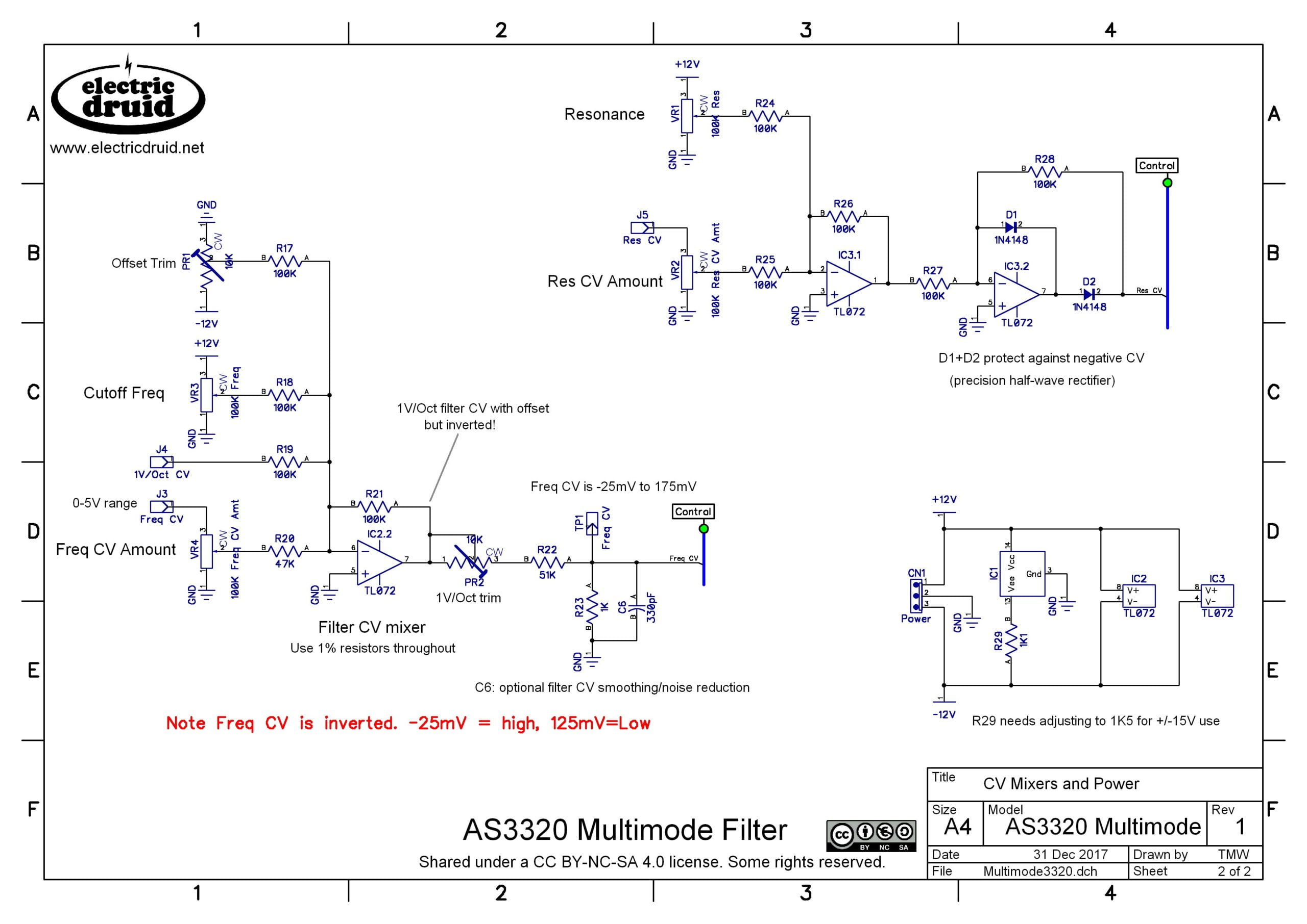
R29 = 1.1k … really? Is that value critical? Because 1.1k isn’t readily available. Of course you could use a 1k and a 100R in series, but will 1k alone or 1.2k not do?
It’s the current-limiting resistor for the internal zener reference, so the value was calculated for 12V. I’d guess 1K or 1K2 would be ok, but I don’t know that for sure. What I’m least sure of is which way to go: A bigger value seems to make sense if it’s for current limiting, but zeners generally regulate better with a bit more current, so that would imply the smaller value. I’m not sure what is best.
Later: Checked some notes, a bit more current would be better to improve the regulation, so go with 1K.
Checking the CEM3320 datasheet, the formula is REE = (VEE-2.7 V) / 0.008 which is (rounding appropriately since the constants have only one or two significant digits) 1.2k. On the breadboard I have 1k+100Ω and I’m not seeing significant CV feedthrough. I haven’t tried varying it yet.
Speaking of feedthrough, the datasheet also says (on the last page) resonance CV feedthrough can be minimized by adding a small DC voltage at pin 8. In your resonance compensation design if there’s a DC offset on the input signal it seems to me that would similarly affect resonance CV feedthrough (up or down), and maybe by a lot if it’s not a small DC offset. I’m probably in way over my head with this, but would it make sense to AC couple the input signal going into the resonance compensation mixer as a way to avoid this? I haven’t experimented with this yet either.
Yes, it is the current limiting resistor for the negative supply zener. I remember trimming it to minimise control voltage feedthrough. A passing reference is made in the AS3320 datasheet but the CEM3320 datasheet gives a fuller explanation.
Thanks Paul!
I was unseccessful doing the 3320 variant on a prototype board (boy, I’ve spent a lot of time on that). Here https://analogoutputblog.wordpress.com/2023/01/22/pole-mixing-on-the-breadboard/ I’ve heard that there are some general problems. Tom, will you fix the schematics one day? Or put a warning message up?!
Hi Martin, thanks for your comment and your detailed write-up. I entirely accept that I’ve had this page up with known errors on it for a long while. It’s a project that I’d like to get back to and do better, but I really haven’t had the time. But putting a note up to inform people of the problems is something I could have done and didn’t (I kept thinking I’d get round to doing a proper re-write any time soon), so you have my apologies for that. I have at least done that now, and I’m sorry that that wasn’t sooner.
Tom
Hello Tom, thanks so much for this gem of an article!
I’m curious if the 4 poles could be mixed by VCAs instead of resistors for continuous morphing between filter modes. Would the in-between coeficients be of musical interest or just complete chaos?
Thanks!
Yes, you could do the mixing with VCAs. Coefficient accuracy would be important, so you’d need accurate control of the VCAs. As to whether the “inbetween” morphs would be interesting, I don’t know. You’d have to experiment changing the coefficients on the Expedition Electronics tool:
https://expeditionelectronics.com/Diy/Polemixing
Thanks!
The Electronotes article was indeed the inspiration for the Xpander/Matrix-12 synths.
Hello everyone, I have installed the pole summing filter with great satisfaction. At the moment, I am managing 4 low-pass filters (6-12-18-24 dB) and 4 high-pass filters with the same slopes. Everything seems to be working, aside from some details, such as the resonance being too prominent. However, I have a problem. The resonance in the low-pass filters works perfectly. In the high-pass filters, though, when I start to activate it, it introduces the portion of the signal that had been filtered back into the signal, and then the resonance begins. For example, if I use a drum sample, without resonance, with the high-pass filter, the bass drum disappears clearly. However, as I begin to activate the resonance, the bass drum completely returns, and it seems as though the filter is being bypassed. Is there a reason for this? Thanks to everyone.
I think you’ve hit the same issue I did. It’s mentioned above in the section “Problem! There’s a mistake in these schematics!”.
The signal you use for the input has to include any signal fed back for resonance. If the resonance is included *after* the input signal is tapped off to the pole-mixer, the responses that include the input (so the high-pass responses, but others too) won’t work correctly. When the resonance is low, the difference is minimal, but as it increases it becomes more and more important.
It’s not hard to fix, but you have to account for it. It seems like it’s something everyone who tries these pole-mixing filters has to deal with – there’s even a note about it on the Expedition Electronics pole-mixing simulation page, and that’s doing it digitally, not in actual circuitry!