
What is a “Multimode filter” anyway? It’s a filter which can provide more than one response. So it might offer a choice of 2-pole or 4-pole lowpass responses, or it might be switchable between lowpass and highpass, or it might have lowpass, bandpass, and highpass outputs.
There are basically three techniques for building multimode filters, which I’d like to look at in the three parts of this series.
How do we build a multimode filter?
The three techniques can be summarised as:
- Reconfigurable filters
- Pole-mixing filters
- State-variable filters (Coming soon)
Let’s start off by looking at Reconfigurable filters, and deal with the other two in the following articles.
Reconfigurable filters
To understand a reconfigurable filter, we need to have a dig through some old data sheets. The data sheets for old CEM and SSM filter chips often included circuits for several types of filter including high pass and lowpass, combining which you can get a bandpass. Although those old chips are mostly hard to get hold of, the techniques are still valid and can be adapted for filters based on OTAs or VCAs.
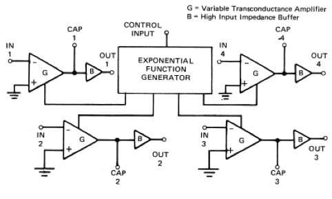
Let’s start with some examples from the CEM3320 datasheet. The CEM3320 is a general purpose chip which can be used as “filter building blocks”. It has four filter stages consisting of an OTA and a buffer, plus an exponential convertor and a resonance VCA. The SSM2040 is a very similar chip, but doesn’t include the resonance VCA. Instead, you have to use an external VCA if you want voltage-controlled resonance. What it does have is a nicer diagram of the guts of the chip:
The classic OTA lowpass filter stage
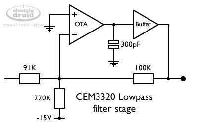
Here’s the CEM3320 datasheet lowpass filter stage:
 The example lowpass filter circuit from the first page of the datasheet is just four of these blocks strung together one after the other.
Ok, so let’s take a look at this filter. There’s an input resistor to the OTA, with a resistor to the negative supply to act as a voltage divider and reduce the input to a level the OTA can cope with. From the OTA, we go to the filter capacitor to ground (this style of OTA filter is often known as “cap to ground”), followed by a buffer, and then a feedback resistor from the output back to the input. In principle it works very similarly to a passive RC lowpass, with the OTA acting as a voltage-controlled resistance. In practice it isn’t quite that simple, since it needs feedback to work correctly, hence the extra 100K feedback resistor.
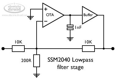
You can do the same thing with the SSM2040, and it looks almost identical. The “electronic music filter” from the datasheet is four of these blocks together (except the first stage has 100K instead of 10K for the input resistor).
The highpass filter
The datasheet also offers a high pass filter stage. So how does the highpass filter differ? Here’s the circuit:
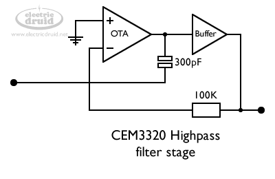 With passive RC filters, we can either have a resistor followed by a capacitor to ground for a lowpass, or a capacitor followed by a resistor to ground for a highpass. We do the same thing here, swapping the positions of the capacitor and the resistor. We feed the signal into the capacitor, and use the OTA as if it were a resistor to ground. The buffer taps the signal from the “top” of the resistor and provides the output.
Again, you can do the same thing with the SSM2040, and it looks almost identical.
How do we turn it into a bandpass?
We’ve established that we can build highpass filters and lowpass filters. How do we turn it into a bandpass?
In this way of thinking, a bandpass filter is just a highpass filter and a lowpass filter in series. If you want a 2-pole bandpass, you need one high pass stage and one lowpass. If you want a 4-pole bandpass, you need two highpass stages and two lowpass stages. The order isn’t strictly important, but since the highpass lets objectionable high frequency noise through, it tends to come first so the lowpass can then remove it. If they were the other way around, any high frequency hiss produced in the lowpass circuit would be allowed to pass by the highpass filter. Consequently, just as a practical matter, bandpass filters tend to be highpass-lowpass rather than the reverse.
Is there anything else the CEM3320 could do?
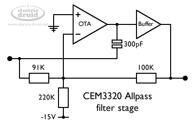
Well, yeah, actually there is. We could make an allpass filter too. That’s a filter which lets everything through, but shifts the signal’s phase as it does so. Consequently allpass filters are very useful for building (wait for it!) phase shifters. Phase shifters produce a notch in the frequency response by mixing this phase-shifted signal with the input, so technically they’re a type of notch filter.
If we look at the circuit for this allpass stage, we can see it’s a mixture of the lowpass and the highpass stages. In fact, it’s like both of them at the same time.
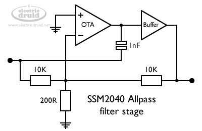
The SSM2040 can also be set up as an all pass filter, and it looks just the same as the CEM3320 version.
Some reconfigurable filter examples
How did people actually use this? There are a few examples from synth history, but the most impressive (if overwhelming) is Craig Anderton’s “Multiple Identity Filter” magazine project, which allows you to configure each filter stage as either highpass, lowpass, or allpass. Not only that, but you have two options for the filter capacitor for each stage so you can alter the roll-off point for different parts of the filter. If that wasn’t enough, you can also arrange the stages either in series or in parallel or some combination of both. It’s fantastically versatile and fantastically difficult to guess what it’ll sound like or do with a given combination. It’s a filter builder’s experimental playground, in short.
Before we look at that, let’s have a look at some (slightly) simpler examples.
Oberheim OB-8
The Oberheim OB-8 is basically a reworking of the earlier OB-Xa. Rather than add a lot of new features, what they did was to concentrate on improving reliability and tuning. They did that by reducing the amount of hardware required and moving many calibration functions into software. Without so many trimmers to keep spot-on, there was a much better chance of the instrument playing in tune. And with less parts inside (LFOs had gone digital, for example) there was less chance of it breaking down.
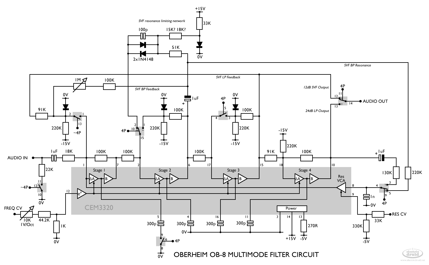
One example of this new philosophy was the filter. Whereas the OB-Xa used two separate filters both based on the CEM3320 to produce a 24dB/Oct and a 12dB/Oct response, the OB-8 uses one CEM3320 filter and allows it to be reconfigured to provide the two responses.
This would be pretty simple, except that the two filters have completely different topologies. One is a simple lowpass 4-pole cascade like the datasheet design, but the other is a 2-pole state variable filter, which is a completely different beast. Consequently, changing the circuit requires 4 x SPST and 3 x SPDT switches, a 4016 and a 4053 CMOS analog switch chip. This means the filter uses one chip for the filter core, and two more chips for the reconfiguration!
Here’s the full circuit diagram:
We can redraw that so we can easily see the two modes. Here’s the OB-8’s 4-pole lowpass filter mode:
This is the OB-8 2-pole state variable filter lowpass mode: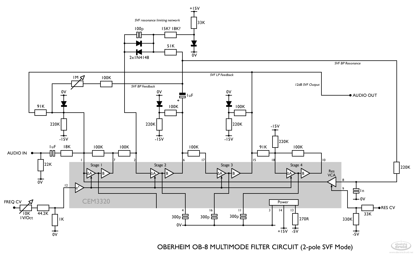
Note that both of these circuits include “left over” bits from the other which are still connected. If you were to build either circuit on its own, you could simplify them somewhat. The OB-Xa designs would be good examples.
Elka Synthex
The Elka Synthex does another version of the same trick, allowing the first two stages of the filter to be switched between high pass and lowpass responses. In addition, the output can be taken from either after the second stage or after the fourth. This is arguably technically simpler than the OB-8 since it doesn’t change the circuit’s topology so much, but it allows more different options.

The schematic for this is slightly intimidating, but once you start to break it down into the four stages, it’s not so bad.
The Synthex filter can produce the following responses:
Note that other configurations are possible that the Synthex doesn’t use. A 12dB lowpass filter could also be provided, as could an asymmetric bandpass; 18dB lowpass, combined with a 6dB highpass.
Craig Anderton’s Multiple Identity Filter
Ok, now we’re ready to tackle this, or as ready as we’ll ever be. I’m not going to repost the whole series of articles or the entire schematic diagram. You can look up the original Multiple Identity filter article here if you’re interested. Instead, let’s have a look at just one stage. After all, the other three are the same as this one.

Note that you could build this filter based on the SSM2040 chip too.The resistors values would be slightly different, and the lower resistor of the voltage divider (200R) goes to ground instead of -15V. Aside from these minor differences, the structure of the circuit would be identical to the CEM3320 version above. You can compare the CEM3320 Lowpass, SSM2040 Lowpass, CEM3320 Highpass, SSM2040 Highpass, CEM3320 Allpass stage, and SSM2040 Allpass to see how similar they all are.
The filter stage shown here has two switches in the circuit. SW1 switches the resistors at the input into or out of the circuit. SW2 switches the capacitor, either to ground, or to the input.
There are four combinations for the two switches.
- Both switches up: Highpass filter stage
- Both switches down: Lowpass filter stage
- SW1 down, SW2 up: Allpass filter stage
- SW1 up, SW2 down: stage disabled
The full circuit diagram also includes switches to select two different capacitor values (100pF or 1nF) and to select series or parallel routing of the stages. I’ve left these off for clarity.
How can I build one of these filters?
The AS3320 voltage-controlled filter (VCF) is a modern part which is functionally equivalent to (a clone of) the CEM3320, This chip is available in the shop. It will work in any of the circuits described here.
Original CEM3320 filter chips are not (currently) easy to get hold of, but they’re common compared to the extremely rare and ridiculously expensive SSM2040!
However, OnChip Systems have started producing the original Curtis ElectroMusic CEM3340 VCO design, so it’s possible they’ll re-release the CEM3320 too eventually. CoolAudio have also announced plans to clone the chip (as the V3320), so it’s possible that by 2018 we’ll be flooded with 3320 chips. Get building!
And what about those other types of multimode filters?
Multimode filters, Part 2: Pole mixing filters
Multimode filters, Part 3: State variable filters coming one year soon!
Comments and feedback
If you’ve got any comments or feedback drop us a line in the comments below, or get in touch through the contact page.
Hi I was wondering if there was a Spice model available for this chip for LTSpice or TI Tina?
I don’t know of one, sorry.
When you mentioned about OB8’s use of the CEM3320, you mentioned two addition CMOS chips were used,
“…. Consequently, changing the circuit requires 4 x SPST and 3 x SPDT switches, a 4016 and a 4053 CMOS analog switch chip. This means the filter uses one chip for the filter core, and two more chips for the reconfiguration!”.
But the schematics don’t show where these chips are to be used. Are these chips necessary to recreate multi mode filter?
The schematic shows the individual switches from each chip in a shaded square, and gives the pin numbers used in the original circuit.
It would be possible to recreate the circuit using mechanical multi-pole switches, but it’d be complicated because the control lines switch some switches on at the same time they switch others off. But with a bit of working out it could be done!
Thank you for clearing things up for me.
It’s possible with using switches and transistors to switch on and off in the same time.
Do you know what is the purpose of those two diodes on the Elka Synthex multimode filter circuit?
I’m not sure, no. There’s a significant bias on the points they connect to, so I suspect they allow bias current to flow when the switches are open. But I haven’t analysed it detail, so that’s only a guess.
Tom, thank you for this great article! To test my understanding: in the Elka Synthex schematic, should the 820K stage 3 feedback resistor actually be 82K, to match the other stages?
Going deeper with the CEM3320, I think your Lowpass filter stage description is missing an important detail. Per the CEM3320 data sheet (I found this expanded sheet with “Application Hints”: http://www.bustedgear.com/images/datasheets/CEM3320.pdf)
“The variable gain cell is a current-in, current-out device.”
(Formulas for IOUT, VT, and IREF here -> see PDF)
“As the input to the variable cell is a forward biased diode to ground, it presents essentially a low impedance summing node at a nominal 650mV above ground. The required input currents may therefore be obtained with resistors terminating at this input node.”
Noting that the summing node is .65V above ground is important when calculating the quiescent output voltage of each buffer, and this also tells us the purpose of resistors terminating at the input node (i.e. to source or sink current).
Further, I think it is inaccurate to describe RC and RB as a voltage divider. Reasoning: the variable gain cell is a current-in device, not a voltage-in device.
Quoting again from the data-sheet:
“In the D.C quiescent state, the buffer output will always adjust itself so that a current equal to IREF flows in to the input. For lowest control voltage feedthrough and maximum peak-to-peak output signal, the quiescent output voltage of each buffer, VODC, should be:”
VODC = .46VCC
Later, the data sheet helpfully lays out some guidelines for how to select RF, RC and RB, which clarifies the purpose of RB:
A) The gain of stages 2, 3 and 4 should be unity (where gain is a essentially a function of RF and RC)
B) With buffer outputs at the proper quiescent level, the total current into each input, IIN, should equal IREF
And in Lowpass configuration, all of stage 1’s quiescent IIN current is sourced from RF (assuming the input signal is centered around 0V), while stage 2, 3 and 4 source current from both RF and RC. Thus, to end up with a net quiescent input of IREF for stages 2, 3 and 4, RB is used to sink the excess current from RC.
—
Please let me know if the above sounds correct to you. I have no formal training in electrical engineering, I just have a knack for reading technical papers. Thank you for this excellent article, without which I would have not made it this far!
Hi! Thanks for the great article! I was wondering if I can make two independent low pass filters out of the 3320? I guess simply using two of the low-pass stages for each will do, but is it possible to have two independent VC resonances?
Thank you in advance!
No, all four stages are driven by the same control voltage, so they wouldn’t be independent. And as you say, you’d only have one VC resonance.
The chip you need is the AS3350, which is a dual SVF filter on a single chip. Both filters can be set up as lowpass if required, and they each have independent cutoff and resonance. Here’s a link:
AS3350 Dual SVF