
The Boss MT-2 Metal Zone distortion pedal is one of the most complex drive pedals there is, and has probably the most sophisticated (and least understood!) tone control circuit on any mass-market pedal. It’s also quite a divisive beast, with some loving it, and others hating it. It’s a great pedal for modifications – easily available, cheap, and rugged. This article is a technical analysis of the different stages in the pedal, finding out what each part does to the tone. This process should suggest various ways you can tweak it to get your own high-gain version of heaven.
First, take a look at the schematic. We’ll break it down into functional blocks, and to keep things reasonably simple, we’ll ignore the power circuitry and the typical Boss noiseless FET-bypass. That’s another thing for another day.
Boss MT-2 Metal Zone Schematic
Ok, reading from top-left to bottom-right, we’ve got the input buffer, the pre-distortion tone shaping circuit, the gain stage and clipping diodes, the post-distortion tone shaping circuit, the High and Low tone controls, and the sweepable Mid tone control. All this is finished off with an output buffer. See, I told you it was complicated! Let’s have a look at those parts one by one.
Input buffer
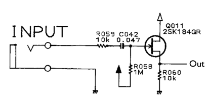 This is just a simple stage to get us warmed up! It’s a FET buffer. The input impedance is largely down to R058, so we’ve got 1MOhm. It’s connected to “black up arrow” which is the symbol they’re using for the 4.5V midpoint voltage. C042/47n is a AC-coupling capacitor (or “DC blocking”, whichever way you want to see it).
Pre-distortion tone shaping
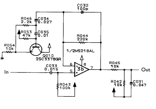 Now things start to get interesting! Our input signal comes in through C033/15n to the +ve input of the op-amp, which is biased to the midpoint voltage with R043/100K. These two components form a highpass filter with a cutoff at 106Hz, just enough to reduce any mains hum a little without heavily affecting the input signal. Op-amp 3b is a non-inverting amplifier, but instead of a simple potential divider to set the amount of feedback to the negative input (and hence the gain) there’s a lot of extra stuff and a transistor. The feedback resistor R044/220K is simple enough, and in combination with C032/100p, it gives a gentle 6dB roll off of high frequencies above 7.2KHz, which is about the top of the guitar’s range. You can check this 220K/100p calculation on the RC filter calculator page.
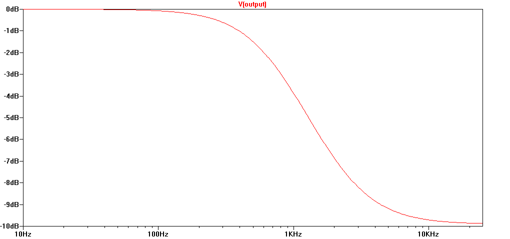
The “extra stuff” is a transistor-based gyrator stage. As usual, Rod Elliot has the best page about gyrator filters. Here it acts as a bandpass filter, centred around 1KHz. Either side of this, the gain starts to drop off. Additionally, R045 and R042 form a 10K/10K potential divider on the output of the stage, and R045 and C031 form a lowpass filter with a cutoff at around 340Hz. This rolls off the highs even more, and helps smooth things out a little bit.
This stage gives a notable “mid hump”. If you try putting a wah pedal in front of a distortion pedal, you’ll find you can alter the tone of the distortion by moving the wah. This is similar to what’s going on here – a peak in the frequency response is being created to boost mid-range and shape the sound of the distortion.
Gain stage and clipping diodes
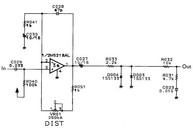 We start the next stage with an AC-coupling cap C029/33n. With R040/100K, that input cap forms a high-pass filter at 48Hz, plenty low enough to get all guitar tones. The gain is provided by another non-inverting op-amp, 3a. R051 and VR1 give a minimum and maximum gain of x2 and x252. C028/47p is small enough that even with VR01 at maximum resistance, it only rolls off the top end above 13KHz. Its role here is to limit gain for noise outside the audio band. Note that with a typical guitar input of around 1Vpp, there’s no way an op-amp running on 9V can provide an output of 252V when the gain is turned up to full. Instead the signal will get heavily clipped by the op-amp as it hits the power rails, usually at around 8Vpp for typical op-amps. Since different op-amps handle this differently, the choice of op-amp here might have some bearing on the tone, although given everything else that happens to our poor abused input signal, I doubt it’s a major factor. Following the gain stage is another AC-coupling cap and then a pair of clipping diodes. These are common-or-garden silicon diodes, so they clip the signal to +/-0.6V or 0.7V. That’s another heavy clip for our 8Vpp output from the gain stage. R033/2K2 helps to soften the edges of the clipping a little, as described here.
Looked at like this, the circuit is really a two-stage clipping circuit. Even at minimum gain (x2) there’ll be just enough signal to make the diodes conduct, so we can expect a light crunch. As the gain gets up to x8 or more, the op-amp will start to clip too, and its boosted output will be clipped hard by the diodes. And that gain control doesn’t just go to 11, it goes way up to 252. By that point, all that is left is a very heavily clipped signal.
After the diodes, we’ve got our raw distortion, with as much gain and crunch as we could possibly want. From here on, it’s a question of trying to sculpt that sound into our final tone. The first step in that process is the potential divider/ lowpass filter created by R032, R031, and C023.The filter gives a soft lowpass action and removes some treble. The maximum effect of this filter is only -10dB, so it’s not a huge effect.
Post-distortion tone shaping
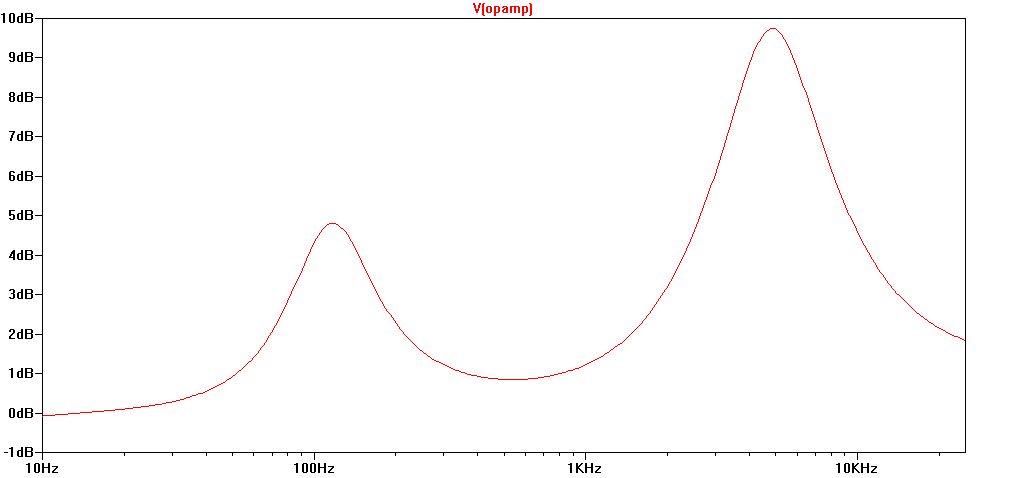
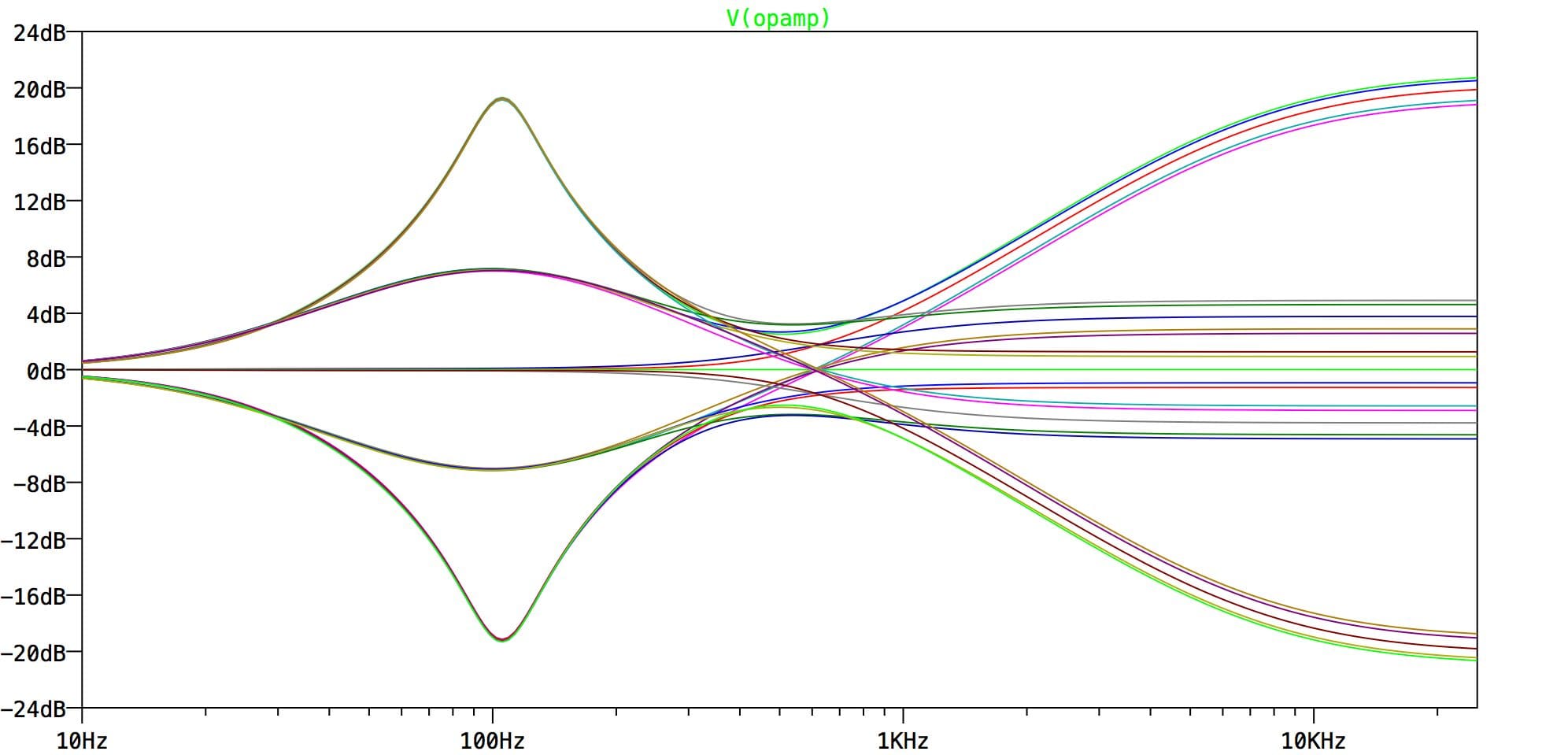
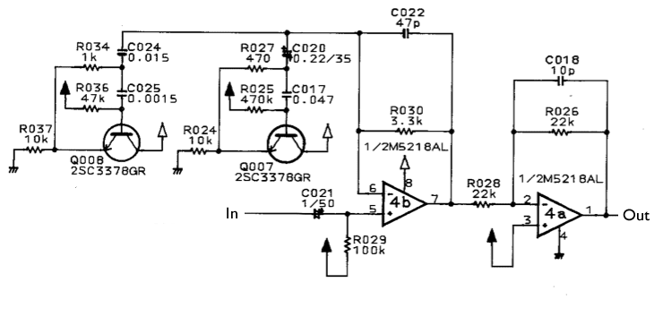 This stage shouldn’t be quite so unfamiliar this time around. It’s a more sophisticated version of the pre-distortion tone shaping circuit. This one has two gyrators, and therefore two peaks in the frequency response. We can plug the component values into the everso-helpful Bandpass EQ calculator over on Muzique.com and we get the following:
| R1 | R2 | C1 | C2 | Freq | Q | |
|---|---|---|---|---|---|---|
| Left Gyrator | 47K | 1K | 15n | 1n5 | 4898Hz | 2.2 |
| Right Gyrator | 470K | 470R | 220n | 47n | 105Hz | 14.6 |
Note the extremely high Q figure for the right-hand gyrator. This implies a bandwidth of 1/10th of an octave. In practice, the transistor’s gain isn’t sufficient to achieve such a boosted response. It may have been designed to allow for some slack from the transistor. Plotting the frequency response of the stage in LTSpice is instructive, and gives a reasonable result.
The final op-amp 4a is a simple unity-gain inverting stage. To be honest, I’m not sure what this is doing here. Perhaps Boss were concerned that the pedal should be non-inverting overall (is it? I haven’t checked) or perhaps they had one op-amp left over. Suffice to say, it doesn’t add anything, just flips the signal the other way up.
High and Low tone controls
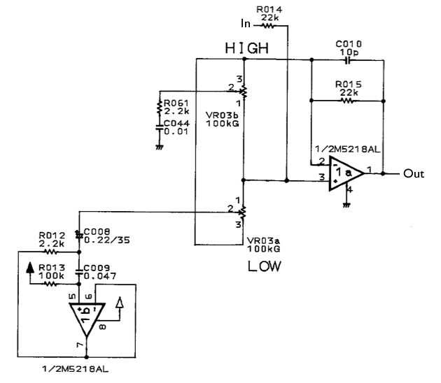 Now we get onto the tone controls. The first part of the tone control circuit is the High and Low controls. This is done with a pair of cut/boost-type controls. This circuit is related to the op-amp differential amplifier, and with the controls in the centre, the signals to the +ve and -ve inputs of the op-amp cancel out and there’s no overall effect. As the controls are moved away from the centre position, either the positive or the negative signal will dominate, and there’s a resulting cut or boost. This circuit can give +/-20dB, so it’s a substantial cut or boost too.
The High control is simpler, being just a resistor and a capacitor to make a high shelving. The Low control is another gyrator, this time with an op-amp as the active element rather than a transistor.
| R1 | R2 | C1 | C2 | Freq | Q | |
|---|---|---|---|---|---|---|
| Low tone control | 100K | 2.2K | 220n | 47n | 105Hz | 3.1 |
The Low tone control has the same 100Hz centre frequency as one of the post-distortion tone shaping gyrators, but this time it’s got a much lower Q, giving it a much wider, shallower action. It’s more of a broad brush, and not such a “peaky” sound.
Sweepable Mid tone control
 The second part of the tone control circuit is the sweepable Mid tone control. It isn’t a fully parametric EQ because although you can change the amount of cut or boost and sweep the frequency, you can’t change the “Q factor”, which determines the bandwidth, or how wide the effect of the stage is. We can call it a “semi-parametric EQ” if you like, but “Sweepable Mid control” is just as good.
The heart of the tone control is the Wien bridge network formed by C036/22n, C043/8n2, R048/2K2, R062/2K2 and the dual-gang pot VR02/50K. A Wien bridge network always needs a dual-gang pot to alter its frequency. If you want to know more about Wien bridge circuits, you could read the ESP page about Wien Bridge EQ. Most of the stuff about them deals with the Wien bridge oscillator, which is a standard sine wave oscillator circuit.
Boss managed to keep the Q response constant across the range of the sweep. This is probably why they chose the Wien-bridge circuit rather than use another gyrator. It’s hard to keep Q within reasonable limits when you make the gyrator’s frequency variable.
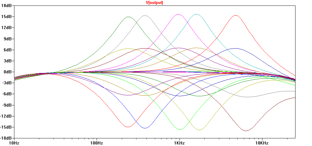
The “Mid” control gives a cut or boost of 15dB. Note that there is a slight asymmetry between boost and cut. The “Mid Freq” control goes from 240Hz in both cases, but when boosted the top end is 4.7KHz, whereas when cut it is 6.3KHz.
We should also note that the “Mid Freq” control response is a long way from linear. The plotted values above are 0, 5K, 10K, 30K and 50K for the Mid Freq dual-gang pot. If you’re building one, a reverse-log taper would perhaps give the best response. Good luck finding a dual-gang reverse log pot – it’s possible, but not easy.
These tone controls are one of the reasons why some people hate this pedal, and why others love it. The four controls (High, Low, Mid, Mid Freq) give you a huge tonal variety to explore, but also make it difficult to find your perfect setting unless you know from the outset what you want. This is a pedal which maybe doesn’t reward random knob twiddling. It’s a bit too complicated for that.
Output buffer
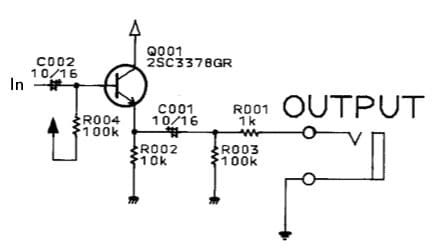 Phew! We’ve finally made it to here! Another simple one to finish off. This is a simple emitter follower buffer. R004/100K ties the base to the bias voltage of 4.5V. C002/10μF AC-couples the input, and C001/10μF does the same for the output. R003/100K ties the output to ground to prevent (ok, “reduce”) thumps when you plug in, and R001/1K protects the output against shorts and people getting the input and output mixed up.
Why does the Metal Zone sound like it does?
I’ve already commented on the sophistication of the MT-2 Metal Zone’s EQ, and it does give you a lot of options. But it’s not the only thing defining the sound of the pedal. The pre- and post-distortion tone shaping circuits have a massive influence, and beyond what you can tweak on the EQ, they are the sound of the pedal. Swapping the gain op-amp or changing the clipping diodes might have a subtle effect, but changing the frequency-determining components in those two tone shaping stages will give much more radical results. Whereas on many other distortion or overdrive pedals, the op-amp used or the clipping diodes have a major influence on the final output, in the MT-2 it’s really all about frequency response. It’s heavily shaped every step of the way, and those frequency responses determine the sound of the pedal, much more than diode choice ever would.
That initial mid-hump before the distortion, high-gain double clipping, and then the scooped-mid response after it give the pedal its tone. Add to that the high degree of tweakability that comes from the powerful EQ and you’ve got a successful pedal.
And that is the gory detail of the guts of the MT-2 Metal Zone. Thanks for reading and I hope it inspires you to have a tweak at this remarkable pedal, or maybe design your own with a little inspiration from those clever Boss engineers of the 1980’s.
Credits
This article owes a lot to the extremely helpful folks over at DIYStompboxes.com, where I raised my questions. Thanks to Paul R in particular for his help in understanding the post-distortion tone shaping.
Thanks for doing this writeup! I’ve always thought that this pedal has way more potential than people give it credit for; nice to see a similar argument and the analysis to justify it. Much appreciated!
I recently mod my MT2 by releasing R42 & R36 and lost both R’s when I was going to put the pedal into stock. So I exchange both for the same value as the schematic, I compared with another stock MT2 (I have at least three of these pedal) and I found out that lots of stock MT having different components value from the schematic. I also accidentally put C25 with same value with C24, but I tested it with the diode mod (I put D3 & D4 in series on the PCB hole of D3, and put another diode on the D4 hole with 1N9148). The final result was fascinating, well at least for my ears: higher level, more open in middle frequency, more raw distortion & assymetrical clipping. The fizzy fuzzy treble sound is bit lower than the stock MT2.
I’m going to find out other components which aren’t in the exact value with the schematic when I have time in the future and see if the results will be better.
It’s best as a preamp-watch Ola Englund’s video on it if you haven’t already.
Thanks for this breakdown! Very eloquent. I’m an MT2 fan and it completely blows the MT3 away. For a lot of guitarists I fear there are too many op-amp stages and EQ – there is a lot of negative feedback, filtered at that -it’s easy to get a very phasey scooped tone.
But it’s a great 303 mangler, listen to some chemical brothers!
Fantastic write up.. it really helped me unlock the sound I needed without relying on the often quoted mods suggested in the forums (which also create an unusable live sound based on most YouTube videos). Thank you for saving me from that horror!
Thanks! I’m glad it was helpful.
You have a dead link in the “Gain stage and clipping diodes” section. Fortunately you could replace it with an archive.org link:
https://web.archive.org/web/20160707235213/http://sound.westhost.com/articles/soft-clip.htm
Thanks for spotting that. The ESP audio pages have moved, so I’ll have to correct all the ESP links, on this page and elsewhere.
The new site is: https://sound-au.com
T.
Thank you for this EXCELLENT writeup; very accessible and transparent (unlike the stock MT-2 tone).
This was very helpful to show my students in my Audio Electronics class, and it’s motivated me to cut into my own old MT-2.
Question;
I’d like to disable the 1 pre- and 2 post-distortion gyrators.
Would you recommend I clip the C34 and/or C35, for example ?
It seems like a reasonable plan to me. Those stages are basically a non-inverting op-amps, if you ignore the gyrator. So clipping C34 out disconnects the gyrator and leaves you with a unity gain op-amp buffer, more or less. I’d certainly give it a try. If it didn’t work, I’d try soldering a wire across R044/220K, which then turns it into absolutely a op-amp buffer. The post-clipping gyrators can be disabled the same way, but certainly have a listen (and record a sound file for posterity!) without the first gyrator stage before you attack the other two as well.
Note that you’re definitely losing gain though (that first gyrator has a gain of *36dB* at it’s peak, so an alternative to soldering a wire across R044 would be to add a resistor from the R044/C034 junction to Vbias to give a flat boost across the whole audio range.
Another approach would be to experiment with a few values in the Musique.com gyrator calculator and make the gyrators very low Q (wide and shallow, instead of very peaky). That would effectively boost most of the spectrum, but without becoming completely flat.
Let us know if you come up with anything good!
Tom
i’m very confused about the mid freq knob, sometimes i get the tone and on the other time it’s stressed me out, can you explain the mid freq knob function into the detail ? thanks
The “Mid” control is sweepable – that is to say, it’s not at a set frequency. The “Mid Freq” control sets where it takes effect, from about 300Hz up to about 7KHz. That’s a very wide range. The other Mid control then sets the cut or boost at the frequency selected. The graph in Mid Tone control section visualises what’s going on – any of those lines are possible responses from this section of the circuit.
HTH,
Tom
Ive never really understood why people would buy a Metal Zone and then expect, and desire it to sound like tube screamer, all whilst the gain is ‘dimed'(on mt-2) inevitably.
In the future when people berate the pedal I will cite your, great site and informed article and drop some knowledge on them suckas.
Truth be told.
Myself MT-2 has always been a favorite.
I love the hyper drive gain, which unlike many other so called ‘hi gain’ pedals, the gain really should rarely if ever de dimed. Its simply too much, for most situations….and I love gain more than most. But, even with more modest gain settings and careful eq use I think just about anyone should be ale to get a punishing metal tone out of the ol MT-2.
This is really similar to what Dimebag did with his entire rig, boost the mids into his amp then use a parametric eq to scoop the mids after the amp.
The curve of that post distortion EQ remins me of james hetfield’s settings on the graphic EQ of his favorite amp.
cool stuff
Great! Would it be possible to wire the eq to shape the sound before the distortion? Would that work even with the signal inverting eq input?
It would be possible to hack the circuit to put the EQ before the distortion, yes. I don’t know how easy it would be. It’d involve cutting some tracks and wiring some jumper wires in here and there.
It will certainly work despite the “extra” inverting op-amp, and it shouldn’t affect anything, since you wouldn’t be increasing or decreasing the number of inversions the signal undergoes – just shuffling them around!
HTH,
Tom
I’ve put the EQ before the gain section and it sounds brilliant.. I put the sweepable mid-range pre-gain but kept the treble and bass controls post-gain. This combination makes the pedal very useable in a live set-up (using a valve amp pushed to break-up); IMO this only works properly if you disengage all the gyrators and start with a good quality flat base tone. I will put the details of the entire mod I did below as I believe it is too good to keep to myself.
Excellent article. I’m experiencing some of these issues as well..
Thank you so much for the breakdown Tom. It was super interesting and informative.
I’m working on an homebrew mod and I was wondering what would be the best way to diminish the amount of gain in the gain stage. Reducing the value of R51? Also if I jumper the the buffer between R28 and R14 can I jumper also one of those resistors?
Thanks again.
Reducing the value of R51 *does* decrease the gain, but it’s so small compared to the 250K pot VR1 that it’s not really worth it. A better course of action is to *increase* the value of R41 up from 1K. The total gain here is:
gain = ((VR1+R51) / R41)+1So doubling the value of R41 to 2K2 would halve the maximum gain and back things off quite a bit. This would make sense to do if you find you only ever use settings in the first half of the Dist knob’s rotation.
HTH,
Tom
Transparent Distortion mod with Adjustable Drive Character.
After various incarnations, and a couple of wasted pedals, this is the definitive mod for the MT-2 in my opinion (of course I’m going to say that) and what better page to share it on! You do not need to buy any more components for this mod; you just need a soldering iron, solder and some good quality wire.
The main points I set out to achieve:
1. Good quality transparent base tone when tone dials at noon – (EASY)
2. Less compressed, dynamic sound with good pick articulation – (TRICKY)
3. Flexible sound with different guitar/amp set-ups – (HARD, but worth it)
4. Improved noise floor – (probably UNNECESSARY)
This was achieved by removing a shed-load of components and switching the sweepable mid-range to in front of the gain stage. Ideally you need to start with a first or second generation MT-2 (M5218AL ICs) as these sound best in my opinion:
1. Good quality transparent base tone when tone dials at noon – (EASY):
Remove: C034, R042, C031, C024, C020, C023, C010, C026
This disengages all of the gyrators and the low pass filters between, and during, op-amp stages. It refines the top end of the distortion and provides a good base tone. Please note: this will decrease the gain of the pedal. This sounds great with bridge pick-ups but is a little too flabby-sounding with neck pick-ups for my tastes. The third stage tightens this up and recovers the gain nicely.
2. Less compressed, dynamic sound with good pick articulation – (TRICKY):
Remove: R033, D004, D003, IC4
Bridge: gain stage side of R033 gap to point 1 of IC4 gap
I personally like the sound of op-amp distortion, particularly the M5218AL, and feel that the diodes add a nasal character. Removing the diodes boosts the output significantly too, which is great for pushing a valve amp to oblivion. I experimented with various diode combinations (symmetric/asymmetric +/- silicon/germanium) before removing them altogether; the sound is much less compressed and the pick articulation is better as a result.
3. Flexible sound with different guitar/amp set-ups – (HARD, but worth it):
Remove: C033, R043, R045
Remove and keep (note the polarity): C011, C005
Bridge: (a) signal side of R043 gap to mid-range side of C011 gap, (b) mid-range side of C005 gap to signal side of C031 gap
Connect: (a) capacitor from C011 to C033 gap (same polarity as earlier), (b) low/high side of C011 gap to output side C005 gap via the C005 capacitor saved from earlier (same polarity), I mounted this on extension leads
This puts the sweepable mid-range in front of the gain stage and lets you control the character of the distortion (dial in/out the “honk”); it is the key to this mod’s versatility. It will make single coils sound like humbuckers and vice versa, as well as outrageous sounds I have only ever got by stacking gain pedals together.
Keeping the high and low controls after the gain stage makes this pedal useable in live situations: dialling out the bass can help you to be heard without sounding louder. Keeping control over the presence helps add clarity when playing with a band.
4. Improved noise floor – (probably UNNECESSARY):
Remove: Q007, Q008, Q010
This was partly done by removing IC4 earlier, but if you have the soldering iron out you might as well remove these as they are not doing anything but putting noise to ground.
I had great fun developing this mod, the information on this page was invaluable in the design process. Thanks Tom! This pedal is now my drive pedal of choice, it easily trumps all the other Boss distortion pedals and a good number of boutique overdrives and fuzz pedals I own.
Very interesting, Toby. Thanks for sharing it.
any way you could post an image of the board so i can figure out where exactly you are talking about putting the jumpers for step 3?
In my experience, diode-to-ground configurations tend to have the characteristic that some of the unprocessed clipping sound is still heard through all filters and level controls. DS-1 for example. So try unsolder the diodes and connect them to pin 2 and 3 of op amp 3a. Yes, this is a tube screamer configuration. But it allows the tone controls to do their job fully.
Changing to tube screamer configuration is valid enough if that’s what you want to do, but I’m afraid I can’t agree with your analysis. The sound is clipped after the diodes-to-ground. There’s no unclipped sound in the signal.
Does anyone know if it’s possible to mod an MT-2 to have the mid EQ frequency sweepable via external expression pedal?
It would be pretty difficult because the Mid Freq control is a dual-gang pot. It might be a customised taper too. In the original pedal, it’s part of a special concentric pot with the Middle level control – so the single pot has *three* sections!
I was just wondering how the sweepable mid control really works because the filter seems pretty normal until the frequency shifter is involved. I’m pretty sure the op-amp on the right is a voltage follower but really not sure how that fits with the Wein bridge network. Any tips?
The op-amp on the right is a voltage follower, so you’ve got that bit right! It’s there just to separate the cut/boost control from the wein bridge network. Otherwise they interact a bit – it’s not too bad though, and the ESP site I linked in the article has plenty of examples without the buffer. I definitely recommend that article if you want to know more:
ESP Wien Bridge Based Parametric Equaliser page
For the wein bridge network itself, think of it as a potential divider with the input coming in at the top from that buffer op-amp. At low frequencies, the capacitors can be regarded as open circuit, so the resistance of the top of the potential divider is much larger than the bottom (since it contains an open-circuit cap). So no output signal is produced from the mid-point of the bridge. At high frequencies, the capacitors can be regarded as short-circuits, so the resistance of the bottom of the potential divider is now zero (since it is shorted to ground by the cap). So no output signal is produced from the mid-point of the bridge then either! So what’s going on? How does it ever produce anything?!? Luckily for us, those are just the extreme cases, and in the middle range of frequencies, there’s a point at which the impedances of the top and bottom of the bridge are equal and we get an output – so it acts as a bandpass filter. Does that help make it any clearer?
Yeah, that’s great thanks! After going through it that makes a lot more sense, but I’m still a little confused about the interaction between R050, VR02b, R049 and C037 and how C038 is used to feed the signal back to the first filter. Thanks again!
The low tone control gyrator computes to be 105Hz. Yet the graph of the low tone control right above those computations show the low tone control affecting 350Hz at maximum boost or cut, with the center frequency maybe moving down to 150Hz for small amounts of boost or cut. There don’t SEEM to be any other components in the tone circuit that could be affecting the resonant frequency of the gyrator. Explain?
Well spotted! That’s an error. I checked the LTSpice simulation file, and it turned out the 100K resistor was only 10K, hence the frequency shift. I’ve now corrected the graphic. Thanks for bringing it to my attention.
Hi Tom. Amazing analysis of the MT-2 circuit! This inspired me to make a mod to atenuate the pre-distortion mid boost which I find really annoying, with great results. I also made a video tutorial on Youtube here: https://youtu.be/c3qaJAIzU14 with before and after sound samples and added the link to this page in the description so more people can find it. Thanks and keep up with this great job!!!
Existe como colocar um potenciômetro interno nele para regular a distorção do minimo ate o máximo que este pedal pode dar?
Com sua permissão, respondo brevemente em inglês para que todos possam ler a minha resposta
Is there any way to put an internal potentiometer in it to regulate the distortion of the minimum to the maximum that this pedal can give?
Hi Paulo,
The gain stage is a standard non-inverting op-amp, so the gain is (R1/R2)+1. The value of R1 in this case is R051 plus whatever VR01 is set at. R2 is R041, so 1K. So the minimum gain is (1K+0K/1K)+1 = 2. The maximum gain is (1K+250K/1K)+1 = 252. It’s hard to adjust the minimum gain without also affecting the maximum gain, but one simple choice to get more variation would be to replace R041 with a trimmer. If the trimmer value goes below 1K, then the gain goes up, and if the trimmer value is larger than 1K, they both go down. Since the gain at the minimum end is so much smaller, changes to the minimum will be less pronounced, and the equation shows that the gain cannot go lower than 1 whatever we do.
Putting a 4K7 or 10K trimmer in place of R041 would allow you to significantly alter the maximum gain of the pedal without doing a huge amount to the circuit and without changing the minimum gain a great deal (the worst case is it will be x1 rather than the current x2 – not a huge change).
HTH,
Tom
I have 2 questions.
1. About c20 and c24… I know cutting one out makes it brighter and cutting the other makes it darker, but not sure which is which. Simply put, which would I remove to darken it up?
2. Is there a somewhat simple way to add a surface mount 3 way toggle, so I could select between the 2, with both engaged ( normal) in the middle position?
These are two of the capacitors for the post-distortion gyrators. C24 is the higher peak, C20 is the lower peak. Remember that taking out a higher peak will probably make the sound darker, and taking out a lower peak will probably brighten it. But these are peaks, not overall tone controls, so it isn’t really as simple as “brighter” or “darker”.
I can’t think of a way to do the switch selection you suggest, except with a (somewhat rare) 3 position DPDT, like I used in the FilterFX pedal.
Hi,
I recently got a MT-2 used from a friend and found that the pedal sounds too “nasal” to my taste. No matter what I do with its tonal knobs it seems like this nasal effect just don´t go away.
So:
1- What are the options to get rid of that nasal tone or at least attenuate it?
2- What is a simple way to reduce a bit the general gain of the pedal (turning it to a more versatile drive)?
Thanks
“Nasal” suggests a peak or peaks in the frequency response, so you could try disconnecting either the pre- or post-distortion gyrators.
The pre-distortion gyrator would be disabled by removing C034. The post-distortion gyrators are C020 and C024. That still leaves the actual tone controls unaffected, so you still have a lot of scope for tonal modification.
The gain could be reduced by increasing R041/1K. Experiment with 2K2, 3K3, 4K7, or even 10K and see what you like.
Good luck! Let us know how you get on!
Removing C034 drops the gain and/or volume dramatically. The pedal turns to an almost non usable effect.
Removing C035 gets rid of the nasal tone (yeah!), but puts some hiss in.
So far I let only C035 out and changed R041(1k) for a 18k trimpot that I canibalized from a dead pedal, set around 3,5k. This gave me a fairly versatile pedal. With the gain knob below 9 o´clock it´s almost a clean booster/equalizer pedal. Turning the gain knob clockwise from there it goes from a low gain overdrive to a nasty distortion similar to the original metal zone!
Now I´m thinking about putting this “pre gain” sort of control outside the box in order to make the adjustments easier, and if so, I´ll have to choose the best way to do it: housing the trimpot inside the battery compartment some way or using a full size pot.
What do you think?
Thanks
https://youtu.be/c3qaJAIzU14
Hear this mod and see the physical steps in performing this mod.
OP could try to find out if the peaky response causing “Nasal” effect is caused by pre EQ or post EQ.
Way to do this is to play the guitar strings slowly, one string at a time, with one finger barring all strings at different frets. Do this up and down the fretboard
Look for : did volume change for some strings at some positions?
Did amount of fuzziness change for some strings at some positions ?
This info will guide you on what to do next.
Brother Tom,
Would reducing the Q of the pre dist shaped reduce the nasal tone?
Could you suggest component changes to reduce Q of pre dist gyrator?
You can experiment with the values in the muzique.com gyrator calculator.
Trying a few things, it looks like increasing C034 to 47n and decreasing R052 to 22K reduces the Q from 2.8 to 1.4 without affecting the frequency much (it goes up by 100Hz only). You could do better, but it’d probably involve changing more components.
https://youtu.be/c3qaJAIzU14
Hear this mod and see the physical steps in performing this mod.
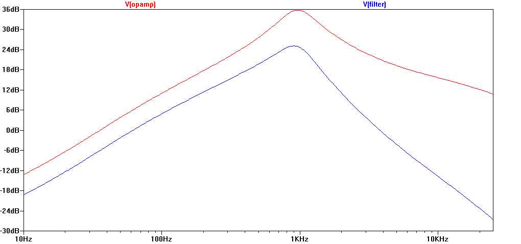
I tried to match the “Metal Zone pre-distortion tone shaping: blue line is response after the lowpass filter” so that I could program them into my Yamaha MagicSstomp. After some rough measurements of the blue curve shown here and some rough curve fitting for filters, I came up with two sets of filters, each is an attempt to match the blue curve with differing levels of success.
Set 1:
F :50 Hz
Q: 0.63
G: -12 dB
F:300 Hz
Q: 0.21
G: 12 dB
F: 1000 Hz
Q: 0.79
G: 12 dB
———————-
Second sent that also tries to match the same blue curve
F :62 Hz
Q: 0.36
G: -12 dB
F:747 Hz
Q: 1.12
G: 12 dB
F: 4760 Hz
Q: 0.63
G: -12 dB
These are the best fits given the constraints of number of bands, F and G of the Yamaha MagicStomp.
This data might help someone trying to simulate the MT-2 on software or programmable hardware.
And here are the best parametric equaliser settings to recreate the TOTAL post distortion frequency response curve for “Heavy Metal” settings proposed by Boss in their manual.
High : 3 o’ clock
Low : 3 o’ clock
Mid Freq : 2 o’ clock
Mid : 11 o’ clock
TOTAL post distortion response = low pass after distortion + double peak filter + High/Low + Mid sections
F : 125 Hz
Q: 0.53
G: 12 dB
F : 4565 Hz
Q: 0.48
G: 12 dB
F : 5175 Hz
Q: 0.54
G: 2.41 dB
It’s really a SMILE curve with bottom at around 750 Hz, with peaks at 120 Hz and 5000 Hz that are about 10 dB higher than the bottom. Somehow that was expected since most literature says “pre Frown , post Smile” equalisation for Metal. The frown is quite “Peaky” while the smile is relaxed.
The Metal settings on the AKAI D2G G-Drive ( innovative box with predist EQ, dist, Post Dist EQ) also are “pre Frown , post Smile” with a peaky pre Frown and gentle post Smile.
on the input buffer. you have to connect a 100K resistor (as the schematics drawn) from fet output to bias (1/2V) or else, the 4.5 virtual ground wont happen.
That’s true, but I mentioned in the introduction that I was ignoring the FET bypass circuit. For the buffer, the 1M resistor R058 provides the bias.
How to mod MT2 to fuzz pedal?
Not much point, I’d say. Most fuzz pedals are *way* simpler than this beast, so it makes more sense to build a fuzz from scratch rather than try and turn this into something it was never intended to be. Have a look at this:
http://circuit-bent.net/category/fuzz-face-schematic
Great article! Pleease update the link to elliot sound “ESP page about Wien Bridge EQ”, the site has moved. New link is https://sound-au.com/project150.htm
Thanks, link updated, again. That site moved before – see comments above in December 2016.
Thanks for the article!
I have a question. Is it possible to mod the post eq session so that the “low” control acts as a high pass filter instead of a band pass/stop filter? Will it make the pedal better or worse?
Hi, thx for the great article.
can you tell me which components that responsible for the overall high frequency of MT2.
I want to get rid of that high frequency that cannot be eliminate by tone knob and by removing the C35, C25, and C24. thanks.
I don’t think what you’re hearing is a “high” frequency. The High tone control provides 20dB of cut to all high frequencies, so if that isn’t altering the tone you’re hearing, what you’re hearing isn’t a high frequency.
Removing C24/C25 would take out the high peak of the ‘mid scoop’ post-distortion EQ. Taking out C35 alone will turn the pre-distortion EQ into an amplifier with a bass roll-off like a tube screamer, but I haven’t checked the frequency.
thank you for the reply,
When lowering the mt2 high tone knob I can still hear that “high frequency” sound, and when I turn the knob up, to my ear it only boost certain high frequency and I believe it is below that “high frequency” i heard which still exist but not boosted. That means, to my ear, the high tone knob doesn’t have any effect to that “high frequency” i heard. So I assume there is some part somewhere in MT2 that can be change to cut that “high frequency” out. I suspect that “high freqeuncy is above 10khz.
but may be you right, it is not high frequency. maybe it is the characteristic of mt2 distortion which to my ear sounds like an annoying high frequency fizzy sound.
I wondered if perhaps the mods have made some of the op-amp stages unstable and there’s a high frequency oscillation, but checking the schematic, it’s unlikely.
You could try increasing C022/47p and C018/10p to roll-off the high end a bit more. That should help tame fizziness.
thank you, i will try that and inform you the result.
I tried increasing c22 and c18, I found increasing c18 make the sound little bit dull and the volume drop. changing c22 give best result, i change it to 68p, the high frequncy is better to my ear, the fizzines decreased.
by the i try using mylar and ceramic, i found that the mylar tend to soften the high, i don’t know the right words for it. I prefer to use ceramic cap for c22.
this is the sample sound of my mod
https://youtu.be/GOW42WRtymc
hi, thanx for this excellent article..
today I received an used mt-2 which I intend to use mostly for recording.
too bad when I got to tweak the mid controls.. nothing happened
really nothing, no matter how I set mid freq and middle (I know how a semiparametric. should work)
any Idea of what could be wrong? probably just the pot itself i guess, then as u said, finding a replacement won’t be that easy..
actually I relized that messing (slightly moving) with the ps ac imput jack I can get the mid control to work, or stop working again…
that is both feeding the pedal from a battery or with an external ps.
weird!
That sounds like either a crack on the board breaking/making a connection, or the jack shorting on something. Definitely mechanical, rather than electronic.
I just came back to the page and realised that you had answered 🙂 THX
it actually was one of the wires inside the flat cable that connects the two boards, I finally spotted it and fixed the problem with a bridge.
lost 2 hours on it, so the guy whom I bought it from wanted to gimme the cash back, but I just asked for a halfprice refund. in the end i got a working unit for 20Euros and I actually like the stock sound, but now I have to buy another one to start modding around..
Thank you for this analysis. I’ve had my MT-2 for over 20 years and always enjoyed the way it sounded through my Peavey Century head, although it was a noisy pedal (RF like I’m next to a neon light- especially with the distortion pot halfway and up). I always wanted to get more of the “Chainsaw” distortion like the HM-2 provided for much of the music I grew up listening to. After recently building an HM-2 clone I decided to look into modifying the MT-2. This analysis proved indispensable.
I have been able to mod this pedal into something quite enjoyable, and learned quite a bit, by removing/replacing/adding a single component and playing it each time. It can chainsaw, but with its own unique sound: especially with the mid controls. Through all of this progress I seem to not be able to overcome the noise that I feel has always been the caveat with this pedal. I’ve always read or heard how inherently noisy this pedal is from others but, I wonder, if maybe there’s always been something wrong with my pedal. Is there any advice you might give in diagnosing where it’s coming from and how to minimize it? I suspect something can be done as my recent HM-2 (3xM5218L’s) build is a very quiet pedal in comparison. Could an IC or transistor be causing the noise?
Also, I noticed IC4 is a 4558 in mine. Is this an equal replacement for a 5218?
“PRE-DISTORTION TONE SHAPING” ALSO DISTORTS HEAVILY !!!
Dear Tom, Thanks for this great analysis !
The graph of the “pre-distortion tone shaping” section built around IC 3B shows a gain of 36dB at 1Khz peak
This means that a 1Vpeak guitar signal at 1Khz will demand that the IC 3B output 63 volts peak
Since this is not possible, the IC 3B will saturate and clip the signal. Actually since the gyrator imposes a frequency dependent gain, all 1Vp signals from 110 Hz to 20Khz will be distorted due to rail saturation of 3B, in different degrees dependent on the frequency (Frequencies near 1Khz will distort more since gain is higher there)
Hence there are at least 3 places where distortion takes place in the MT2 ( Not two as implied in the article)
A) “Pre-distortion tone shaping” stage 3B also distorts very heavily (It should not be called “Pre-distortion tone shaping” since it distorts too)
B) DIST 3A is mostly being fed rail to rail signals from IC 3B so, even with a very slight gain, it will also saturate to rail
C) The hard clipping diodes are also clipping all the while since most of the time, IC 3A is outputting square waves of 4Vp (rail saturated signal)
Hence the MT2 is a 3 stage clipper, not 2 (assuming that other stages after hard clipping diodes do not distort)
The article states regarding 3A “Note that with a typical guitar input of around 1Vpp, there’s no way an op-amp running on 9V can provide an output of 252V when the gain is turned up to full. Instead the signal will get heavily clipped by the op-amp as it hits the power rails, usually at around 8Vpp for typical op-amps.”
However this stage 3A is not getting fed by the guitar with 1Vpp guitar signals. It is getting fed with the 4Vp rail to rail saturated signal from 3B. Even a slight gain of 1.01x will make this 3A also rail saturate due to extremely high signal it is fed from tone shaper 3B. Hence it is almost always rail to rail saturating as well, even at low gain levels.
The MT2 is more complex and fun than we imagined earlier! Taming the gain down needs mods at 3B as well as 3A
PS : I measured the 3B tone shaper clipper 3B characteristics from your SPICE simulation as :
Gain 63x at peak
Q of 1.66
F of 960 Hz
Thanks Vivek!
https://blog.audio-tk.com/2021/02/09/analysis-of-the-boss-mt2-metal-zone-pedal-2/
Here’s another analysis of the MT2.
This author also found that the “Pre-distortion EQ” creates distortion due to its huge gain.
As you explained so well, the peculiar sound of the MT2 is caused by the interaction of tone shaping and distortion created at multiple points within the circuit.
Since it has been shown that the “Pre-distortion tone shaping” stage actually creates a lot of distortion,
The filter made by R045, R042, C031 cannot be seen as part of the pre-distortion tone shaping circuit. It is not technically correct to lump this filter with the response of the earlier stage and plot it out together. The associative law of LTI circuits is broken when there is a non-linear stage in the middle.
In fact, R045, R042, C031 are part of an inter-stage filtering process, after one stage that creates distortion and before another stage that creates distortion.
It is normal to cut high frequencies created by one distortion stage before sending to the next distortion stage.
hello. topic for me thanks kelly
Great article!
Do you happen to know what the standard/custom switch on the Waza version of the MT-2 changes?
Sorry, I don’t know. I’m sure someone somewhere on the interwebz is reverse-engineering the Wazacraft version as we speak though! That’ll be information that’s out there very soon, no doubt.
i get it now 🙂
I think what I’d really like to do, and what would help dial in the sounds I want more exactly, would be to take the guts out of this box and install them in a bigger box with six-inch sliders instead of tiny dial pots. That way it could be more clearly labeled and controlled, as a small tweak on any of these dials creates a big change. You have any advice for a project like that?
Such a thing would be doable, for sure. There are plenty of people who’ve cloned the circuit. One point to note is that the original Mid-Freq pot has some strange taper (I can’t remember – Rev-Log?) and using a linear pot will change the feel a bit. But with larger knobs, you’d have more control anyway, as you say, so maybe it’s not too important.
Hey, thanks for all these precious info!
I really like the sound of the pedal without C35.
I’ve recently removed C25 and changed the C44 from 0,0104 to 0,0223, which makes the trebble more usable in my opinion.
@ Tom :
I am very happy to come today on this extremely useful page to share my experience.
I’ve always wanted to transform this metalzone, whose grain I appreciate, into a more rock and more versatile pedal.
After several attempts at removing/resoldering capacitors, my final choice was to remove C35 and C25. I quite liked the result but there was always something that bothered me, the sound was always too “full” and some unpleasant frequencies still seemed to be present, the sound aggravated my ears after a while.
The revelation came to me the day I said to myself for fun “why not test my metalzone in transparent overdrive?”. I set the gain to zero and completely cut the bass and treble, with the mids at noon and the level fully. I then found that the pedal sounded surprisingly good, like a somewhat “dry” tube screamer. Then I realized that by pushing the gain, the pedal went into a very interesting distortion, which sounds incredibly good on my marshall type preamp.
I think I really managed to make this pedal sound like I imagined, it’s a real satisfaction. Thank you very much for everything this page has taught me.
@Christopher :
In view of the circuit, I think it is indeed a very good idea to change C44 as you did (cutoff at 3.2kHz instead of 7kHz).
This is of no interest in my use (my settings are radical) but I think it would be useful for users looking to keep a full distortion.
If the gain knob is at 3 o’clock, what is the decibel gain?
Sorry, what is the voltage gain if the gain knob is at 3 o’clock. Is it 250 almost near to x252?
That’s actually pretty difficult to work out. Most pots have a 300 degree range from one end to the other. In “clock” terms, that’s from 7 o’clock (minimum) to 5 o’clock (maximum). So 3 o’clock is 8/10ths or 4/5ths of the way around. But most gain pots are logarithmic, so that’s 4/5ths of the way round a log pot…sigh! Sorry, it’s too late for me to work that out right now, but I hope that shows you why it’s not obvious!
Hi I used your analysis to make a DSP version of this!
It sounds okish – thx for all your hard work, I put this website line in the src code as credit – hope you don’t mind – I’ll take it out if need!
https://github.com/shabtronic/Chug-Zone
Shabster!
Wow, good effort! Something this fundamentally non-linear is a pretty difficult bit of DSP to do well. Keeping the harmonics and aliasing under control is going to be tough, I’d have thought!
And thanks for the credit, that’s appreciated.
You’re welcome – thanks for your hard work and sharing the info!
Aliasing is pretty simple with Guitar distortion DSP – just oversample 8x – interpolate and rectangular filter is enough to be usable. Tho I’ve tested before to get the spectrogram completely clean of any aliasing (-90db) and it takes at least a 1024 sinc filter – which is a HUGE amount of DSP time.
Thank you for taking the time to make this contributions!
What values do you recommend to make this pedal work with bass?
I know I should start with modding the gyrators, but it got confused on the Q section, what values would you start with?
TIA
I don’t know, you’d need to experiment a bit. As a “first guess”, I’d lower all the frequencies by an octave, but make sure that the Q values don’t change. That puts things more in the right range for Bass.
It might well be that you don’t want things as peaky for bass (or maybe more peaky, who knows?) but that’s where the experimenting comes in. The controls are very versatile on this pedal, so you should be able to dial it in pretty well.
https://guitarpedalsvisualized.wordpress.com/2023/03/05/boss-mt-2/
Found a site that shows some waveforms of the MT-2
Thanks Vivek!