
This article is a follow-up to my 2015 post about the distorted pitch shift you get when applying modulation to a BBD clock. In fact, it’s more a replacement than a follow-up! Since I wrote the original article, many people have written to me with thoughts and comments, and their ideas combined with the fact I never quite felt like I got to the bottom of it has meant that I’ve never really stopped thinking about it. But now I feel like I’ve finally completed the work that that article started (hey, it’s only taken a decade!…), and I’d like to take you through it here.
What is generally assumed is that if you modulate a delay line with a sine wave, you’ll get a sine wave variation in the pitch at the output. If you use a triangle wave, you get a triangle wave, etc etc. This is not at all true. To say that the real situation is “non-ideal” understates the case considerably! If you use a square wave to modulate the pitch, the output sound may not have two pitches that it jumps between, but can have three!
How does a chorus work?
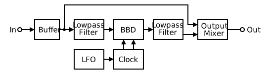
First, let’s have a quick look at the structure of a typical chorus unit and some of the parameter ranges that they use.
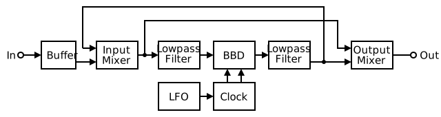
The signal comes in through a buffer. The dry signal is then taken off to the final mixer. The delayed signal passes through an anti-aliasing filter, the BBD, and a reconstruction filter, and then is mixed with the dry signal. The BBD is driven by a clock which is modulated by an LFO. Some chorus units add 570/571 compander stages around the filters and BBD part of this to reduce noise. A simpler but less effective alternative that you see more commonly is to apply pre-emphasis at the buffer stage and then use matching de-emphasis in the mixer stage. A flanger is basically the same structure as this, but with the addition of feedback, as shown below. This extra feedback path changes the sound, but it doesn’t affect the LFO, the clock, or the BBD, so for the purposes of this article flangers and chorus are the same.
What sort of clock rates and LFO speeds do chorus pedals use?
I’ve gathered details from circuits I’ve come across and generally chorus uses pretty short delays, mostly under 10ms. The classic CE-1, for example, uses delays between 1.3msec and 4msec, which is shorter than many. Dod’s FX-60 covers 5-8msecs, and the Maxon CS-9 covers 3.2 to 8.5msecs, and these are very typical. Chorus with slightly longer delay is possible, and gets more into a Pat Metheny / Kurt Cobain type of sound.
The clock frequencies vary more because different pedals use different BBD lengths. Chorus pedals have been built using BBDs from 256 stages all the way to 2048 stages, so the clock frequencies used (and bandwidths available!) vary widely. The more stages you have, the faster the clock has to run to get the same delay (but this can improve the signal bandwidth, so it’s not always a bad idea).
LFO frequencies are not so variable. A slow rate of 0.1Hz (a ten second period) to a fast rate of 10Hz covers pretty much all existing chorus pedals, with many limiting themselves to some central portion of this range. The Maxon CS-9 we already mentioned only goes from 0.3Hz to 3Hz, for example. Flangers tend to allow slower sweeps, with many going down to 0.1Hz, and some going even slower.
Delay Time and Clock Frequency
If you look in a BBD’s datasheet, the delay time is related to the clock frequency by a simple equation:
delay_time = number_of_stages / clock_frequency x 2
The important thing to note here is that the delay time is inversely proportional to the clock frequency. There’s a 1/x relationship between them, and 1/x is not a straight line!
Different types of Clock Modulation
We can see 1/x bending if we linearly modulate the clock frequency with the LFO. The resulting delay time is not a straight-sided triangle, but gets bent. Below is a demonstration. In this example with a 1024-stage BBD, the maximum LFO depth is +/-30KHz around a base clock frequency of 50KHz:
Of course, linear modulation of the clock is not our only option. Typical synth VCOs use a exponential “Volts per Octave” character. Perhaps we could use a 3340 VCO chip as a BBD clock to get a better result? You can also experiment with this option on the demo below. In this case, we have to change the base clock frequency to 40KHz so that we can go down an octave to 20KHz and up an octave to 80KHz.
The curving of the clock frequency improves the shape of the delay time, but it doesn’t cancel all the 1/x bending. Instead, we need to think about the equation we’re dealing with. We know the delay time is inversely proportional to the clock frequency, so it must be proportional to the clock period. So instead of modulating the frequency, we should modulate the period. For this final option, we use a 32KHz clock which has its 31.25us period modulated by +/-18.75us.
You can see that this “pre-bend” of the clock frequency cancels the bending in the delay time, and we get a nice clean triangle wave modulation of delay time. For this reason, many classic chorus pedals (particularly by Roland/Boss!) use this type of modulation. Have a play with the various options and see how different ways of modulating the clock with the LFO change the shape of the resulting delay time.
I should mention here that the equation we’ve just used for these demonstrations assumes that the clock frequency is fixed and this doesn’t actually work when it is modulated, so the delay times plotted above aren’t correct! That’s because there’s another source of delay time bending, which we’ll look at in a moment. The reason I’ve used it despite knowing that it’s wrong is that it clearly shows the 1/x effect without getting into other complexities.
How do we really work out the delay time?
We know that every time a clock pulse arrives, a sample comes out of the BBD. Call that time tout. In order to know the delay time, we need to know when that sample went in, time tin. The delay applied to that sample is the difference between tout and tin. Simple, right?!?
Ok, so how do we work out tin?
Unfortunately finding time tin isn’t straightforward. Since we’re modulating the delay line, we do know that it’s a variable amount of time ago!
Although we don’t know exactly when the input was sampled yet, there’s one thing that we do know for certain – if we have a 1024-stage delay, the input comes out after 512 clock pulses (only every other stage in a BBD is used, remember). That means that the total delay that input sample has is the sum of the last 512 clock periods.
Now, we know that the BBD moves along by one stage every time a clock pulse arrives, so we can consider the clock frequency as “stage shifts per second”, or if the clock frequency is in Kilohertz, then “stage shifts per millisecond”. This is very useful.
That means that if we integrate under the clock frequency curve from time tout (now) back to time tin and get a result of 512, we know that time tin is the actual time at which the input sample went in, and hence we can work out the clock frequency/sample rate at time tin. For a simple triangle wave linear-frequency modulated clock, there are four cases for this integration:
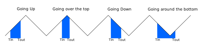

Many times when people analyse chorus, they assume that because the triangle wave has two slopes, rising and falling, there are therefore two situations (rising clock frequency and falling clock frequency). This is not true because the integration is done over a period and not at a single point. This gives us the four cases shown above.
Notice that since the area remains the same, tin and tout are closer together at the top of the waveform and further apart at the bottom. This is what you’d expect – higher clock frequencies give shorter delays, and lower clocks give longer delays, so the samples take longer to pass through. Effectively, the width of the blue block changes as it moves across the waveform, getting narrower as it moves to the top, and getting wider as it moves to the bottom. Try it out on the visualisation below by moving the tout slider:
This includes the three different clock modulation schemes we’ve just looked at, and lets you select either triangle, sine, or square waveforms for the LFO too.
Set the LFO waveform to Triangle and experiment with the different modulation types. Notice that the resulting delay time curve doesn’t look much like either the clock frequency or the LFO waveform, except for the Linear Period modulation case. Even in that case, the delay curve looks like a smoothed triangle, and the smoothing top and bottom and the two slopes are not equal.
That happens because the output frequency is faster at the top of the waveform than at the bottom. Change the LFO waveform to Square to see this effect more clearly. The delay time is constant for the flat sections of the clock frequency waveform, but the two slews caused by the rising and falling edges have quite different slopes. For the falling edge slew (from 50 to 75 msecs) the output frequency is low, so the slew takes longer to occur. For the rising edge slew (from 100 to 107 msecs) the output frequency is much higher so the slew is over quicker. Both slews take 512 clocks, but how long those 512 clocks take will vary!
How do we work out the pitch shift?
So far, we’ve been thinking about the delay time. However, for a musical chorus, it is probably better to think in terms of the pitch shift. Clearly we don’t want our modulation to produce a huge change in pitch – that would give us a woozy “seasick” chorus sound that no-one much likes.
To work out the pitch shift, we need to look at this in terms of sample rates. The signal is sampled at the input of the BBD, is clocked through the delay, and is then “unsampled” at the end. It should be obvious that if we read the sound out of the delay line twice as quickly as we read it in, the pitch will go up an octave. Likewise, if we read it out half as fast as it went in, the pitch drops by an octave. We can express this in terms of the sample rates like this:
pitch_shift = output_sample_rate / input_sample_rate
The output sample rate is simple since it’s just the current clock frequency, the rate now at time tout. Let’s call that fout. The input sample rate is whatever the clock frequency was 512 shifts ago, at time tin, so let’s call that fin.
pitch_shift = fout / fin
This pitch shift is a simple ratio, so to express it in more directly musical terms like octaves we need to take a log:
pitch_shift_octaves = log2(fout / fin)
We can turn octaves into semitones or cents by multiplying by a simple factor:
pitch_shift_semitones = 12 x log2(fout / fin)
pitch_shift_cents = 1200 x log2(fout / fin)
Note that what happens while the samples are being clocked through the delay doesn’t matter. They could speed up and then slow down again – we don’t care. That might affect the delay time, but it won’t affect the pitch shift. The only thing that makes any difference is the difference between the rate they went in and the rate they come out.
Looking back to what I said in the previous article, the rate of change of delay is not totally unconnected to this, since the delay is controlled by the clock rate / sample rate, and if it changes more, there is likely to be a bigger difference between the input and the output sample rates. So I was close, but I was wrong.
Since we’ve already seen in the previous section how we can find tin by using integration under the clock frequency graph, we have the information we need to plot the pitch shift. Here’s a visualisation with the Fout/Fin pitch shift relationship plotted:
As you can see, the pitch shift follows a complex shape. Linear Period modulation is the only way to get a simpler result. I’d never seen this effect dealt with seriously – in fact, most people seem to be completely unaware of it, and the only reference I found is in a paper by Antti Huovilainen for DAFX’05. This mentions the curving you get in the delay time, but it doesn’t look at the effect on pitch, and the graph showing the warping shows a relatively tame example and makes the effect look more manageable than it really is.
“As the delay line length is fixed, the delay time can be varied only by changing the clock rate.This is equivalent to changing the sample-rate with time and has two effects: First, if the clock rate is varied linearly, the delay time will be roughly proportional to 1/x. Second, as the clock-rate changes, the output sample-rate is not the same as the rate the audio was sampled in to the BBD. This causes some warping of the delay-time curve, especially if there are fast transitions or abrupt changes in the clock rate. Note that, unlike with digital delays, discontinuities in the modulating signal do not produce discontinuities in the delay time.”
Antti Huovilainen, Enhanced Digital Models for Analog Modulation Effects, Proc. of the 8th Int. Conference on Digital Audio Effects (DAFX-05), Madrid, Spain, September 20-22, 2005
Now, there’s some very interesting and non-intuitive results come out of playing with this visualisation. For example, notice that if you modulate the clock frequency with a square wave with two levels, the pitch shift jumps between three levels! Set the Mod Type to Linear Period to see this.
This happens because there can be three situations: the leading edge of the square, the level sections at the top or bottom, and the falling edge. On the leading edge, fout is already high but fin is still low. This gives an upwards pitch shift. Once tout has progressed far enough along the top of the waveform, fin is also high, so the two are equal and there’s no overall pitch shift. This same situation occurs most of the way along the bottom of the waveform. The other situation is the falling edge, where fout is low, but fin is still high. That gives a downwards pitch shift equal to the upwards one from earlier. So the pitch jumps between a raised pitch, no pitch change, a lowered pitch, and no pitch change – four steps, and three different pitches. That’s definitely a non-obvious result in my view!
Can we compensate for the distortions?
We’ve shown how the pitch shift doesn’t follow the LFO shape closely at all. We’ve also seen how, in the case of the delay time, we were able to change the modulation method to “pre-bend” the clock frequency curve to give a delay time result that more closely follows the LFO shape. Is something similar possible with the pitch shift? If we want a pure sinewave vibrato, can we pre-distort the LFO waveshape to give us that pitch shift?
It’s pretty clear from the maths that the answer is “No”, at least in general. We’d need an inverse function for our pitch shift function, and that is based on times tout and tin, and we find those using integration. In general there’s no closed-form solution for an inverse formula for integration.
The practical difficulties are real. The shape of the pitch shift doesn’t only change with LFO rate, but also with LFO depth and also with Clock Frequency. It also depends on the relationship between the LFO period and the delay time. With so many depedencies, the sort of techniques I would usually run for (“stick it all in a look-up table”) start to become ineffective, since the amount of memory required becomes prohibitive.
Note that the situation we’ve been looking at is where the integration period (the delay time) is short compared to the LFO period. This is typical for chorus, where the LFO period might be from 100msecs (10Hz) to 1sec(1Hz) but the integration period (and hence delay) is likely to be only 5 to 10msecs. Flangers push this further, often using delays of only a few msecs and LFO periods as long as 10secs. In order to get these short delays, flangers typically use much higher clock rates, and much bigger variation in clock rate (sometimes as much as 50:1 between the slowest and fastest, for maximum sweep!).
Incidentally, If the integration period happened to be the same as the LFO period, there’d be no overall pitch shift because the clock frequency at tin and tout would be the same. This would happen when the LFO period was exactly the same as the delay time. That’s unlikely with a 1024-stage BBD, but it’s possible in theory with a longer chip like a MN3005. In practice, this is analog electronics, and you’d never get the clock frequency and the LFO frequency to stay totally synced, so it’s a curiosity rather than something important.
Full-featured modulated BBD simulation
You can investigate some of these options with this full-featured modulated BBD simulation. I put it on its own page so you’ve got a bit more space. This lets you alter the LFO rate, depth and waveform, as well as allowing you to change the number of delay stages, the clock modulation type and plot either the delay time or the pitch shift.
Thoughts, comments, corrections?
Please feel free to get in touch or comment below. If you find anything wrong, let me know so I can fix it! Thanks!
Good work Tom.
Your article has inspired me to re-embark on the quest for the “Holy Grail” of modulation schemes; i.e. how to get the smoothest pitch variation under all conditions. Not easy I know, but there has to be an optimal solution for each combination of variables and with all the techniques we have available surely we can do better than a distorted triangle modulator.
As an aside, I had a play with with the final simulation and something doesn’t “feel” right to me; perhaps you can shed some light it. I set the output curve to Pitch and the Waveform to triangle and no matter how low the Depth is set (above zero) the actual pitch modulation is very different from what I’d expect – it seems to resemble a square wave at low levels. If I switch to sine it is markedly different and more how I’d expect it to be. If this is really what happens, why do pedal designs often use a triangular modulator without trying to convert it to a sine?
With short delays, the situation with triangle wave modulation becomes close to the simple theory where you only consider the slope up and the slope down, and ignore the parts going round the top and round the bottom. If the Mod Type is Linear Period, then the pitch shift for the two slopes is constant, so the output pitch shift looks like a square wave. This is the scheme used by Roland stuff like the Dimension D, with two delays fed with antiphase signals from a triangle LFO. As the delay gets longer, the slews caused by the integration period get longer and the distortion gets worse. You’ll see this on the sim – as you lower the clock frequency, for Linear Frequency, the flat top and bottom of the pitch shift square wave become more and more curved, and for Linear period, the slews get longer and longer.
I think you’re dead right that there’s a optimal solution for each combination of variables, but the trouble is that people often want controls on their chorus pedals (Rate and Depth at least!) and as soon as you start altering those, the goalposts move and your optimal solution isn’t optimal any more.
This is by far the most thorough investigation I’ve seen into the relationship between modulation waveform type vs BBD clock frequencies – for the first time ever this has been fully explained while taking all of the various factors into account. It is easy to read with only sufficient maths to explain the principles involved without becoming a research paper littered with complex formulas. The hands on visualisation tools that take us through the various scenarios make the effects of each individual parameter easily understood. The fully featured modulated BBD simulation is a work of art in it’s own right. Bravo Tom!
My idea is that the clock modulation waveform shape and magnitude would be determined by the delay time, modulation depth and frequency (and waveshape). If any setting is changed the clock modulation waveform changes accordingly to give the smoothest pitch modulation. Whether this can be done using conventional electronics or whether a microprocessor-based solution is needed, I don’t know…. Moreover, would any gains justify the effort and complexity?
Yes, I think that’s what it would take. And I think your final question is entirely pertinent!
I’ve just done a real-life knock-up of the modulated delay using an FX Core Evaluation Board, a signal generator an audio amplifier (and an oscilloscope). I can vary the modulation frequency, depth, and select between sine, triangle and square modulation waveforms. I can also vary the “static” delay time. I set it to output either the straight delay output or a 50:50 mix of dry and delayed signals.
And yes, the reality concurs with the simulations…I admit I had my doubts about triangle wave modulation producing a square-wave type pitch modulation because in all my years of playing with triangular-based modulation for such effects I had never really focussed on the unmixed delayed output, but there it is.
However, when you mix in the “dry” signal everything changes…. the pitch modulation is no longer apparent due to the more dominant (and still linear) phase-shifting producing time-varying nulls and and peaks in the signal and its harmonics. Even with a sine-wave audio signal, the amplitude modulation due to the comb-filtering is more dominant than any pitch-shifting… You never stop learning! Well done Tom.
How did you do the variable sample rate? Does the FXCore allow that sort of thing? Digital platforms are usually fixed sample rate (at least, these days they are – it wasn’t always so).
The sample rate is fixed but the architecture and assembly code allow for single instruction interpolation between samples (see Experimental Noize AN-1.pdf).
So my “knock-up” is using a circular-buffer digital delay with the read pointer position being modulated and interpolated over however many samples the depth is set to.
The digital architecture with fixed data sampling and variable position data reading are very different from the fixed number of stages and variable clock rate of the classic BBD line, but I believe “input-to-output” they do the same time warping function and certainly all the time related digital effects seem to behave like their analogue counterparts… I might be wrong of course.
I am going to knock up a simple frequency to voltage converter to “see” the pitch modulation vs time.
I stand corrected… I asked Google Chrome AI if a variable clock BBD delay and fixed sample-rate variable-pointer digital delay behave identically and the answer was un unequivocal “No”. This was supported by explanations and described the lag effect of the BBD propagation versus the immediacy of pointer changes.
This might explain why with my system, although I get square wave pitch changes using triangular modulation, it remains this way no matter how intense I apply the modulation. I can’t get the progressively more curvy responses with increasing modulation that your simulation shows.
There might even be another article in looking at how fixed and variable-rate sampling systems differ!
The biggest obvious difference is that the moving-pointer method can actually skip samples, whereas a variable-rate system like a BBD has to output every single sample in order. All you can do is change the speed that happens. That’s kind-of where the lag comes from, and what I think of as “blurring”. Rapid changes in the modulation get “smeared” across time.
Aware that this is deiviating from the article’s original scope a little, but it might be useful to someone…
An original tape delay system has a write head and read head positioned a short distance away. If you change the tape speed you change the delay time and this is analogous to a BBD delay. If you instead were able move the position of the read head w.r.t the write head you could also vary the delay and this is analogous to the fixed sample-rate digital delay.
With fixed sample-rate systems the pitch shift is simply the differential of the delay time modulating signal, hence the triangle wave modulation to square-wave pitch shift but, as you have shown, with the BBD variable sample-rate system the relationship is far more complex.
Excellent article Tom. Thanks for sharing!