
We’ve recently started stocking Alfa’s clone of the famous old Roland IR3109 filter chip. This is the chip that was inside a ton of Roland synths, including the SH-101, Jupiter 6 and Jupiter 8, Juno 6/60 and even the Juno 106, although in that case it was hidden in a potted module!
I thought it’d be good to have a look at some of these classic designs to see what we can learn about the chip and how to use it.
The basics – the datasheet filter
First let’s start with what the AS3109 datasheet gives us. It looks like this:
This basic filter circuit gives us the typical 4-pole 24dB/Oct synth filter, and this filter core shows up in a lot of the Roland designs without significant changes. There’s one big thing that’s missing though, and that’s resonance, because ‘3109 doesn’t include any on-chip control of resonance. The famous SSM2040 similarly didn’t have any on-chip resonance control, so this wasn’t unusual at the time.
Consequently, the differences in the filter circuits are mostly when you look at how the resonance is implemented. Since the resonance behaviour is quite a big part of the sound of an analogue synth filter, this is quite important so we’ll dig into that a bit. There’s also a couple of different takes on resonance compensation on show, so that’s worth a look too.
Juno 6
The Juno 6 has a fairly straightforward implementation. The filter part is the standard 4-stages with 68K resistors and 240p caps. There’s nothing especially special about the choice of 240p caps, and it is a bit of an unusual value (240p is an E24 value, rather than 220p which is an E6 value). I’d probably use 220p as a close-enough and much-easier-to-source alternative. 220p shifts the general range of the filter up a tiny bit, but since going from 240 to 220 is only about 9%, that’s not a big deal. Given that the CV can move the filter up or down over a fifteen octave range, we don’t care!

In the Juno 6 the resonance control is handled by one of Roland’s BA662 OTAs. The BA662 chip actually includes a buffer as well as the OTA but since the buffer isn’t used, we can replace it with the AS3080 OTA (Alfa do make a BA662 clone too, but it’s SMD-only and we don’t have any – by all means use it if you wish!). Notice that the Juno’s filter circuit includes resonance compensation to counteract the volume drop you get in the passband when you turn tthe resonance up. In this circuit, this is done in the “classic” way of increasing the input level to the filter to compensate. You can see that there are two paths to the resonance VCA, not just one: One comes from the filter output back to the VCA inverting input (marked “Resonance” on the schematic). The other comes from the input back to the VCA (marked “Resonance compensation” on the schematic). The effect of this is that as you increase the amount of resonance, you also add more input signal going to the filter input.
But hang on! Why is one signal inverted and the other not? Well, the filter stages produce 45 degrees of phase shift at the cutoff frequency, so after four stages, we have 4 x 45 = 180 degrees of phase shift at the cutoff. If we want our fed-back resonance signal to be in phase with the input (and we do, otherwise we won’t get any resonance!) then we need to invert it on its way there. Hence the signal from pin 15 goes to the OTA’s inverting input. The input signal however is already bound to be in phase since it hasn’t been filtered yet, so it can go directly to the OTA’s non-inverting input. The two inputs on the OTA come in very handy!
There’s one other feature of the OTA which is useful, and that’s the soft clipping that you get with increasing signal levels. This soft clipping acts to limit the amount of feedback that’s possible and keeps the filter from driving the output hard to the rails when it starts to oscillate. With no limiting at all in place, the supply rails would be the only constraint and the self-oscillating filter would produce a over-noisy square wave not a nice sine wave.
SH-101
The SH-101 uses a different approach to resonance compensation, although it’s still here. Instead of increasing the amount of input signal going to the filter to compensate for the volume drop, it increases the output level. I can’t think of another example of this approach off the top of my head.
The resonance circuit also shows what needs to be done when you don’t have a handy OTA with its two inputs available. The first transistor stage (TR2) is set up as a “phase splitter”, giving us inverted and non-inverted copies of the signal on its collector and emitter. We need the inverted signal to be fed back to the input as we’ve seen for the Juno 6 circuit. The non-inverted version is taken to the output so that it adds to the output signal when we increase the resonance. This effectively increases the VCA drive level rather than the filter input drive level like the Juno. I haven’t determined whether it starts to push the VCA into distortion, but it almost certainly does since OTAs aren’t the cleanest devices at the best of times. The question is really “how much?”.
TR3 is configured as an emitter follower, and notice that the original schematics don’t give a value for R19. Roland forgot to add it. OpenMusicLabs have checked the value against the PCB and it’s a 33K. Thanks to them for clearing that up!
The other part of the resonance feedback circuit which is interesting is the clipping diodes to ground. This fulfils the same purpose as the OTA clipping in the Juno and limit the level that the filter can reach when oscillating. Note that they don’t cause huge levels of distortion themselves because they reduce the level as soon as they start to conduct. Furthermore, the small level of distortion they do produce is fed back to the input, so it is heavily filtered before you hear it. This gives the sound “character” without it being offensively gritty.
There’s another thing that’s unusual about the SH-101 – its power supply. It could be powered from batteries so you could add the optional modulation grip and bounce round the stage like a….gulp! GUITARIST! It has a frankly ridiculous number of different voltages available internally, including +15v, +14V, +9V, and +5V. The IR3109 is powered in a single-supply style from 9V and Ground, with the 5V rail acting as a midpoint (ish!) “virtual ground”.
If you were cloning it, you could probably simplify the power a bit.

Jupiter 8
Here’s the filter from the mighty Jupiter 8! As you can see, the slightly-later Juno 6 above uses basically the same design, except without the option of a 12dB output.
There’s a note in Electrical Characteristics of the Alfa AS3109 datasheet about the buffers on the chip. Stages 1 and 3 have buffers that can supply up to 0.6mA, and stages 2 and 4 have improved buffers (1mA and 1.3mA respectively). Notice that the Jupiter takes the output from stages 2 and 4, the better buffers. Trying to tap signals directly from the lighter-weight buffers at stages 1 and 3 might not work the same way. At least, it’s something to be aware of.
 I haven’t done much more than sketch the outline of the CV mixing, because it’s all rather specific to the details of the Jupiter’s voice circuit. It’s just a basic inverting op-amp mixer circuit, anyway. There’s a voltage divider on the output of the mixer to reduce the level for the chip, and it uses a temperature compensation resistor, although that’s probably not doing a great deal.

Jupiter 6
Now, this is the most unusal filter Roland ever designed around this chip. It uses a dual state variable filter (SVF) structure, where both separate filters share the same control voltage. They have to, because they’re both using the same 3109 chip.
Another whole 3109 is used for just two OTAs to control the resonance in each stage. It looks like Roland didn’t have a dual version of the BA662 handy!
Again, notice the arrangement of the stages. Roland have used the stages with the better buffers for the first integrator (Integrator A) in each filter, and (in the other 3109 chip) for the resonance VCAs too. Again, we don’t know for sure whether changing this around would work the same way – because the buffers are different, it would be a significant change.


Boss PH-2 Super Phaser
Here’s something a bit different! This excellent phaser uses two IR3109 chips to provide 8 swept phase shift stages. It adds further standard op-amp-based fixed phase shift stages to that for a grand total of 12-stages. Using the IR3109 enables Boss to squeeze a lot of phaser into a compact enclosure. Nonetheless, the circuit has a lot of parts. Here’s the whole thing:
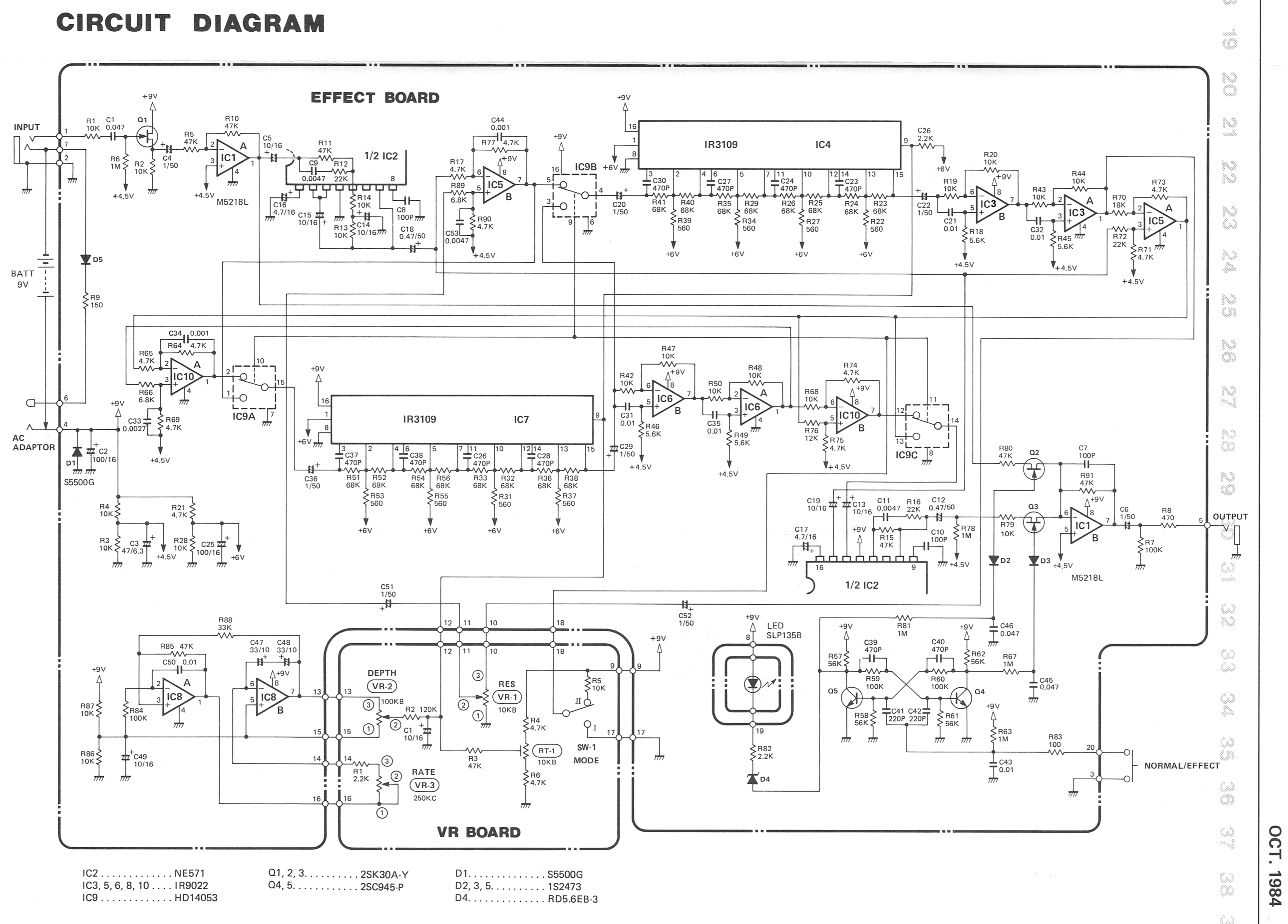
The pedal has two different modes which reroute the different stages using IC9, a 4053 triple CMOS switch. Mode 1 is a 10-stage phaser with global feedback around the whole thing to provide resonance. Mode 2 is a 12-stage phaser, but it is constructed as two separate 6-stage phasers in series. The Resonance control alters only the resonance of the first phaser block. The second block is set up with a fixed resonance that you can’t turn off. Here’s a block diagram of the two different routings:
 Notice that both the resonance mixers and the phase mixers are implemented as differential amplifiers. This enables Boss to account for signal inversions and still get the mixing effect they’re after.
For the purposes of looking at the ‘3109 chip, I’m mostly interested in the implementation of the allpass stages. Here’s how that’s done in the PH-2. As is often the way, an Allpass filter is a mixture of a Lowpass and a Highpass stage.

Boss included a little RC filter on the CV input. This is set at 0.1Hz, so it affects the majority of the LFO speeds (the LFO range is from 0.071Hz/14secs to 10Hz/100msecs). This means that the very slowest sweeps are a full amplitude triangle, but as you turn the rate up, the LFO waveform will become more and more like a sinewave and the amplitude will drop because of the filtering. This has the effect of automatically reducing the sweep width with increasing speed. This is a trick you sometimes also see on chorus pedals.
The final thing to say is that Boss wrapped a 571 compander around the whole phaser circuit to help keep noise down. That’s probably a very wise idea. OTAs don’t have a great Signal/Noise ratio because the signal levels are so low, and the IR3109 chip is four OTAs in a row, and this circuit uses two IR3109’s in series, so there’s plenty of opportunity for noise to build up!
Conclusion
I hope you’ve enjoyed this review of the various ways Roland used the IR3109 chip, and I hope it inspires you to try your own designs with the AS3109. Personally, I think I can definitely see a few 3109 projects on the horizon!
Pop over the the shop to grab a few of the AS3109 chips and get your DIY on!
References and Resources
Here’s the original sources for what I’ve summarised above:
- AS3109 Datasheet
- Roland Juno 6 Service Manual
- Roland SH-101 Service Manual
- OpenMusicLabs Corrected SH-101 schematic
- Boss PH-2 Super Phaser schematic
- Florian Anwander’s excellent history of all the Roland filters
- AMS Synths page about the IR3109 chip. This includes a lot of very useful technical details which there’s no point me repeating here.
Feedback and comments
Any feedback is appreciated! Please comment below.
Bought a couple of 3109’s a while ago along with some other chips and when I had built the others I have just now gotten to the 3109’s so the timing of your article is excellent! Will take a go at the 101 filter. Thanks for taking your time to write this.
Thanks Ben. I’ll try and get to those Jupiter filters soon too!
I have been trying to set this up with varying results and I think there is an issue in the SH-101 compared to the original schematic. In this schematic R8-11 goes to the virtual ground at +5V while C1-4 goes to ground.
Looking at the SH-101 schematic and also the MC-202 all those components goes to the virtual ground at +5V and share their reference voltage, just like in the data sheet for the AS3109 where they connect at ground.
Hi Ben, Thanks for the pointer. I’ll have a check tomorrow.
Update: Now corrected in the article, Rev.2 SH101 schematic uploaded.
Tom
Great info! Thank you. I did a bit of research and the ERSB33G561 on the Jupiter 8 CV section looks to be a 560 Ohm 3300ppm tempco.
Thanks Matt, very interesting!