Description
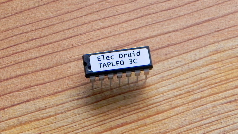
The TAPLFO chip adds a powerful feature to your LFOs: you can set the LFO frequency by tapping a tempo on a button connected to the chip, or by changing the Tempo CV. With this chip you can build tap tempo effects units or stompboxes, tap tempo controlled drum machines or tap tempo sequencer clocks. All of these are described in the datasheet below.
The LFO can produce 16 waveforms in two sets of eight, including a random (sample & hold) wave. All the waveforms except the random wave can be altered by the wave distortion CV.
The chip also includes a tempo multiplier. This is combined with the tapped tempo to allow the LFO frequency to be set at a multiple of the tapped rate. The available multipliers are 0.5, 1, 1.5, 2, 3, and 4. This allows half- and double-time, and triplet times.
The LFO tempo, multiplier, waveform selection, wave distortion, and output level are all voltage-controlled using 0-5V.
Download Electric Druid TAPLFO3D tap tempo LFO Datasheet
The datasheet includes example circuit diagrams, example waveforms, and the chip pinout diagram.
If you’d like to program your own chip for personal use, code and further details are available over on the original article about the new Druid chips.
January 2023 – New version 3D!
It turned out that in certain circumstances, the Clock Output on the 3C chip dropped output pulses when used with a stream of sync input pulses. The new 3D version fixes this minor bug.


simscia (verified owner) –
Swapping (with minor mods) a taplfo2d for the taplfo3 in a tap tempo tremolo pedal i solved issues with ticking and tap. A lot of waveforms fidelity has been gained too (this was not an issue for me anyway). Great step forward anyway
Laurent MOREAU (verified owner) –
I made 2 different PCBs for this project for my modular synth, one with full features, and another one quite simple, but I can’t get one of them working (none of the 3 ic versions A,B,C)… Warform selector is unpredictable or do nothing (depend on the age of the capitain i guess); same thing with a pot. Waveform set one gives a sort of fixed voltage (vary with the frequency pot), and so on… I check my boards millions of times and i’m sure both fits the schematics . Maybe i’ve done something bad, but i can’t find what it is… Sad.
I have a vcdo too, waiting for construction, but…
I do diy for a few years now, and i never faced such a fail…
Tom Wiltshire –
Email me and we’ll discuss it. Don’t worry, it’s probably something simple. Can I have a look at the schematic you used to design the PCBs from? There may be something there you haven’t spotted.
Tom
MOREAU Laurent (verified owner) –
Finaly it works!!! That was my fault (bad board cleaning…), so really take care of it.
Tom Wiltshire –
Glad to hear you got it running, Laurent. Enjoy the LFO now it’s going!
Michael Van Dijck (verified owner) –
Great stuff! Very well documented so it’s a breeze to implement it in your designs. Dirt cheap too if you consider the hours that must have gone into development. Add to that the speedy delivery and you get another happy customer.
iain Moore –
Have one of these running on the gain channel of a parametric EQ – loving the effect.
One quick question – is it just a case of pulling pin 2 the gnd to invert the waveform, or is there something extra I have to do?
Tom Wiltshire –
Hi Iain,
No, pulling pin 2 low inverts the behaviour of the CV inputs, not the waveform output. If you pull pin 2 low, all your controls will work back-to-front! This is actually quite useful if you want to put a CV mixer in front of the inputs, since the typical op-amp mixer is inverting.
To invert the output, either just use a x1 gain inverting op-amp, or invert the 0-5V PWM signal using a NOT gate or some equivalent before you filter it. This is a nice trick because at that point the signal is still digital, so you can do stuff like that!
iain Moore –
Brilliant, many thanks for the info Tom 🙂
Gary Kalar –
great IC, saves a ton of room, syncable, lots of control, and cheap, perfect! the “stomplfo” 8 pin is a great addition to the family too, bravo
STARON ELEKTRA (verified owner) –
Great and usefull chip! Honesty and great contact. When something went wrong with the previous version of the chip I just got a new one without making a complaint! Thanks Tom.
Jaga (verified owner) –
Love this. So many cool effects such as tremolo, vibrato, phasers etc. could sound better with this LFO chip.
I’m curious if someone added an option to switch between two speed settings (fast and slow) so that the speed change would happen gradually, not instantly (kinda like on a Leslie speaker). There’s a well-known LERA circuit on geofex, but I’m not sure it can be adapted to 10K pots.
Tom Wiltshire –
Slow ramping between rates would be possible by filtering the control voltage from the pot. If you did that with a passive filter, it’ll interact with the pot, so it might work better with an active filter.
Miquel –
I love these LFO’s, and I’ve used lots of them in several projects. However, it’s my first time with this version 3, and I’m a little confused with the CV Invert pin. I plan to use it with the inversion on, like the schematic. But I want to use a switch for the Level CV (for panel space reasons). The idea is turn the level off when I’m using modulation and put it to max when I’m not. I’m using the same inverting mixer like in the schematic (I’m using the attenuator for cv input, but I don’t need the level pot), and it’s just a matter of substituting the Level pot for a switch. But if I do that, according to the schematic (with the inversion active), max level would be ground and the minimum level would be -5v. Is this correct? I just want to be sure. Thanks in advance.
Tom Wiltshire –
Not quite correct. The CV Invert swaps the way around that the CV works, but the CV remains 0-5V. With the CV inverted, 0V is max, 5V is min. So for your switch for the level, you can just ground the input to get maximum level. For the other ‘modulation’ position, the right voltage depends on what type of modulation you’re applying. If it’s a unipolar signal like an envelope, you need 5V. If it’s bipolar like an LFO, 2.5V would be better (gives you room to go both up and down in level). HTH!
Mariano –
Hello Tom, I’m trying to get my head around the distortCV, im working on a phaser and when the pot its at its max and its lowest position the phaser goes away, the easiest way is to limit the pot travel with resistors but ive dug your code to the part where says PhasedistortionCV and trying to undestand its parts, i’ve searched in the datasheet but it gets more confusing, so far ive figured out the bits for ad5 but cant wrap my head on how to limit the range to 35% – 65% @ 0.625V and 65% – 35% @ 4.375V.
Id like if possible for you to point me to the right direction?
Thanks! 😀
Tom Wiltshire –
So you want phase distortion from 35% to 65%? Only 30% of the travel around the centre point? Is that right?
You’ve already spotted that the simplest way is the non-firmware solution of just adding resistors to the top and bottom of the pot. However if you want a firmware solution, you need to mess with this routine:
; Update the Phase Distortion CVPhaseDistortionCV:
movlw b'00010101' ; AN5, ADC On
call DoADConversion
; Limit the range of the DISTORT_CV to 16->240
movwf TEMP
lsrf TEMP, f
lsrf TEMP, f
lsrf TEMP, w ; Get top 5 bits of value in W (0-31)
subwf ADC_VALUE, w ; Subtract W from ADC_VALUE (gives 0->224)
addlw D'16' ; Shift values up 16->240
movwf DISTORT_CV ; Store the phase distortion value
; Update the frequency increments then return to mainloop
goto UpdateFreqIncs
This already limits the extreme ends of the range to prevent calculation errors from arising, but the method that is used doesn’t lend itself to being extended to your purpose.
The way I would approach it is to take the ADC value (which is in W and the ADC_VALUE variable after the DoADConversion subroutine) and multiply it by 30%. For an 8-bit number, that’s about 76. Then you need to add an offset of 35% on to the result. Again, for a 8-bit number that’s about 89.
That gives you a final output of 89 to 165.
However, that needs full 8x8bit multiplication. A quicker, cheaper, easier way is to simply downshift the ADC value by a couple of places so that it has a 0-63 range instead of 0-255. That’s 25% not 30%, but it’s close. Then add on your offset to centre that range around the 50% mark, so we add 96.
; Update the Phase Distortion CVPhaseDistortionCV:
movlw b'00010101' ; AN5, ADC On
call DoADConversion
; Limit the range of the DISTORT_CV to 96->160
lsrf ADC_VALUE, f
lsrf ADC_VALUE, f ; Shift down to 0-63 range
movf ADC_VALUE, w
addlw D'96' ; Shift values up 96->160
movwf DISTORT_CV ; Store the phase distortion value
; Update the frequency increments then return to mainloop
goto UpdateFreqIncs
Mariano –
Thanks a lot Tom, works flawlessly. 😀
Mariano –
Hello Tom it’s me again
Ive been digging your code and can’t get to locate where the LFO range is generated, what i want to do is set a minimun of 1Hz and a maximum of 25Hz, also is there a way to mantain same LFO range no matter the tempo multiplication?
Thanks! 😀
Tom Wiltshire –
The LFO range is generated by the “FreqIncTable” lookup table at the end of the code. This table is used by the TempoCV routine to convert the 8-bit control knob position to a frequency increment used by the LFO.
I don’t really understand what you mean by “mantain same LFO range no matter the tempo multiplication”. Do you want to disable the tempo multiplication?
The simplest way to limit the range is in hardware. Add a resistor below the Tempo pot to increase the minimum frequency. Tie the Multiply CV to a fixed voltage to disable it.
Mariano –
Hello Tom thanks for the reply
Im not sure how to explain this cuz english is not my main language 😛
when on multiplier x1, the overall range of the lfo when using TempoCV is lets say 0.5Hz on 0v and 10Hz on 5v
when on multiplier x2, the overall range of the lfo when using TempoCV is 1Hz on 0v and 20Hz on 5v
and so on,
whay im after is to mantain the same overall range of the lfo when using TempoCV
for example
when on multimplier x1 the lfo range with TempoCV be 1Hz at 0v and 20Hz on 5v
when on multiplier x2 the lfo range with TempoCV be 1Hz at 0v and 20Hz on 5v
dont know if that makes sense when readed as it it does in my head haha
Regards.
Tom Wiltshire –
So what you’re wanting is for the Multiplier CV to simply not do anything – Just set the Multiplier CV to x2 with a trimmer and never touch it again! This gives the chip a range from 0.1Hz to 25Hz. You can then limit the range to the part you need by adding resistors above and below the Tempo pot to adjust the voltage divider.
Mariano –
Hello Tom
Hope this explains better
Let’s say that when I’m using TempoCV pot the range of the lfo is 1Hz to 20Hz; once I use tap tempo, the range of the lfo together with MultuplierCV works as intended, once I go back to using TempoCV pot again the range of the lfo is 1Hz to 20Hz, as if it had two different ranges, one for tapped tempo and one for TempoCV.
Thanks!
Tom Wiltshire –
Ok, so you basically want to disable the Multiplier for the TempoCV pot. That’s not impossible, but it’s not immediately obvious either! Drop me an email and we’ll talk about it more.
Ben –
Hi Tom, I’m currently planning a module that combines this chip with the One Shot Event Generator and a stomp LFO chip. I was just looking at the modular schematic for this chip and wondered if it would be possible to have both the bipolar output and to take a tap after the filter op amp stage to get a 0-5V output. Looks like the signal would be inverted at that point so I would need another op amp to flip the signal and get 0-5V, right?
Tom Wiltshire –
Yes, that would work. The problem would be that one output would have less filtering than the other. If you’re going to add one op-amp stage to the circuit, it might be better instead to remove the Zero Adjust offset from the second filter (just tie that pin to ground). That filter will then give you a 0-10V unipolar output. You can then add another op-amp stage to add the offset and derive a bipolar +/-5V signal.
Ben (verified owner) –
Thanks Tom! So that final op amp stage would be something like a 100k resistor running into the inverting input another 100k resistor running between inverting input and output with offset on the positive input, right and a final resistor running from op amp out to output jack, right? Or would I need a capacitor in there somewhere?
Tom Wiltshire –
No, that sounds like it would do it. The cap would only be necessary if you are worrying about noise or op-amp oscillations.
junk mcnuggets (verified owner) –
just wanted to say i dearly love the TAPLFO3 and this entire site/company. i was just reading through thr comments and realized this cat answered every single dude’s questions until they absolutely had a working circuit that they were after. just f@#%ing bravo, man. that is amazing. i love this place. And thank you, dude.
Ben (verified owner) –
Hi Tom, just getting back to my build. I’m almost done but was just looking at the full CV control over the waveform selector that is part of the modular synth schematic. I want to just make this a simple pot control like the circuit that runs into the multiplier CV. Was just wondering whether I need +5V or -5V on the pot if I do it this way.
Tom Wiltshire –
The modular synth schematic has pin 2 grounded, so the CVs are inverted. That means that Max is 0V and Min is +5V, so connect the pot like that. HTH.
Ben (verified owner) –
Finally got around to building my module with this chip and the ONESHOT. Really great chip. I built the module with CV control over Frequency, Wave Distort and Level. I’m a little on the fence on the value of modulating the Wave Distort with CV. Will have to play more to see if I can find some interesting possibilities there. The CV invert function is nice in saving op amp stages for the inputs.
Luis –
Hello Tom
Is there a way to make square wave more like a trapezoid?
I’ve looked in the pulse generation routine but makes no sense to me 🙁
Tom Wiltshire –
There’s not a simple way, no. The Wave Smoothing feature does that to an extent, but it’s most notable at the highest frequencies (since it’s just a basic filtering action).
It would be possible to add a variable slope to the square waves, but it’d be a whole different thing. A square-to-triangle waveform with a CV to control the degree of each would be a good thing to play with…maybe on a future project?!?
Stephan (verified owner) –
Hiya, great chip so far and easy to use. I was wondering how the tap input and frequency CV interact. Can I use both, where whatever got touched last determines the frequency?
Tom Wiltshire –
Yes, you can use both. Whichever you adjusted most recently is what gets used, like you suspected. If you tap, you get the tapped tempo. If you then tweak the frequency knob, you get the frequency given by the knob. It’s pretty straightforward.
garyrolfe1 (verified owner) –
Hi Tom. I’m looking at the suggested circuit for converting the cv inputs for use with bipolar Eurorack voltages. If I accidentally exceed the + and – 5 volt limit, will the chip be damaged? Thanks
Gary
Tom Wiltshire –
Make sure you have a series resistor between the external input and the chip’s CV input pin. 2K2 to 4K7 is a good range. This protects the internal diode from too much current, and should keep the chip safe.
Miquel (verified owner) –
Hi Tom, I need for my project a 0-5v output. What would be the easiest way to achieve that? I imagine I can use the simple passive filter you show in the data sheet and add a simple voltage follower after it. Would that work? Thanks
Tom Wiltshire –
Yes, that’d do it! You’ll lose a little bit of voltage with the passive filtering, so you might find you finish up with 0V to 4.5V instead. If you really need an accurate 0-5V, you can add adjustable gain to the op-amp. Mostly it doesn’t matter, and it just limits the maximum depth a tiny bit.
Marcel Wiegers (verified owner) –
I spent some time figuring out why 2 TapLFO’s with some shared potmeter CV’s make the chips behave weird. I have a project running 2 TapLFO’s, one receives midi clock from A PIC with Tom’s midi clock code and the second receives clock from the first TapLFO. I’m controlling some CV’s, like division and waveform, with the same pot for both TapLFO chips but I was getting weird behaviour, the tempo went crazy at random times. Using a 10K resistor for each chip from the middle lug of the pots did the trick. Maybe obvious for the most but I thought it was worth mentioning.
Tom Wiltshire –
Thanks Marcel!