
Here’s something slightly different! Is it an LFO? Is it an envelope generator? Well, it’s a bit of both. It produces a one-off event like an envelope generator, but it has a selection of waves more like an LFO.
It works by producing a single “ping” when triggered. A ping is like a mini-envelope. The rate and waveshape of that ping are variable (from 55 msecs to 2.5 seconds, and eight different shapes), and the single ping can be augmented by adding “echoes” which die away linearly. There are controls for the delay (from 0 to 2.2 seconds) and the number of repeats (from 1 to 36) for the echoes.
Rather than explain it a lot, here’s some example outputs to give you an idea:

Note that depending on the Rate CV and the Delay CV, these shapes could take a few hundred milliseconds or over ten seconds. The longest event the chip can produce takes over two minutes to complete, and the shortest is over in 55 msecs!
The chip is a simple 8-pin design based on the StompLFO chip and codebase.

Like the StompLFO, it uses Pulse Density Modulation (PDM) instead of Pulse Width Modulation (PWM) for the output. This enables the output frequency to be much higher (2MHz instead of 10’s of KHz) and that means simple RC filters can smooth the output easily without losing any waveform detail.
The eight different ping shapes look like this:

The Sine shape makes sounds like a ball being dropped on the floor (BOINGBoingBoingboingboing!), whereas the Cosine is smoother and makes a more “FlubFlubFlubflub!” sound. The spiky Log curves can be used as simple percussive envelopes, good for drums and hits, and you can add echoes for emphasis. The Ramps can produce noises reminiscent of scraping a washboard. And the inverse sine is just weird!
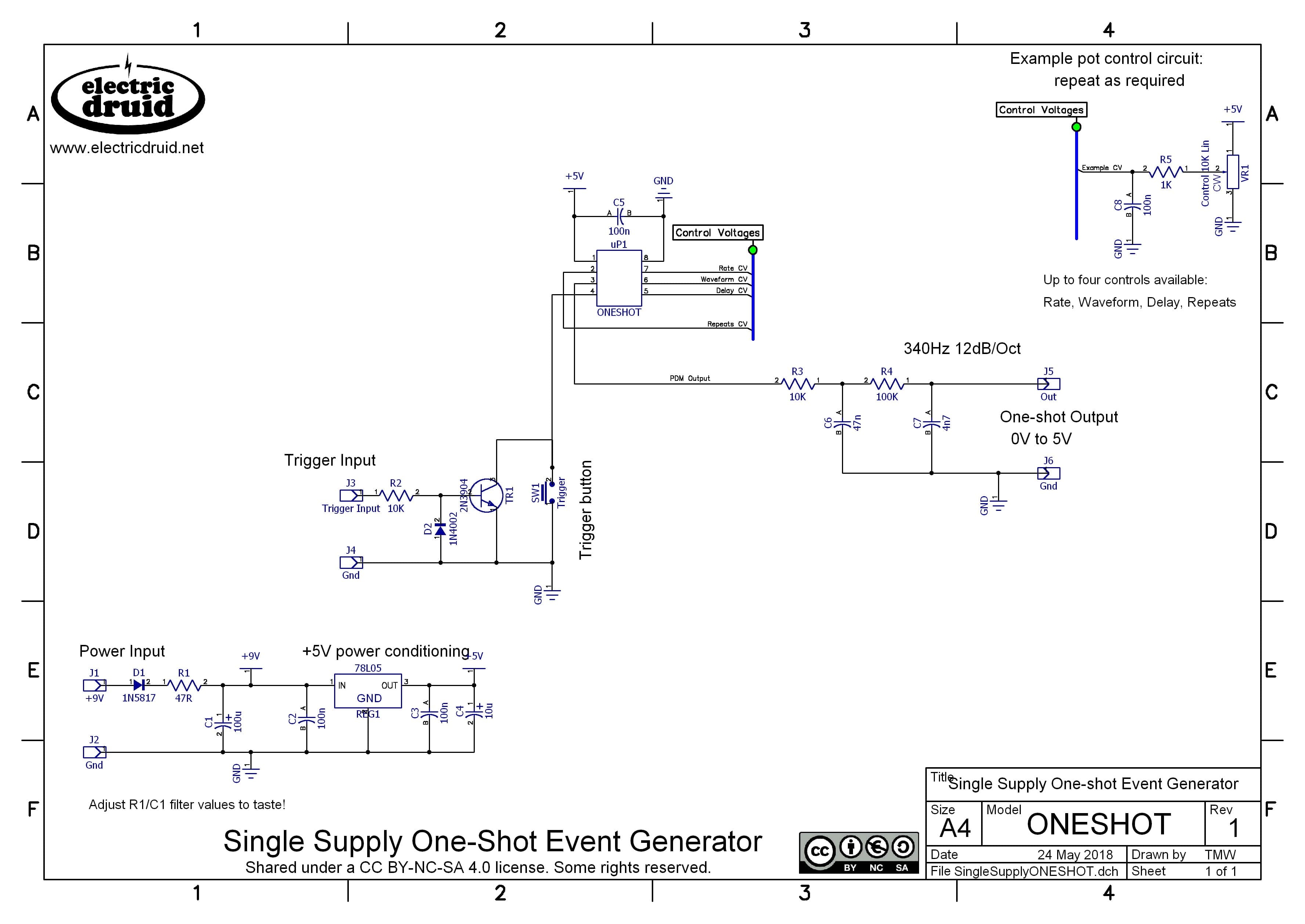
The circuit is very simple. Here’s an example running from a 9V stompbox supply. Since the circuit only needs a 5V supply, you could easily run this from 12V in a eurorack system, or 15V in a full-size modular (but mind the regulator doesn’t get too warm if you drop 10V across it).
Thanks
This project was developed as the result of an email conversation with Mark Hammer. The original idea is entirely his, and the final version is pretty close to his initial concept, although practicalities meant that it finished up only producing unipolar waveforms. We discussed bipolar shapes too, and had various ideas for that, but I decided that would have to be a different chip. I’m grateful to Mark for sharing his idea and letting me implement it and present it here.
ONESHOT details
- One-shot event generator PIC 16F18313 ONESHOT.ASM code
- Assembled ONESHOT.HEX code from above file
- ONESHOT 8-pin event generator Circuit Diagram
- ONESHOT datasheet (includes circuit diagram and chip pinout)
If you can’t program your own chip or find a friend to program one for you, we have OneShot chips in the shop.
As ever, any feedback or comments about the chip or the things you find to do with it are appreciated. Please send us an email. Thanks!

OneShot by Tom Wiltshire for Electric Druid is licensed under a Creative Commons Attribution-NonCommercial-ShareAlike 4.0 International License. Here’s the legal stuff.
Great to see some fresh ideas! I already captured the schematic, this could make for a nicely integrated eurorack module.
Do the inputs have sufficient sampling rate for cv controlling with an LFO?
Waiting to hear from you regarding “help wanted”.. 😉
All the best!
I would really like to see a preprogrammed chip with this function, I think it’s a great and original idea.
Love the site in general lots of interesting and useful info.
would love to have a preprogrammed version!!!!! please please make it!
Hey, we just built built a version of your One Shot circuit. When looking at the output on an oscilloscope we get a 0-5V range. However as soon as we plug into any input, the output level is severely diminished, @ 0-0.5V. Maybe it’s an output impedance issue? We tried going through a buffer and some different output resister values, but nothing seemes to fix it. Any ideas what could be the cause?
It sounds like the output is getting loaded down. With the passive filter, that’s not unlikely, but I’m surprised your buffer didn’t fix it. What did you use?
If you’re still having trouble, you could also try using one of the active filters from the StompLFO or TAPLFO datasheets.
Hi!
i had the same issue with too low output. I could solve it with a bufferd/active filter. I used a LM358 with +12V from my eurorack-powersuply. I can’t say if it also works with +5V. I guess it should.
For information on how to turn a passive filter into an active i recomend this video by Moritz Klein. I recomend any of his videos: https://www.youtube.com/watch?v=YNoj9Rrw_VM
Only thing that made me wonder was that, when i put a 10k resistor at the output of the last buffer (wich some people recomend to protect the op-amp) the voltage was cut at +2.5V. the reason could have been, that i also put a signal LED at the same output with 100R protection. Maybe there was some strange voltage-divider happening. with 100R it’s too bright anyway. so i removed the 10k (because other people say it’s not necessary with modern op-amps). Put a 1k before the LED. maybe it is still too bright.
i like the effect of this chip a lot. Thanks for creating it.
If you’ve got 10K in series with the output, I’m not surprised the level dropped. You need to consider the *input impedance* of whatever you’re feeding. 1K is more typical to protect the op-amp, and into a 100K input impedance, this won’t cause a significant voltage drop, unless you’re talking about Pitch CVs. For modulation sources, it’s fine.
In the case of the passive filter, R3 and R4 are essentially in series with the output, so you have an enormous 110K output impedance. That’ll cause noticeable losses into all but the largest input impedances (~10% into 1M, for example). An active filter can avoid this problem and drive much lower input impedances/heavier loads.
As I understand from the schematics the CV-inputs are non-inverted.
Do you have a example on how to use CV-inputs as well as pots for the non-inverting inputs? Every example I can find (in the datasheets of your other ICs) seem to use inverting inputs.
Cheers!
Great little chip and schematic! I bread boarded and then created a DIY circuit on 5x7cm perf board. Worked perfectly first time following the given schematic. No issues with the passive filters. The output signal from the board on my oscilloscope was clean, smooth, ranged from 0v to a full 5V and followed all the shapes on the chip. I did not have the same diodes in my parts box as in the schematic but used 1N4007 instead which seems to work just fine. I even added another 2N3904 transistor off the trigger input to drive a LED which lights up when an input trigger is received. Can’t have too many LEDs on your DIY Synth! 🙂
Thank you very much for sharing this idea & schematics! I’ve got a noob question: is the VR1 in area AB4 (CV input) a vactrol or what does VR stand for?
Thx & best regards,
Michael
No, VR1 is a variable resistor, a potentiometer. It’s wired with one end to 5V, one end to ground, and the wiper than provides a 0-5V CV to control the chip. Since there are four CV inputs on the chip, you need four pots like this.
Note the 1K/100n filters are “best practice” only – they’re not essential and if you want to simplify it, you can leave them out.
HTH!