
Replacing the LM3914/LM3915/LM3916 with a PIC
Most designs you see for audio level LED bargraph displays use the LM3914/LM3915/LM3916 series chips that are no longer made. However, the chips are simple, so we can replace them with a PIC and build a nice LED bargraph driver on a single chip.
So why do you need this thing?
You need this if you want to display an audio level and make sure it doesn’t go above some well-defined threshold, usually the level at which clipping occurs.
My personal situation was that I’ve been working on project that has a variable overdrive circuit, followed by a level control. This is then followed by some other circuits, like a reverb, and I’d like to avoid the drive circuit causing clipping in the following stages, which is possible if you turn both the Drive and the Level up at once. It occurred to me that I needed a simple audio meter circuit, one of those little LED bargraphs that show you how loud things are. Putting such a thing between the overdrive stage and the rest would enable me to see easily when the level was good for the next stage, and help me balance clean and overdriven sounds. Furthermore, more blinky lights is better, right?!
Most of the designs you see for such things use the LM3914/LM3915/LM3916 series chips by National Semiconductor. NatSemi were bought out by Texas Instruments in 2011 and the LM391x chips are no longer produced. There’s still few around, but it didn’t seem like a bright idea for a new circuit to use a discontinued chip. The chip itself is very simple though, so I thought it’d make a quick PIC project. This page describes that project.
How do the LM3914/LM3915/LM3916 chips work?
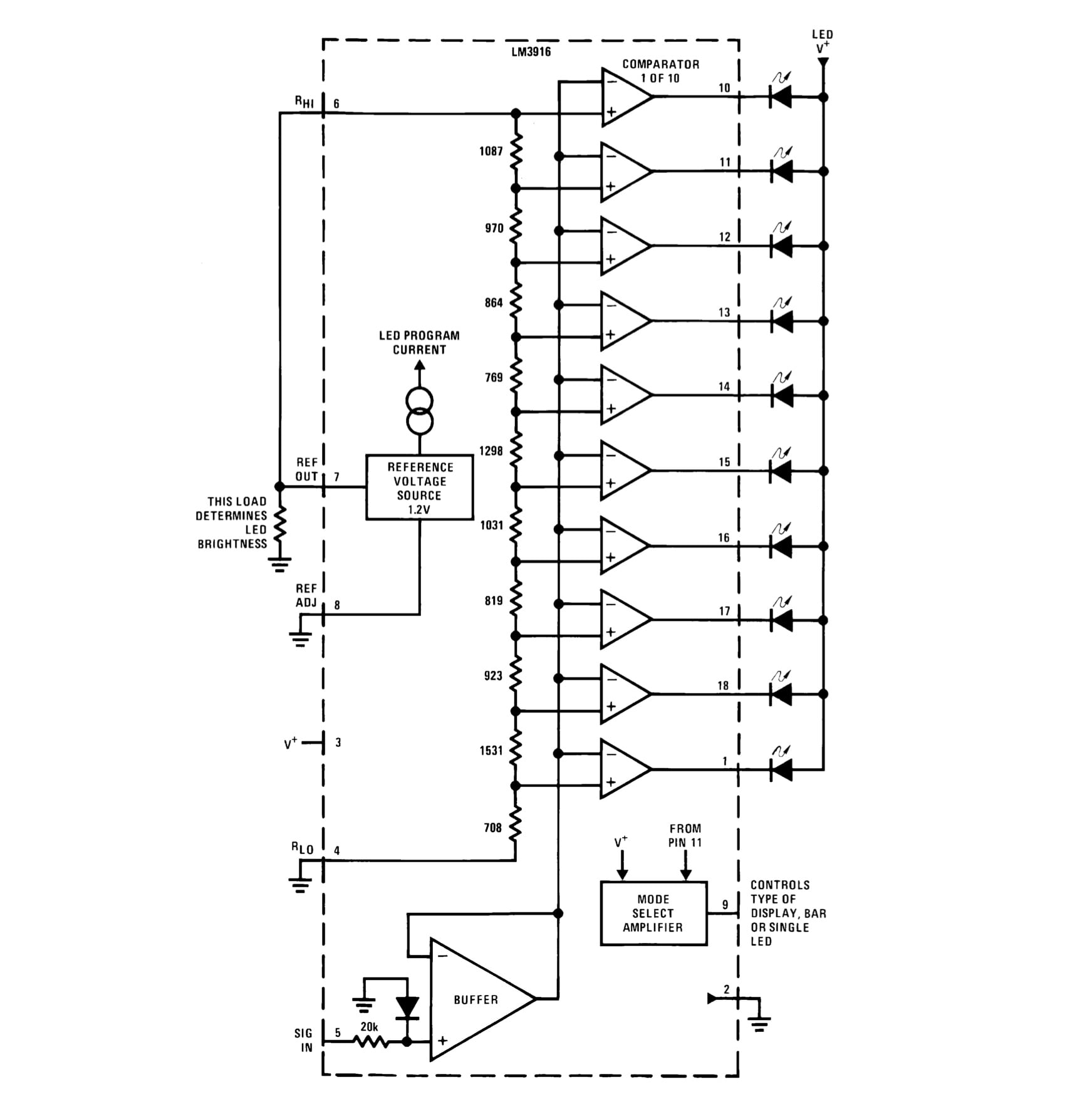
So…what do the original chips do? They’re basically all the same, consisting of a resistor string creating threshold voltages which are fed to comparators that compare the given threshold to the input. The comparator outputs drive individual LEDs. The chips contain ten comparators and thus drive ten LEDs. The only difference between them is the values used in the resistor string: LM3914 is linear, LM3915 has 3dB log steps, and LM3916 is set up with the typical steps for a VU meter. There’s a good YouTube video that compares the responses of the three chips. Which do you like best?
There’s also current limiting on the chip, which means you can connect the LEDs directly without needing a series resistor. We’re not going to be able to do that unfortunately, but a few resistors isn’t a big deal.
PIC-based LED bargraph driver: hardware design/schematic
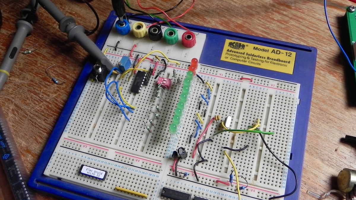
My first step for this project was to sketch out the schematic above.
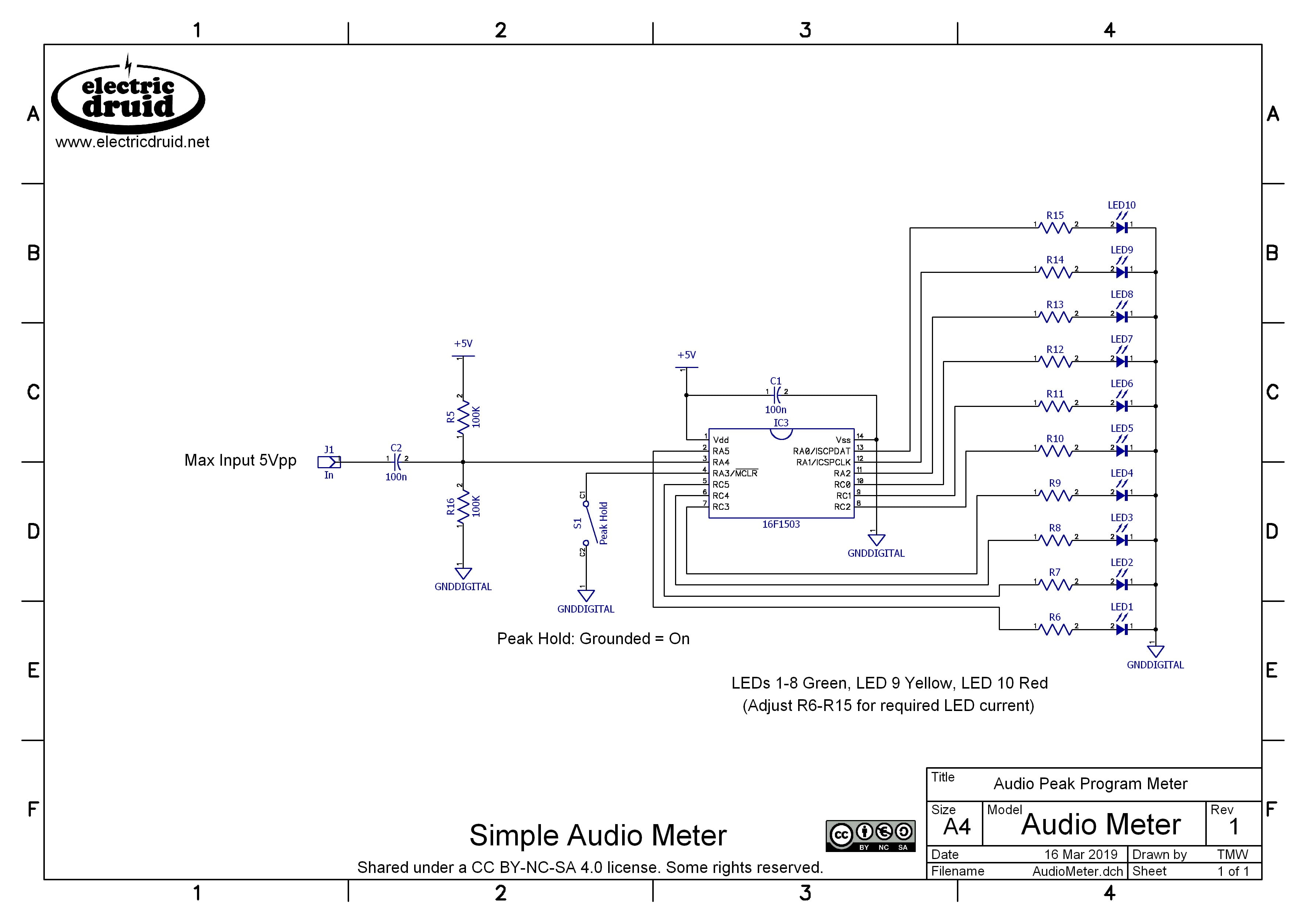
This was pretty straightforward. I needed 10 output pins and 1 input pin, so that’s 11 IOs. Adding a couple of power pins makes 13 pins, so a 14-pin chip like the 16F1503 was going to be the smallest device that would do the job. Since RA3 is input-only, it would have to be the “extra” pin, and I sketched a switch connected to it for some option (the original Nat Semi chips had a “bar mode” and “dot mode” that you could select between). Audio is AC-coupled via a small capacitor to an ADC input held at a midpoint voltage by a simple voltage divider. This is the same scheme I used on the DigiDelay, so I know it works. The LEDs I had around have Vf of 2.1V and 2.2V, which gives a resistor value around 1.45K for 2mA current. You can check this on this useful LED series resistor calculator if you like. In the end, I used 1K2 for all the LED resistors, but it obviously depends on the LEDs you choose. Don’t go for anything high-current, or the poor PIC will get cooked.
Having got some basic hardware worked out, it was time to look at the firmware.
PIC-based LED bargraph driver: firmware design
Since I initially assumed what I needed was a VU meter, I did a bit of research by looking at the LM3916 datasheet. This gave me the threshold voltages its comparators use, which I was able to convert into 8-bit numbers. That helped. It also made me realise that the original chip is literally just the comparators and the threshold voltages . The chip on its own provides an instantaneous read-out, with no damping or smoothing or anything. I’d assumed that some filtering of the input would be required, but it can definitely be regarded as “optional”. This gave me a “first draft” for the firmware. My plan was:
- Read the audio input using the ADC at a decent audio sample rate of 40KHz and 9-bit resolution
- Do a simple full wave rectification of the input signal (turning a 9-bit bipolar signal into an 8-bit unipolar one)
- Use the rectified waveform to drive the LEDs by comparing its level to the thresholds from the LM3914 datasheet.
The initial version of this was hacked together very rapidly. I got working code producing a pretty lightshow.
The LM3916 datasheet shows many external circuits to add rectification and smoothing to the input. This enables the chip to meet various standards for audio measurement ( a “genuine” VU meter, or whatever).
Consequently, I did a lot of experiments to see if adding filtering to the rectified waveform helped since that’s what genuine VU meters do, but I didn’t like the results. It makes the output very laggy, and it reduces the number of LEDs that light up.
It also made me realise that I needed a Peak Hold dot on the display so that I could more easily see the maximum input level (since that was my primary motivation in the first place!). I asked about VU meter algorithms on the Synth-DIY list as part of my research too. Ben Bradley suggested a Peak Hold algorithm in his reply that sounded good and simple to implement, so that’s what I started with. Brian Willoughby mentioned a problem in the original algorithm which causes it to sometimes miss a peak, so I tweaked it to remove this issue.. I also decided that the Pin 4 option switch should turn the Peak Hold feature on or off.
My final code looks like this:
- Audio Meter with optional Peak Hold 0-5V bargraph driver 16F1503 code AUDIOMETER.ASM
- Compiled version of the above for programming onto 16F1503 chip, AUDIOMETER.HEX
- Schematic for the Audio Meter with optional peak hold
This implements a full-wave rectifier on the chip, so you just feed audio to it as per the schematic above. The Peak Hold feature is enabled by tying pin 4 to ground. If this is not used, the pin can be left open.
Since there’s a plethora of standards for every different purpose, I didn’t feel the need to adhere to any of them. Instead, I looked at my needs (avoid clipping, produce a nice display). I consider that the LM3916 produces the best display so I started with the standard “VU” points of +3dB, +2dB, +1dB, 0dB, -1dB, -3dB, -5dB, -7dB, -10dB, and -20dB. However, my meter was really intended to measure with respect to full scale, so it makes more sense to consider these points as 0dB, -1dB, -2dB, -3dB, -4dB, -6dB, -8dB, -10dB, -13dB, and -23dB. In the end, I tweaked them a bit to give me 0dB, -1dB, -2dB, -3dB, -4dB, -6dB, -9dB, -13dB, -18dB, and -24dB.
Tweaking this for your application
Altering the thresholds where the LEDs come on is simple to do. The thresholds are listed explicitly in the code around line 150. You can calculate the required threshold value from a negative decibel value (the maximum is regarded as 0dB) with this equation:
Threshold = 255 * 10^(dB/20)
Alternatively, if you express your required thresholds as a number x from 0 to 1, you can simply multiply by 255 and round to the nearest integer:
Threshold = round(255 * x)
I hope this helps you adjust the code to do exactly what you need! Enjoy your pretty lights!
Feedback and comments
Any feedback or comments on the code, the project, or just relevant to the topic are appreciated! Get in touch from the contact page.

The AUDIOMETER project, code and schematics by by Tom Wiltshire for Electric Druid is licensed under a Creative Commons Attribution-NonCommercial-ShareAlike 4.0 International License. Here’s the legal stuff.
Hey Tom
Would it be worthwhile ‘charlieplexing’ the LEDs so you could use a smaller pin-count chip and fewer resistors?
Just wondering.
Excellent project.
I love the stuff you do.
Best wishes.
Thanks for the positive comments, Gerry.
Yes, looking into it a bit, it seems like it’d be possible. 10 LEDs would need four lines, and an 8-pin chip would have 6 IOs, so we’d have four LED lines plus an audio input and one pin free.
Is it worth it to save a 50p on the cost of the chip? It would be if I was going to do a production run of a million units, but at the sort of volumes I’m looking at, no, not really. Still, it’s a nice little challenge!
Yea, good point. Users aren’t going to be worried about paying an extra few cents.
I will definitely try and use this design. There’s been a number of times I’ve wanted a level indicator but didn’t want to buy into such an old, single-purpose chip as the LM3914 .
Best wishes.
Neat project. Some thoughts on multiplexing…
Charlieplexing advantages:
– Reduces pic I/o pin count and resistors.
Charlieplexing disadvantages:
– Low duty cycle for each individual LED. So need higher peak current to get the same average current and similar LED brightness.
– Peak current limited by I/O line source/sink spec.
– Electrical noise generated from multiplexing is not good when trying to measure the amplitude of small AC input signals!
Tom,
Years ago I used the LM3194 as a voltage to line converter to drive a switch matrix for a sequencer, ie as the incoming voltage rose the sequencer would advance each line going high as previous went low. Firstly have you retained the dot output capability, to allow a 1 active line per quantised voltage input. Next, as the LM was analogue it had an audio band width and I was able to send audio into the input and then get a sequence out that was audio. This allowed for a waveform shape to be set on the sequences, I used sliders for this, and to get a “Graphical Oscillator” shape = slider positions with frequency voltage controllable from a VCO. Do you think the PIC could be used? Hope these ideas stimulate some discussions etc. Cheers Alan
No, I dropped the “dot mode”. I added “peak hold” instead. You could easily tweak the code to put it back though. It’s pretty straightforward. Whether it’d be able to cope with audio bandwidths is another story. If that was the aim, writing a bit of code aimed at that directly would be the better way to go. Connect a lot of sliders to the ADC inputs, and then use the ADC values as successive samples at whatever the chosen output rate is. Honestly, I think stuff like that is better done in analog. If you did it digitally, it’d likely have artefacts and more limited pitch resolution. With both of these technologies, you need to play to their strengths rather than try and get them to do what the other is best at and then criticise them when it doesn’t work so well!
Great stuff Tom (as always!). And perfect timing as I was just looking for the LM3915 ICs to find they have gone obsolete.
There is somethinh wrong with the .HEX file. The Peak Hold is allways on, and when Pin 4 is grounded, all LEDs are off.
The .ASM file just works fine. Thanks for sharing this Project with us.
I’m thinking of modding the code to run on a PIC16F1513 in stereo Setup, it would make the wiring much easier.
I’m not into asm, only programmed Arduinos in C till now, but i will give it a try.
Thanks for letting me know, Jano. I’ll check it out and fix it.
Edit: Ok, I’ve had a look, and I can’t reproduce the problem. The .HEX on the website has the same checksum as the production code on the programmed chips, and both seem to work fine.
What checksum have you got? If you’re still having trouble, get in touch directly. Thanks!
Tom,
Beautiful work! This will work perfectly for a compressor project that I have and wanted to monitor the input and outputs to see how the compression was working.
I’m also looking for higher resolution meter (20 leds) other than needing a PIC with more IO’s and possibly running it at higher speed, any other considerations?
Thanks,
Denis.
No, I think that would be pretty easy to do. I’d doubt you’d even need to run it faster. The PIC is not struggling with this as it stands. So find a chip with more pins and go for it!
Tom, thanks for the reply! Once I get my compressor and other projects out of the way, looking forward to trying that out.
What do you put in front of this to put it on a big power amp’s output?
Say a 200W or bigger amp, with large voltage swings, which will certainly be far too much for that limited 5Vpp input.
You’d be better putting it on the input of the power amp, and then adding either a little gain or attenuation so that the 5Vpp level matches the clipping limit of the power amp. If you needed attenuation, you could use a 100K trimmer followed by an op-amp follower in front of the circuit shown. That would allow you to trim the level to exactly match the power amp’s clipping level. If you needed gain, a similarly simple variable-gain non-inverting op-amp circuit would do the job.
It’s pretty certain the power amp’s input will be a much more reasonable level, and you won’t be wasting power, which you would if you tried to bring the output level down to something the circuit could handle.
This assumes the power amp has a set gain and simply alters the input level to increase the output (this is pretty typical) but it wouldn’t work if the output amp was genuinely a variable gain design.
Awesome! I was just starting to solder some small PCB’s (beginner level) when I came across your site. Finally, this is what I was looking for – everything here is just so useful!
Now, what would it take to make a DC-coupled “CV level display”? A new chip design or just a modification of the existing circuit?
This one is set up specifically for audio (that cap on the input won’t pass DC) and it rectifies the input, so it’d have to be another firmware program. The actual schematic will remain very similar. I did actually work on a couple of different CV versions, one intended for bipolar signals like LFOs (so with zero in the centre and no LEDs lit in that situation) and one intended for unipolar signals like Envelopes (so with zero at the bottom, and no LEDs lit in that situation). While they worked, I wasn’t completely happy with having two separate designs for what seems like one job, so I haven’t released them.
Hi Tom, thanks for the knowledge sharing!
I’m trying to build a LED meter based on XD3916, in production clone of LM391# ICs, unfortunately it’s out of stock.
However 16F1503 seems to be on stock, so may be a better alternative.
It’s meant for modular levels with rectifier (DC coupled and unipolar) with adjustable threshold so I can use +10V, +5V or line level.
I’d love to see the schematic and/or code for the unipolar version. If not possible, any tip would be very much welcomed!
Would be possible to add a trimpot for the threshold?
Thanks again!
Charlieplexing and code für download
https://www.edn.com/microcontroller-drives-logarithmic-linear-dot-bar-20-led-display/
Hey Tom! What toolchain did you use to assemble the ASM into HEX?
MPLAB X V4.05. They dropped support for PIC ASM in more recent versions and replaced it with a completely incompatible compiler. Currently, I’m still using the version I’ve had for ages, but this is not viable in the longer term, so at some point I’ll have to switch. I might move to C at the same time, since that’s easier to read for most people! I *can* write C, but I don’t like it much (All those stupid header files and dependencies! Gagh!) so I write assembly by preference.