
I was exchanging a few emails with a customer recently, and they suggested designing a chip that allowed you to define an LFO shape with a set of controls – obviously sliders would be perfect for something like this, like a Graphic EQ for LFOs! The idea was that you’d have some waveform sliders, plus a rate control and tap tempo, and maybe a level control, and bingo!
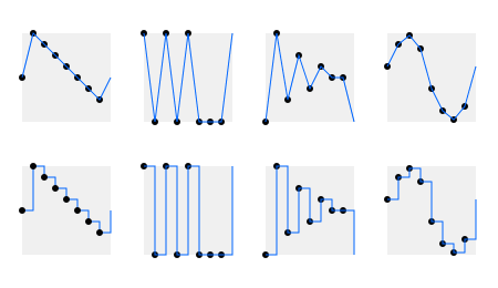
Note that we could either interpolate between the points, which gives us the option to do ramps, more spiky-looking triangular waveforms, or linear-segment approximations to curved waveforms, or we could output the selected points as fixed levels, which enables us to make a selection of interesting pulse waves, staircases, and little sequences. It’s pretty versatile.
Is it possible? Choosing a chip for the job
So how hard would this be? Well, if we do it with a processor, we need quite a few ADC channels. A 14-pin chip would give us 12 input/output pins (IOs). For starters, we need an output, tap tempo input, a Rate control, and a Level control. That’s four IOs. Additionally, it might be nice to have an Offset control (like the StompLFO) and an input to select between providing the output as discrete steps or crossfaded slopes from one point to the next. That’s 6 IOs. That would leave 6 channels for defining our waveform, assuming we can find a 14-pin chip with 10 ADC inputs. Alternatively we could use an 18 or 20-pin chip, which could give us 12 or even 14 channels for defining our waveform.
Version 1 – Starting simple with 8 points
It makes sense to start simple and work up. The 16F18323 is a 14-pin chip with up to 11 ADC inputs, so it’s a good choice. We can use the pin allocation table in the datasheet to sketch out a pinout to give us an idea how this would work:
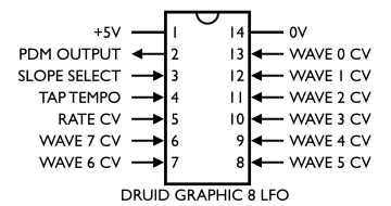
Most of this is pretty obvious. We’ve got eight inputs from the top-right coming around clockwise to define our waveform. After that we have one ADC input for the Rate CV. Pin 4 is a digital-input-only pin, so that’s a good choice for the Tap Tempo input. Pin 3 could be an ADC input, in which case we could add a Level CV, or it could be a digital input so we could add a Levels/Slopes selection. Since level control is easy to do off-chip and the Levels/Slopes control is impossible to do off-chip, I’ve decided to go with that. Finally, we’ve got pin 2 for the LFO output.
What does the code need to do?
The code should be relatively straight-forward. We need an NCO running the show, providing our underlying LFO frequency. I know from experience on other LFO projects that a three byte (24-bit) phase accummulator will give us enough accuracy. We can use the upper three bits of the phase to address the points, and the remaining bits to provide an index to crossfade between them for the “Slopes” mode. The NCO will need to be updated at the output sample rate, so this will be in an interrupt routine.
Meanwhile, the main code needs to scan the various controls (The CV inputs for the waveform points, plus the Rate CV) and update variables as appropriate. It will also need to debounce the Tap Tempo input and monitor it for changes.
In the end, I didn’t do this exactly as I proposed above. It’s more convenient to have the three bits for the Waveform point selection in their own variable, so I essentially added an extra byte above the three bytes of the NCO and used only the lowest three bits. One way to see this is that we now use a 27-bit NCO, right-aligned in four bytes. Another way to see the same thing is to say that we’re running the 24-bit NCO eight times as fast because we have to scan through eight points before we complete our LFO cycle.
Version 2 – Adding more points
Sticking with the same series of chips will make moving the code easier, so I had a look at the datasheets for the rest of the 16F183xx series. There are some 20-pin devices (the 16F18344, 345, and 346). These are the same apart from the amount of memory they have. As this LFO doesn’t store any waveforms it doesn’t need much memory, so I chose the bottom-end version, the 16F18344. This has 2K of Program Flash memory, and even this is too much. The Graphic 8 version above manages with only 1K!
The pinout finishes up being very much the same, except this time we get 14 waveform points:
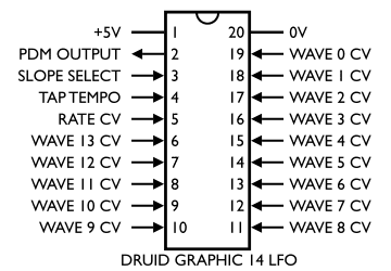
It’s a pity we can’t have 16 waveform points, but there isn’t a 22-pin chip! You could do it on a 28-pin chip, but I haven’t tried that yet. Some of the 28-pin devices claim to have 24 ADC channels, so 16 points should be easy in theory.
So can I play with it? I want a go!
I haven’t done a final version of this yet, and I’ve got no immediate plans to turn it into a Druid chip. You’ll have to program one up:
- PIC 16F18323 assembly code GRAPHIC8LFO.ASM
- Compiled version of the above, ready to program GRAPHIC8LFO.HEX
- PIC 16F18344 assembly code GRAPHIC14LFO.ASM
- Compiled version of the above, ready to program GRAPHIC14LFO.HEX
- GRAPHICLFO datasheet, including schematic diagrams
The schematic diagram is very simple. It has pots for the wave points (and slider pots are really the way to go for a project like this), another pot for the Rate CV, and a button and Sync input attach to the Tap Tempo input. The output on my prototype has passive filtering, and that seems to work ok, but a more finished version could add active filtering as shown in the datasheet.
I can’t compile it! MPLAB throws a wobbly!
This code is written in MPASM. Unfortunately Microchip in their infinite wisdom have dropped support for this compiler (thus making all their datasheet examples non-functional!). I’m still using MPLAB X V4.05, which is one of the last versions that supports it.
Hey! This thing’s just a sequencer!
This chip is pretty much just a simple 8 or 14-step sequencer, yes. Many sequencers have no problem running at LFO rates or even up into audio, and a few even offer the cross-fade feature that generates slopes. That “Slopes” feature is certainly the biggest difference from most simple sequencers. Alternatively, you could filter the sequencer’s output to get this “smoothed” effect, although that requires the filter to be tuned to the sequencer’s output frequency. This LFO chip provides that “tuned integration” feature automatically.
When I realised that there was such a lot of overlap between this chip and a basic analog sequencer, I started thinking about sequencer design, and wondering if I could program a chip that would make sequencer building easy, while still offering all the features we’ve mentioned so far. Since sequencers commonly come in eight and sixteen step variants, it would be useful if we could easily make those options. This chip has eight steps so it seems ideal initially, but we’d need to somehow link two of them together to make a 16-step sequencer. That’s quite tricky, and needs more pins provided on the chip to do it. What about if we wanted to be able to link four simple chips to make a 32-step sequence? Tricky, again. Imagine what happens when we reach the last step of one chip and are about to move to the first step of the next one – how can we do a smooth slope from one value to the next when those two points are on different chips? It’s possible, but it would require intelligent communication between the two chips and it all starts to get complicated.
I think there is definitely a role for processors in modern analog sequencers, but that role is replacing the large amounts of “glue logic” that classic designs tend to have and simplifying the schematic, rather than replacing the actual analog parts of the circuit. Those are probably still best done the traditional way with decoder circuits driving pots.
If I do design a sequencer, I’ll post an article about it!
Feedback and comments
Any feedback or comments about the LFO are appreciated! Please comment below.
These designs and schematics are licensed under a Creative Commons Attribution-NonCommercial-ShareAlike 4.0 International License. Here’s the legal stuff.
Me want! 🙂
I just want to suggest an idea for the chain able sequencer idea:
use a chip that has more pins
you need three pins available for this idea, lets call them – “Available (AV)”, “Not Available (NA)” and “Head”
“Head” – determines which of the chained ICs is the main one to start the sequencer.
AV and NA are chained from one to the other – meaning the AV of each chip connects to the next chip’s NA, and the last chip AV connects to the main chip NA.
this way – every chip “knows” when it is its turn to play.
the outputs can be summed
You’d need some way of tying the clocks together too, but I like your idea, Alon. It’s nice and simple, and infinitely expandable – just add more chips!
I wonder if you would enjoying playing around with something like the STM32G4.
The best tool is always whatever you understand the most, and you clearly have a deep understanding of those PIC chips which is far beyond my understanding of anything really.
But I think you’d have fun at least playing with em, I pay like $2-$3 for the chip when making PCBs
You can get 23 12 bit ADC channels at once.
You can use DMA to read the ADC’s and write to DACS with out using more than a couple CPU cycles
– 2 external 12-bit DAC channels
– 2 internal 12bit DACchannels, can be routed through opamps
4 rail-to-rail analog comparators
• 3 x operational amplifiers that can be used in
programmable gain mode, all terminals accessible
• 14 timers:
– 1 x 32-bit timer and 2 x 16-bit timers
– 2 x 16-bit 8-channel timers
Yeah, a lot of people of the SynthDIY list have done a lot of good things with the STM32 series chips, so I have wondered about it. It might happen. I’ve been writing more C recently, and that’s more portable than my beloved assembly.
Would it be possible to use this as a basis to make single cycle audio waveforms?
Hi Richard,
With this code, probably only up to low audio rates. It’d be ok for basslines, maybe! The trouble is the interp between points is relatively slow since there’s no multiply instruction on these chips. If’d been aiming at audio rates, I might have done things somehwat differently.
Tom
Hi Tom
The idea of sequencing voltages to make oscillator waveforms is far from new, and as you point out it would be essentially a sequencer.
But above LFO frequencies into audio frequencies the idea is also very old – Don Buchla did it in the mid 1960’s.
Take a look at the Buchla 32-step (!) ‘Waveform Synthesizer Model 132’ demonstrated in this video: https://youtu.be/CiqhM-bNBrY?si=3psIx8GkJhhwCzEw&t=1034 at 17:14. Buchla found it tedious to use because turning any one pot (out of 32!) made only subtle changes to the waveform timbre.
A fast-running logarithmic VCO clocking through a smaller number of pots would probably be more effective. I have wondered if a 3340 could be overclocked to produce pulses up into the 160kHz range (i.e.20KHz x 8) and still retain a good musical logarithmic relationship to an input CV. All that might need is a reduction of the timing capacitor from 1nF to about 120pF, but maybe stray capacitances and internal IC switching times might mess up the log relationship. I will experiment if I have the time.
Then take the 3340 pulse output to clock a counter and drive CMOS switches as in a bog-standard sequencer. Or maybe use a PIC.
Personally I prefer wavefolders as they are easier to use and it’s fun designing terribly non-linear circuits for a change.
Thanks Don, many good points.
The other problem with pots-to-waveforms for audio is that the relationship between the waveshape and the sound is not at all obvious. Most people would struggle to draw a waveform containing plenty of 4th, 7th, and 9th harmonic, for example. And even if they did manage it, they’d probably do it by thinking what the sinewaves would look like and then mentally adding them together – additive synthesis in your head, effectively. And people would do that using sinewaves at phase zero. If you start adding phase into the question too, it rapidly becomes too complicated.
The 3340 could probably handle running such a thing though. Wasn’t there an old digital oscillator module that was basically a EEPROM waveform memory with eight address bits driven off a counter, and the counter clocked by a 3340 pushed up into ultrasonic frequencies? I’m sure I’ve got a reference to it somewhere, but I’d have to dig…
I am not familiar with the chips you are using, but to me if you want to time multiple together wouldn’t the way to go be assigning each chip one step on the sequencer? That way all chips are working in tandem at the same rate, only that rate is divided by how many chips you have.
The problem there is how many chips you need! The idea was to try and make things simpler and with less parts.