
First, a quick history of overdrive pedals. Boss got the ball rolling in 1977 with the OD-1, one of the first pedals in their now-famous “compact” series, and the first proper “overdrive” pedal – before that, they were all called “Fuzz” or “Distortion”. This pedal was part of the three releases that started the series, and which were re-released as a 40th anniversary box set!
Maxon/Ibanez followed the OD-1 up with the TS-808 Tubescreamer in 1979, which added a tone control, and tweaked the clipping diodes, but which is otherwise very much like the OD-1. Some sources suggest that the TS-808’s symmetrical clipping was done to avoid a patent on the asymmetrical clipping in the OD-1, but if Boss ever did have such a patent I’ve never found a reference to it. The Tubescreamer was (somewhat unfairly, perhaps) a bigger success than the OD-1 had ever been, so Boss returned the favour and released the SD-1 in 1981. It was an updated version of the OD-1, adding the tone control that the ‘Screamer had, and putting Boss back in the game.
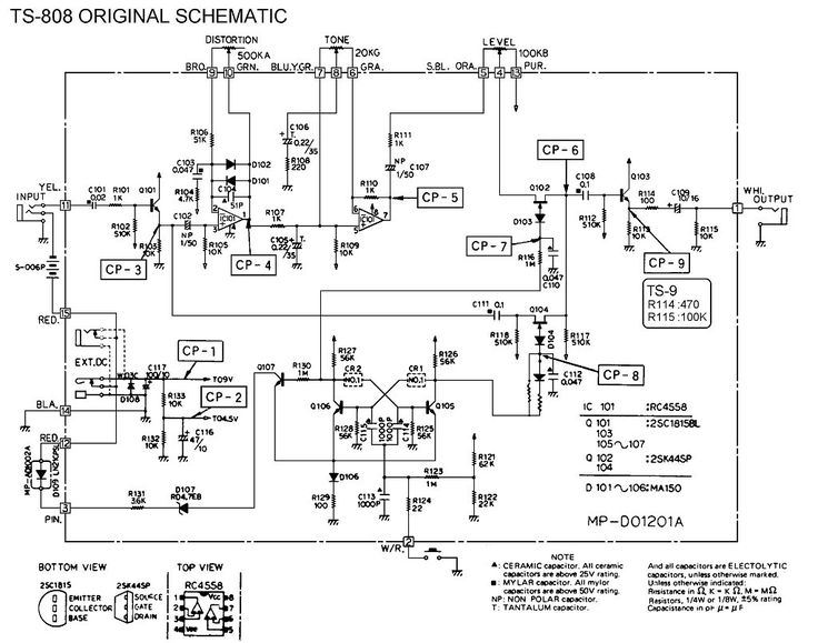
So how similar or different are these circuits really? Let’s have a quick look. Here’s links to the original schematics:
- Boss OD-1 Overdrive schematic
- Ibanez TS-808 Tubescreamer schematic
- Boss SD-1 Super Overdrive schematic
For easier comparison and study, I’ve redrawn these on one sheet and worked out the frequencies of all the tone shaping components I could find. Note that I’ve removed the FET switching that they all use. This switching is the reason for the transistor buffers at the input and output, but we’ll come to that in a bit.
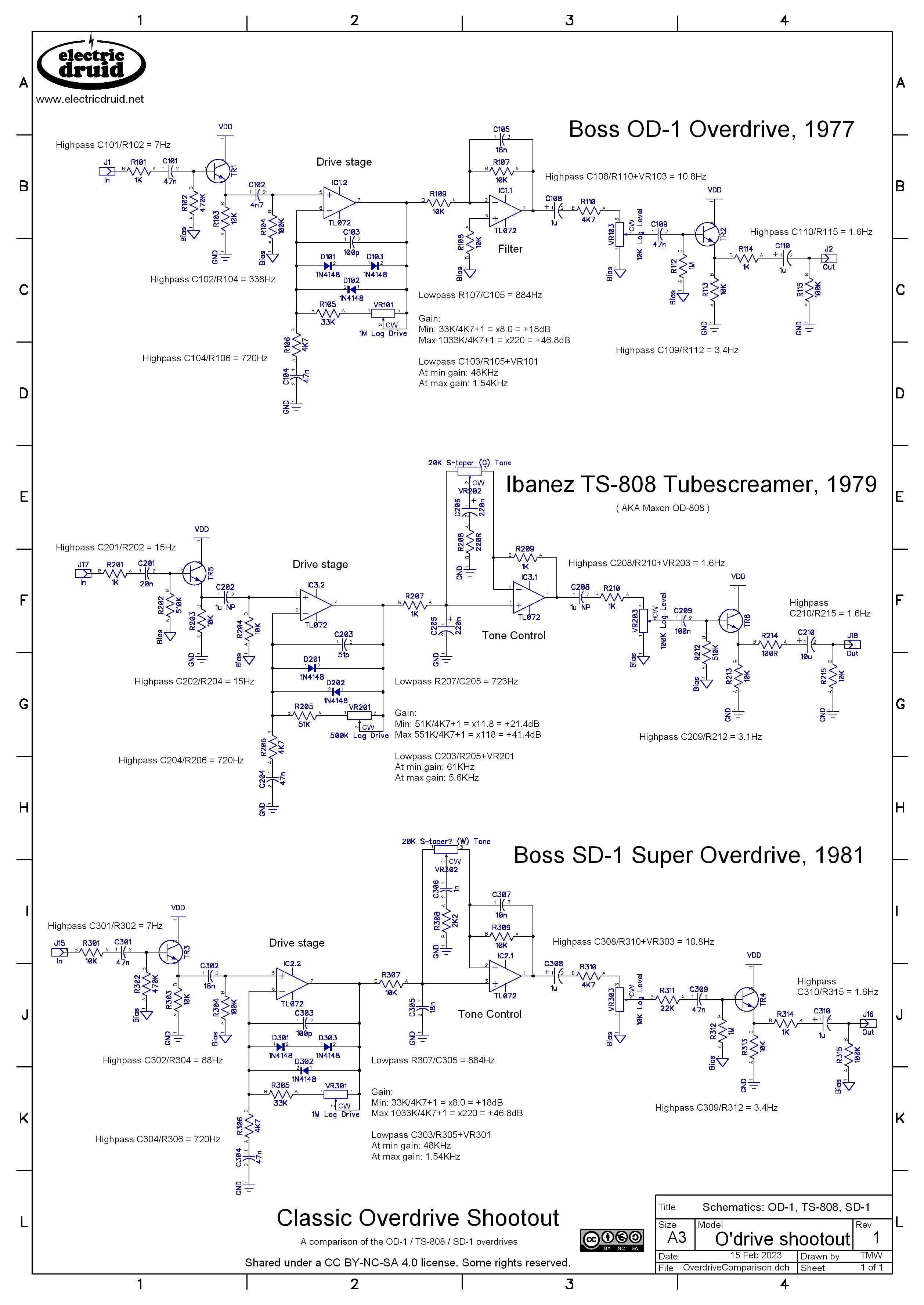
This comparison emphasises just how similar these pedals are. In many places they’re identical, and in many others, the minor alterations make no difference to the performance. Example: Who cares if the input bias resistor is 470K or 510K really?!
I’ve labelled all the components in the first circuit from 100, so 101, 102, 103, etc, and everything in the second is 201, 202, 203, etc, everything in the third 301, 302, 303, etc. As far as possible, components doing the same job have the same number, so C102 is the same component as C202 and C302. In the following discussion, I’ll refer to these parts in general as Cx02.
Now, if we want to design a classic overdrive pedal along these lines, we can use the same recipe and tweak the ingredients.
Building a drive stage
I’d usually start a pedal with a simple non-inverting op-amp buffer like this:
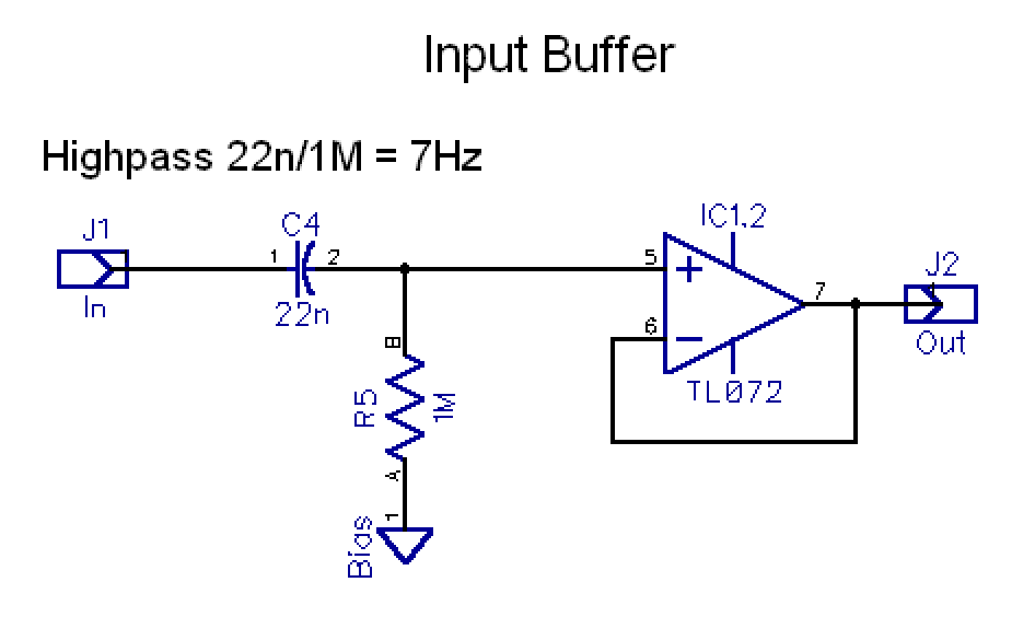
The OD-1 and SD-1 set the input cap Cx01 value to give a highpass at about 7Hz, so we can do the same. I’ve increased the Rx02 input impedance up to a more modern 1M. That gives an input cap of 22n, but anything from there upwards would work fine. Since the cutoff is already way down at 7Hz, there’s no point throwing >1µF electro caps at it “to improve the bass” – it won’t!
One point to note is that none of these circuits have a extra resistor to ground ahead of the cap to bleed off any charge and help prevent pops. Since they used FET switching, it wasn’t such an issue. We could add one if necessary, but I’m leaving it out for now. A 22n cap doesn’t hold much charge anyway, so I don’t foresee big problems.
So why not use a transistor buffer, like all the pedals above? Well, why did they use one? I mentioned the FET switching that I took out of the schematics (you can see the FETs on the original schematics linked above), and they’re the reason why. Here’s what the FET switching scheme looks like in these pedals:

The FET switches go after the input buffer and drive stage, but before the output buffer. Basically, the FETs need separating from the outside world. In some circuits, you see an extra FET ahead of the drive circuit to turn the input off too, but they didn’t bother with that here. The flip-flop switches on one or the other FET to select either the signal coming from the drive circuit, or the signal coming from the input buffer. Note that even when the effect is “off”, there are actually two buffers in the signal path. The typical way to convert one of these pedals to True bypass switching is to simply take the flip-flop and the FETs out and then stick a switch around the outside, like this:

Although this is simple to do, especially if we’re starting with an original pedal, it leaves a lot of unnecessary parts in the signal path. If we drop the FET switching, we can drop the buffers too. That gives us something that looks like this:

As long as our drive circuit has a good input impedance, we’re fine. Our non-inverting op-amp is perfect in this regard, and we have 1M to the bias supply to set the input impedance. Let’s turn it into an overdrive, not a buffer.
The buffer can easily have gain added, and clipping diodes. Since I try to only keep 10K and 100K pots around, I’ll put a 100K in for the Drive pot, and then scale the resistor values to fit this. Using 100K/1K gives us a Tubescreamery x101 gain, so that’s a good start.

Remember, this is a non-inverting amplifier, so the gain equation is:
Gain = (Rf / Rg ) + 1Rf is the feedback resistor (the pot, in our case) and Rg is the resistor to ground.
We could add a series resistor in series with the pot to set the minimum gain, which will go to unity otherwise. We’re looking for x8 or x10 or so, so 6K8, 7K5, or 8K2 would be good choices. I’m going with 6K8, which sets the minimum gain to x7.8, +17.8dB. That’s more like the SD-1 than the TS-808 which is a little bit hotter at minimum, but there isn’t much in it. The extra series resistance bumps up the maximum gain just a little bit too, to x107.8, or +40.6dB. That should be enough for a decent overdrive without pushing us into distortion or fuzz territory.
We also need to make a choice about the clipping diodes. We could go for symmetric like the TS-808, or asymmetric like the Boss pedals. I’ve chosen asymmetric, since it gives more options – I could put a wire link in for one of the diodes if I want to build a TS version one day.
We also need to think about the capacitor selection. The original circuits all use a cap that sets a highpass cutoff at 720Hz. The idea of this is to compensate for the fact that lower notes on a guitar (the thicker wound strings) are much louder than the high (thinner, unwound) strings. In our circuit, the 1K resistor works with the capacitor to ground to set a highpass filter cutoff point. This is Rx06/Cx04 in the schematics. To get 720Hz with 1K, we need a 220n capacitor. You can check that over on the Filter Calculator page.

Note also that because we’ve added a capacitor, we no longer have to terminate the bottom of the feedback network to the Bias voltage. Since the capacitor blocks the DC, we could (in theory) use any voltage level, so we connect it to ground. Generally it’s a good idea to only use a “virtual ground” bias supply where necessary, so “proper” ground is preferred here.
All the circuits also limit the gain at high frequencies with Cx03. This cap is handy because it is interactive with the gain control – more gain gives you a lower cutoff, so it acts to smooth the drive more as you turn it up. The Tubescreamer does less of this at this stage than the Boss pedals, but the filtering still comes down to 5.6KHz at max gain. I’ve “split the difference” between the 1.56KHz of the Boss pedals and the Ibanez and gone for 3.1KHz.
Looking at the tone control
The biggest change Ibanez made when they modified the OD-1 to create the Tubescreamer was the addition of the tone control. It consists of two parts. There’s a simple RC lowpass filter on the way in, and that is followed by a EQ-style tone control that can provide boost or cut. Let’s have a look at it.
Here’s the original circuit in the sim, including the lowpass filter at 720Hz (R4/C1):

And here’s the response:
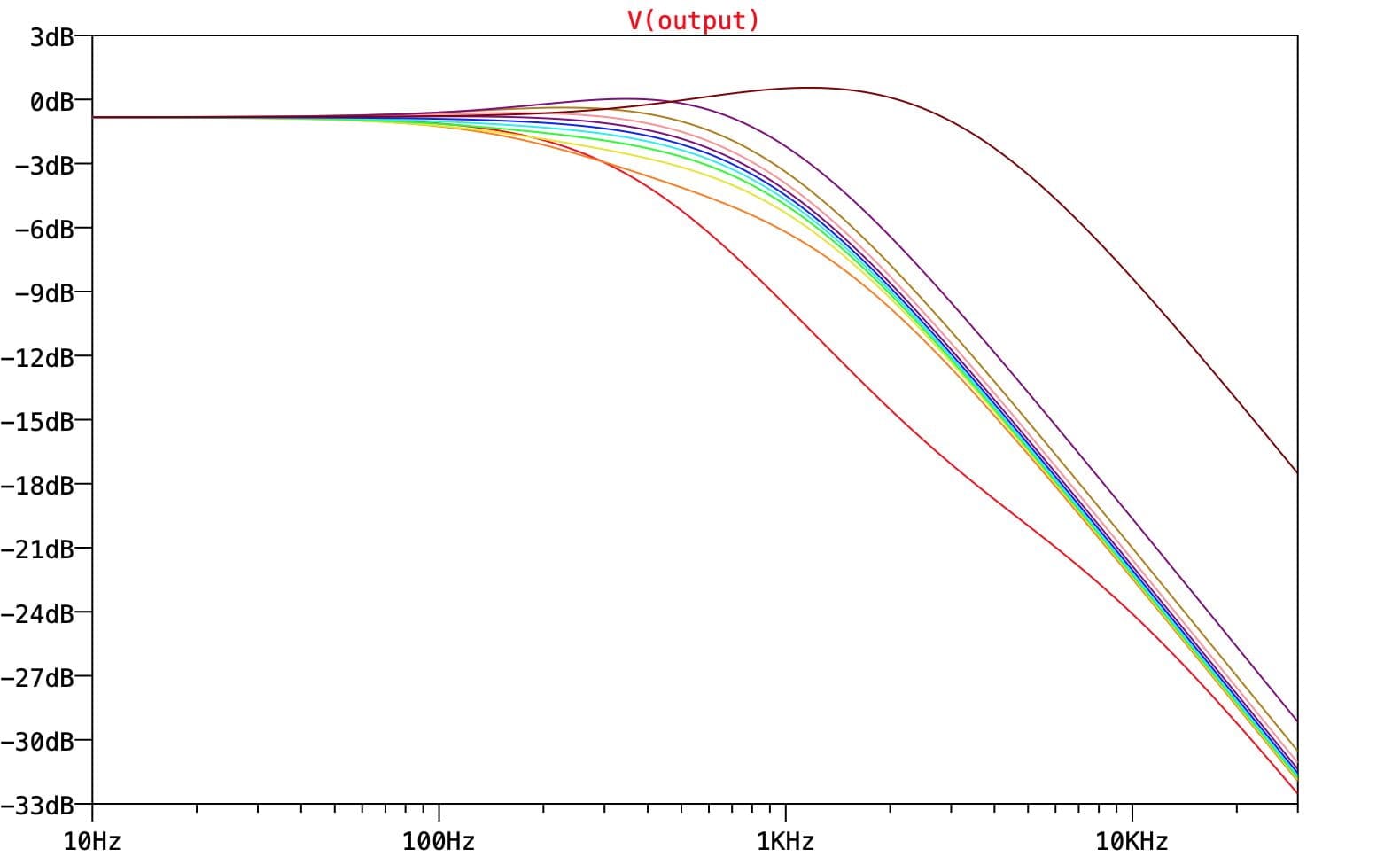
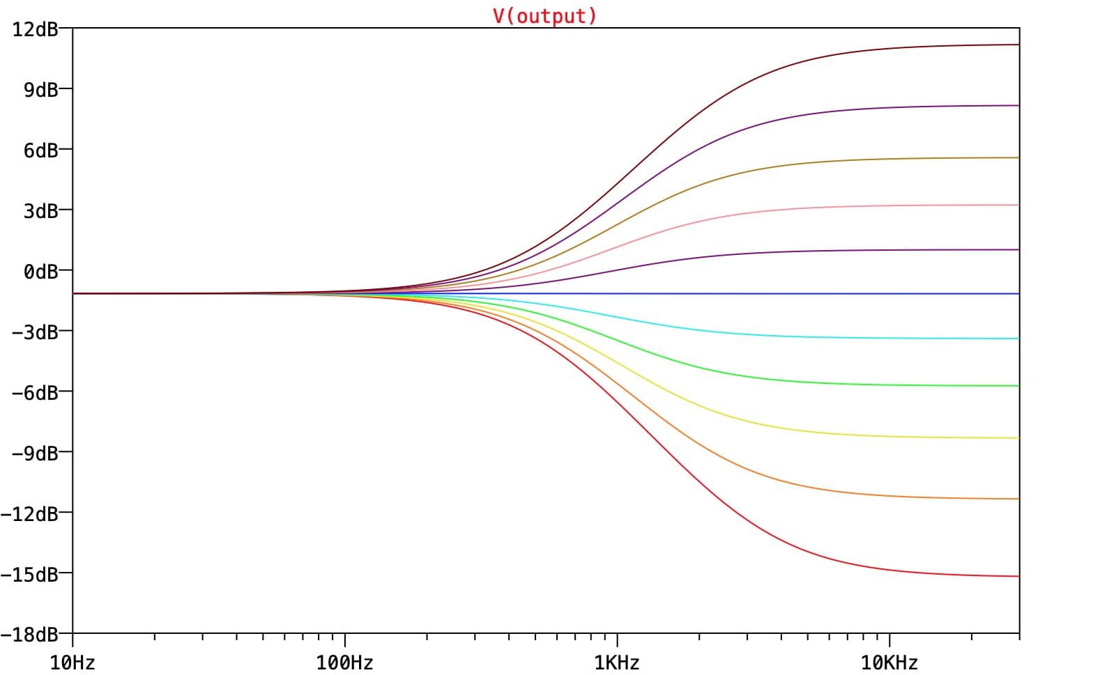
As you can see, it provides a basic broad boost to the treble, with perhaps a slight hump around 2KHz or so. What’s going on with all those lines clumped in the middle though?!? The sim is set up to show us the output every 10% of the way around the Tone pot values, so the pot feel looks wacky. We can see what’s going on better if we remove the 1K/220n lowpass filter and plot just the EQ response:
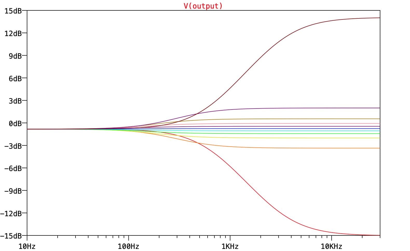
This makes it clear what is happening. We can see that this EQ provides a cut/boost of about +/-15dB, but that only the extreme settings really do anything (from 0% to 10%, and from 90% to 100%). 80% of the pot’s travel is all bunched up in the middle doing not a lot. Ibanez were aware of this and used an unusual S-taper pot to counteract the effect and to help spread out the middle settings.
However, it’d be nice if we could avoid the need for some strange pot taper. Luckily, if we change the EQ stage for a different circuit design, we can sidestep the problem.
Here’s a Baxandall-style replacement, again with the 720Hz lowpass in front of it:
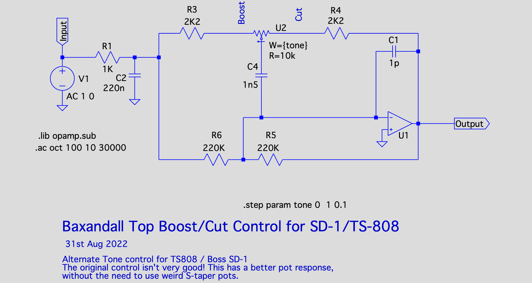
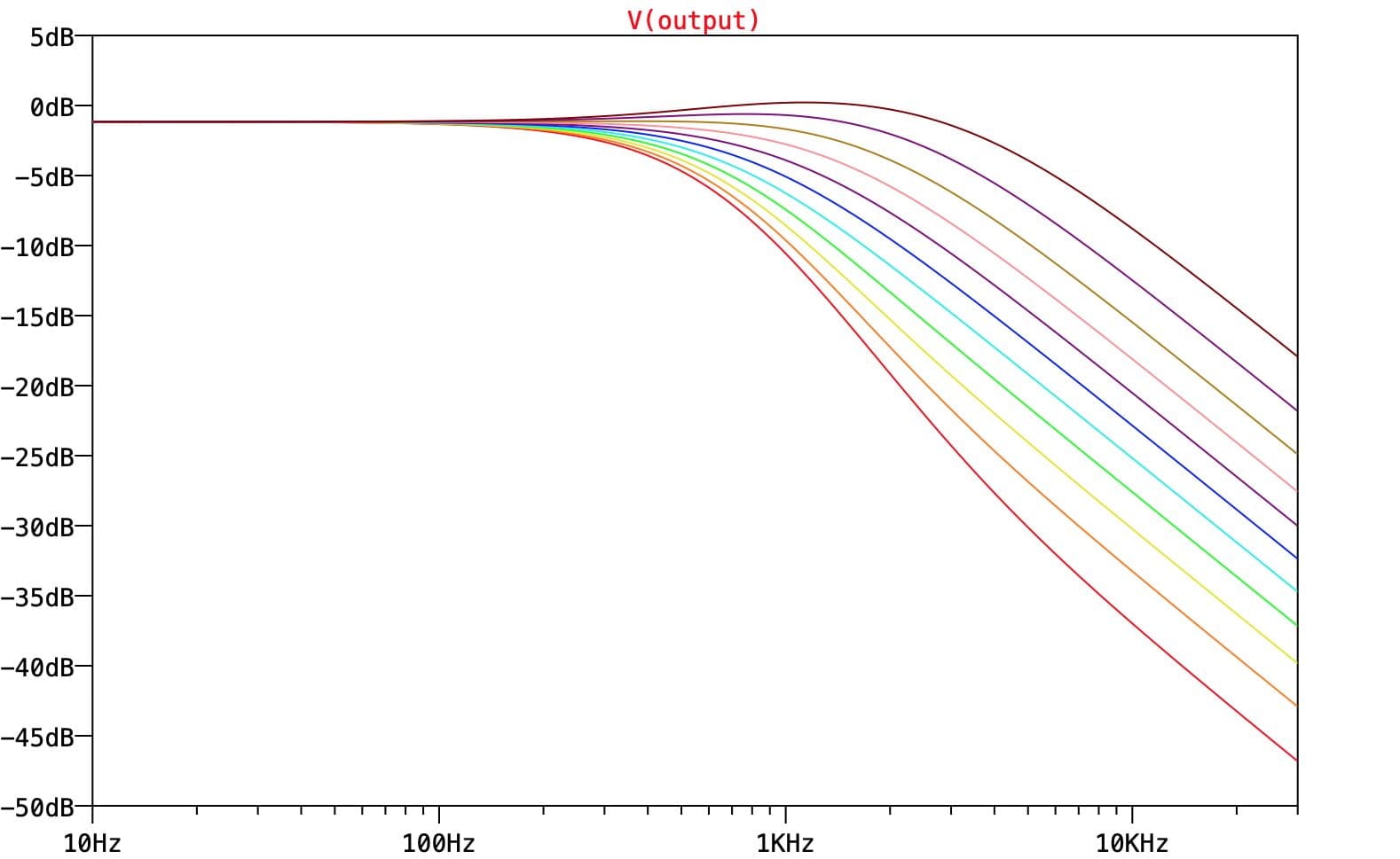
And here’s the response, ignoring the lowpass filter – it’s basically the same, except now the lines are much more evenly spaced, so no weird pot is required:
Putting the 720Hz filter back in front gives the following response. Compare this with the one further up the page and consider how much smoother the pot feel will be with just a simple linear pot.
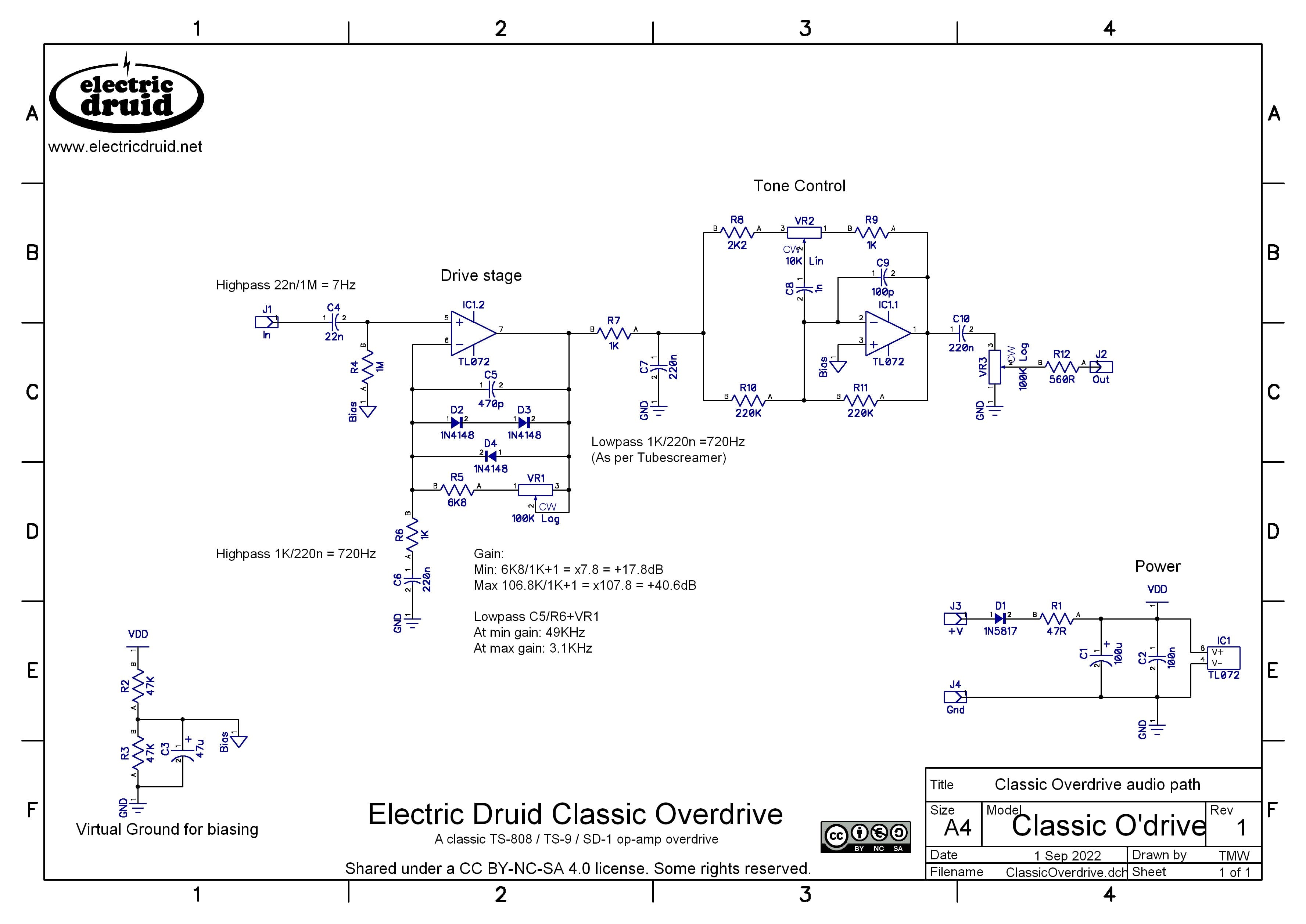
If we add this “new improved” tone section onto our drive stage, we have a complete classic overdrive with only one dual op-amp chip.
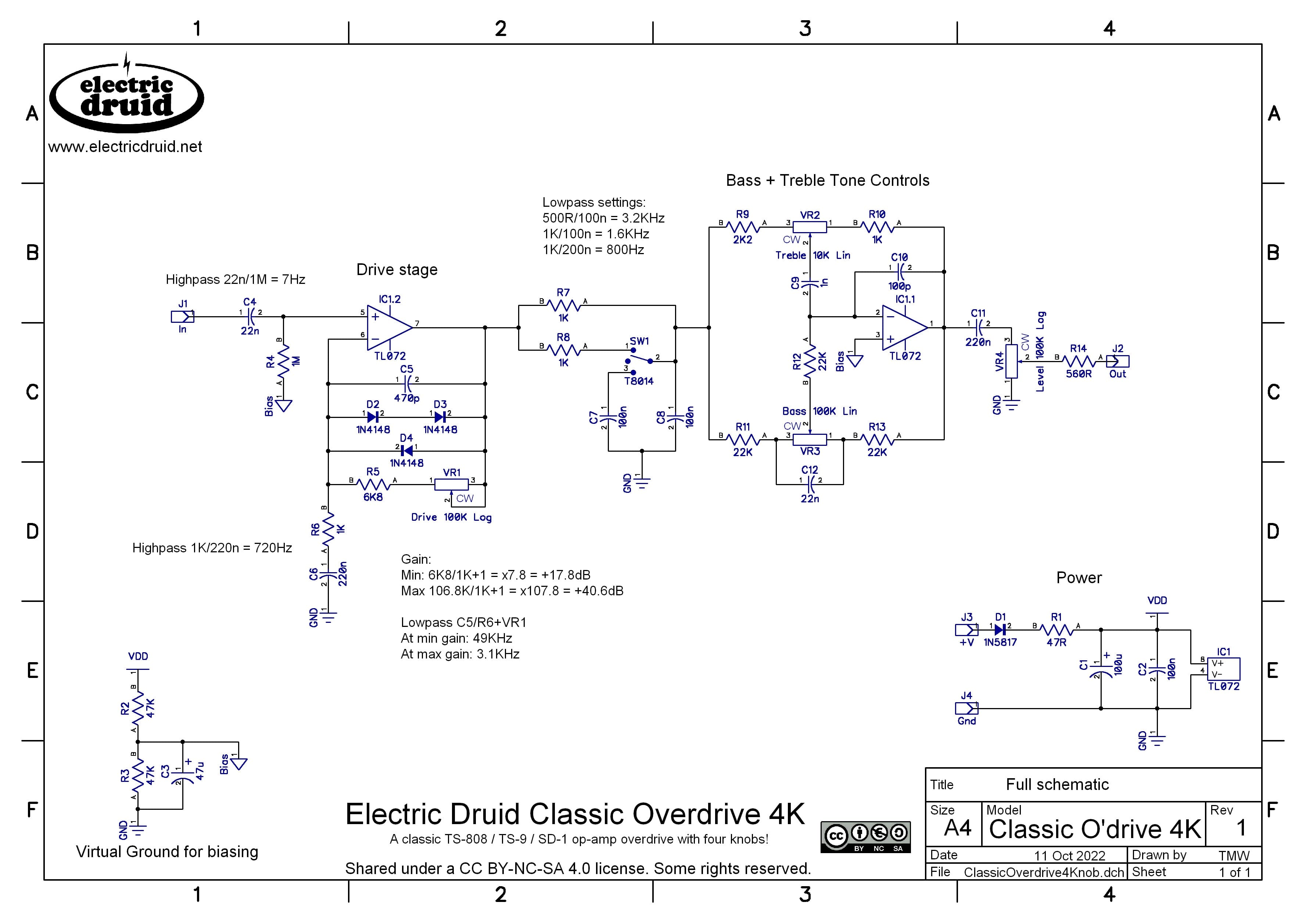
That covers the basic three-knob overdrive. But since we’ve got a Baxandall tone control in our circuit now, it would be easy for us to add a “Bass” control as well as the “Tone” (“Treble”, really) that we already have. We could also throw in some options for that pre-tone lowpass filter using an On-Off-On toggle switch. That gives us this, the fully-tricked-out Classic Overdrive 4-knob version (“4K”).
Of course, I’m not the first person to consider adding a Baxandall tone section to a OD-1 or TS-808. That’s basically what the Xotic BB Preamp is. Aion FX did some excellent work tracing the various versions, which is worth a look. So if you fancy building a $200 boutique overdrive pedal for less, now you can!
Going further
There’s plenty of opportunities for modifications in a circuit like this. I’ve marked up all the main tone-shaping components, so you can experiment changing capacitor values. Remember, doubling a cap’s value (so up from 4n7 to 10n, from 10n to 22n) will lower the filter frequency by an octave. Halving the cap value takes it up an octave. You can tweak both the bass and treble response in the drive stage, which will alter the “feel” of the pedal and the amount of harmonics it produces. After that, there’s that critical RC combination on the way to the tone control. Again, you can tweak this either brighter or darker and see what you think. The other favourite mod for stuff like this is to experiment with different diode combinations – silicon diodes, germanium diodes, LEDs, whatever.
Feedback and comments
Any feedback about the pedal is appreciated! Please comment below.
These designs and schematics are licensed under a Creative Commons Attribution-NonCommercial-ShareAlike 4.0 International License. Here’s the legal stuff.
Back to your roots eh… not a PIC in sight.
A very good and thorough article as ever.
I have a Boss DS-1 distortion pedal (not the SD-1 as analysed above) and often wondered whether it was worth getting an “overdrive” variant for a more “valve-like” sound but I don’t think I’ll bother now. I don’t know what’s inside my pedal but I imagine its much like the SD-1 but with symmetrical clipping. And thanks to your article I could always recreate the SD-1 circuit or your version if I felt so inclined.
Many thanks Tom.
No PICs? No reason the thing can’t be made programmable/MIDI controllable! 🙂
Hohoho! No, no PICs in this version at least. I *have* actually played with the idea of a programmable ovedrive, using the MCP42xxx series digital pots and MCP6002 op-amps so the whole thing runs at 5V. It worked, but was somewhat underwhelming, so I haven’t done much more with it.
Further to my previous post I have now seen a schematic of the DS-1 and the (symmetrical) clipping diodes are not in the feedback loop of the gain stage but after it, as in your Hard Bargain distortion pedal design, so it will have a harder clip.
As an aside regarding the “overdriven valve sound”, I have a Marshall guitar amp that has a valve pre-amp/gain-stage but a transistor output stage and when the gain is cranked up and master volume lowered the distortion is not noticeably different to transistor/diode clipping (to my ears anyway).
A mentor of mine once said that the characteristic overdriven valve sound may well be from the fact that fully valve amplifiers have output transformers and the characteristics of these combined with the relatively high output impedance of valve stages colour the sound in ways that transistor amps don’t. Obviously valves do clip in a different way but the complete signal chain should be considered.
Thanks for this article and elegant approach! Just wondering, would opting for the clipping diodes to be switchable be enough to allow this to offer a ‘clean’ boost option?
Yes, that’d pretty much do it. Without those diodes, it’s a clean boost. You’d have to consider the headroom, since you’ll clip the op-amp if you boost too much, and you might want to change the tone shaping for a clean signal rather than an overdriven one. But it’ll work.
Hello Tom
For circuit like this, how to add clean blend(dry/wet combination). Example, Wampler hot wired v2. Or some dumble-ish pedal (timmy based). I dont know about theory or math. Im just solder jockey.
Thanks
You could add a wet/dry mixer stage like the one that is discussed in the Slapback Echo article. That output mixer stage basically does exactly what you want. I used the same circuit for the same purpose in the PTWobble modulated delay too, so you could have a look at that. It’s a very handy “building block” circuit.
Aha! Will try. Somehow, hate to rework this ELDruid_COD_3K. Or maybe time to build smd-ish daughterboard.
Thanks for the circuit. Had fun build.
Well, I understand why you’d hate to mess up something so tidy! Adding an op-amp for a wet/dry mix is back to that “three op-amps” problem I always try and avoid.
A simple passive mix would be the usual solution, but in this case we don’t have a good source of the clean signal since we’ve got no input buffer, so it’s a bit hard to see how to do it.
that why the question came for this bufferless. Tried add buffer in front, then make me remember sparkle drive and my version of moonshine-ish.
I do like sound from Gladio SC, but hate circuit. I think overkill. Timmy derivative, but 3 opamp(?).
Hi, many thanks for this detailed article!
I’m building an Eurorack version with a 3 band baxandal and some additions here and there (bipolar power supply, switchable hard&soft clipping, switchable High pass for bass preservation, sockets for diodes etc…)
Some questions:
On your final schematic, the R6/C6 look like a Lowpass not an High pass or I’m wrong?
Also, as the second Op amp for the Eq is in inverting mode, is there a particular reason for inverting the signal here?
R6/C6 are a lowpass, but they’re in a negative feedback loop, so the effect is reversed. That’s why it’s a highpass.
The EQ op-amp is inverting because that’s the best way to make an active baxandall circuit. You sometimes see a passive version followed by non-inverting gain, but there’s a noise penalty to that because you reduce the signal level and then amplify it. I don’t think I’ve ever seen a active non-inverting version.