
 I recently saw an advert for the new EHX Slapback Echo reissue pedal and thought it was a cool little thing and would make a nice project. The original pedal came out in 1978 and was about as simple as it could get. There was one “Blend” knob to mix the straight and delayed signal, and a “Filter” switch for a bit of tone control. It wasn’t a great success. Everyone says the sound is too dark. The new one makes several improvements. As well as the “Blend” knob, it also has a “Boost” knob, and instead of the Filter switch, it has a three-way selector for delay time (the original was fixed at 100msec, I think). It’s also in what EHX call a “Pico” enclosure, which is basically a Hammond 1590A, so it’s a tiny little thing compared to its hulking ancestor.
It’s not a complicated pedal, and it’s a bit of a one-trick wonder, but slapback is a great sound so if the one trick is a good trick, why not build one?
What does the EHX Slapback pedal do?
If you want to hear it, pop over to EHX’s page about it and listen to the sound samples. The basic effect is a single, short echo followed by a decent boost you can use to drive the front of the amp if you want to. The webpage and the manual are very helpful and give us most of the details we need to build a workalike unit. This is not a clone, since I’ve never seen an original unit, let alone seen inside one or seen the schematic. The controls are:
- Boost, 0dB to +20dB (x10 gain)
- Blend, 100% Dry to 100% Wet
- Time, 45ms, 65ms, or 100ms.
How would we build a workalike slapback echo pedal?
We start the pedal the same way we always do, with a nice solid buffer to give a good input impedance and provide a reliable signal for the rest of the circuit. I’ve discussed this circuit several times before, so I’ll summarise it here. It’s a non-inverting unity gain op-amp. R4/1K helps prevent damage if someone shorts the input or applies too much juice. R6 provides the 4.5V bias for the op-amp input, and the signal comes in via the C6/220n cap. These two components produce a highpass filter with a cutoff frequency of 1/ (2 x Pi x R6 x C6), which is way down, so no bass gets lost. R5 provides a way for any charge on C6 to leak away to ground. Note C6 is larger than necessary, but I used 220n caps in other places in the circuit and wanted to limit the number of different values used. Since the required delay times are short, I thought the PT2399 would be a good fit since it can produce a good quality echo in this range. The noise and distortion that it’s somewhat notorious for are mostly a result of people pushing the delay out to 500msecs or more, at which point it does start to get pretty crunchy. The PT2399 datasheet actually gives a maximum delay of 343msecs, so going another 50% beyond that is definitely stretching what it can do to breaking point! That’s no problem for us though. 100msecs is well within its capability and it will operate comfortably with low noise and distortion while doing it.
What resistor values do we need to get those delay times?
The PT2399 uses a resistor from pin 6 to ground to set the delay time. But what resistor value gives the time we want? The information we need is over on my page “Useful design equations for the PT2399“:
Delay msecs = (11.5 * Resistance KΩ) + 30
We rearrange that to give us the resistance from the delay time instead:
Resistance KΩ = (Delay msecs - 30) / 11.5
I’ve rounded this to more sensible numbers, but it’s close enough. So if we need 45, 65, and 100msecs, what resistor values do we use?
Resistance KΩ = (100 msecs - 30) / 11.5 = 70 / 11.5 ≈ 6K
Resistance KΩ = (65 msecs - 30) / 11.5 = 35 / 11.5 ≈ 3K
Resistance KΩ = (45 msecs - 30) / 11.5 = 15 / 11.5 ≈ 1.3K
We could use a DPDT On-On-On switch to select between three resistors, but an SPDT On-Off-On switch is cheaper and takes up less space. Like this, we’d have a default resistor to give us the longest time, and then add other resistors in parallel to get the shorter times. The only advantage of the DPDT is that the times can be in order, Short/Medium/Long, whereas with the SPDT, the longest time is always in the middle “Off” position, so Short/Long/Medium.
The nearest common value for the long resistor is 6K2, which gives us 101.3msecs according to the equations. Adding 6K2 in parallel gives an effective value of 3.1K, which is 65.65msecs. Adding 1K8 in parallel gives an effective value of 1.4K, which gives us 46msecs.
When I tried these values in the prototype, I got slightly different results depending on which batch of PT2399’s I used. One old batch I tried gave 40, 60, and 100msecs. The newer ones I have gave 45, 65, and 105msecs. This variation in the PT2399 means it’s not worth stressing too much about super-exact resistor values. It’s all close enough for rock’n’roll.
Delay filtering
There’s one bit of information which we don’t have about the EHX design, which is what frequency they set the lowpass filters at. A typical delay needs filters both in front of it (to prevent aliasing) and after it (to remove clock noise and reintegrate the signal). Assuming they used a 2048-stage delay like the MN3208, the clock frequency would be around 10KHz and the filters would probably be set around 3.3KHz (the MN-series datasheets recommend filtering at a third of the clock frequency). That fits with the “very dark” reputation that the pedal has, so it’s probably a reasonable guess. We can do better than that, and I opened up the cutoff frequency by a little over an octave to 7.7Khz. This gives a significantly brighter tone. If EHX used a 4096-stage BBD in their modern version, they could have opened up the filters to 6.6KHz, which is much more like the ballpark where we’re playing. I don’t know what they’ve done. But I like the decision to go brighter. I use the Okawa Filter Design Tools for jobs like this. The PT2399 is set up for multiple-feedback filters, and the tools allow you to design those by entering a required cutoff and resonance (the Butterworth resonance of 0.707 is typical), or by entering values to see what you get. I usually start off with the cutoff and resonance, and once I’ve got a first draft, I usually go back and forth a few times tweaking values to get something that doesn’t use any hopelessly unlikely part values and still gives decent performance.
Note that IC3.1 above is actually part of the PT2399 chip. There are two op-amps provided on the chip, specifically for these input and output filters.
If you felt the filters were too bright, swap C10 and C11 for 470p and 4n7 instead. That backs the cutoff down to around 5.4KHz.
Blending Wet and Dry signals
The Blend knob offers a full blend from 100% dry to 100% wet. There are basically two types of Blend knob you see on delay-based pedals. One type mixes the dry signal in permanently, and then allows you to add wet signal as well, with the maximum amount of wet signal usually being the same as the dry level, so a 50/50% mix of wet and dry. This is easily done with an op-amp mixer circuit, as shown below.This type of control shows up on old Boss stuff a lot, where they use a FET switch to disable the Wet path to switch the effect on and off.
The second type is the type we need, and is closely related to the panning controls found on mixers. This circuit can be configured to either mix between two inputs (which is what we need) or to send one input to two destinations (which is what a panning circuit does). R.G.Keen provides a fantastic document looking at these possibilities called “Panning for Fun” over on his website.
Adding some boost
The final part of the circuit is a simple boost. Again, there are various ways we could do this. One obvious way would be to stick a non-inverting op-amp gain stage on the end, with the gain wired up to go from unity (0dB) to x10 (+20dB). The trouble with this is that op-amps come in packages of two and four, and if we did this we’d need three! (One for the buffer, one for the blend, one for the gain). Luckily, there’s a neater way. The 51K resistor in the blender op-amp’s feedback path sets the output level, and 51K is set for unity gain overall. However, we can increase that value to give some gain. 510K would give x10 gain, and that’s very usefully close to the value you get with 51K and a 470K pot in series. 51K sets unity (0dB) as the minimum gain, and 470+51 = 521K sets the maximum gain.
 The only downside with this idea is that the op-amp is inverting, so there’s an inversion of the signal overall. Given that the delayed signal won’t be in phase anyway because of the delay, I don’t regard this as a big problem. It’s worth it to save the inconvenient extra op-amp, and it keeps the whole circuit down to only two chips.
Power supply
The only other part we need is the power supply. Like the buffer, this is standard stuff. We have a 9V input, with D1 for polarity protection, and R1/C1 to provide some power supply filtering. C2 bypasses the op-amp supply, and the 78L05 regulator provides a +5V supply for the PT2399. Because of the PT2399 running on a fixed supply, there’s no point trying to run this circuit at a higher voltage to get more headroom. It works for the buffer and the blender, but a higher signal level will just give more clipping in the delay, so there’s no real point. It will also make the 78L05 regulator get hot, since it’ll have to drop a lot of voltage to maintain a 5V output.
We also need a “virtual ground” 4.5V bias supply for our op-amps, so R2/R3/C5 create that.
The final circuit
Here’s what the final thing looks like:

This was my Rev.1 PCB getting fitted into the enclosure. Notice I screwed up and drilled the hole for the DC jack in the wrong place (half under the board!). I also melted the corner of a cap while fitting the switch. Nothing too serious, just the usual frustrations.
I’m glad to say the PCB worked first time though, which is pretty unusual, so that was nice ;).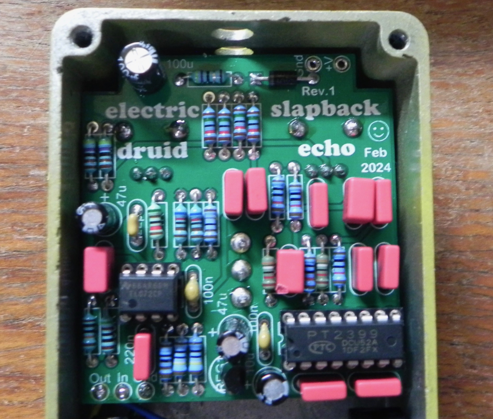
Using the Slapback Echo pedal
While the obvious applications of this pedal are to get that 50’s Rock’n’roll or Rockabilly sound, there’s other things you can do with it too. It’s providing a single delayed copy of your signal, so it’s good for “double tracking” type sounds as well. You can increase the effectiveness of double tracking by making sure the two sounds are not identical. Rather than just adding the slapback last in the chain, use a splitter to create two paths and delay one of them using the Slapback set to 100% wet. Use different effects on the two paths. This gives you the sound of two guitarists playing together much more convincingly than simply adding a single repeat to one sound.![]()
Experiment! There’s quite a lot this little circuit is good for!
Feedback and comments
Any feedback about the pedal is appreciated! Please comment below.
Not related to the project as such but since this chip is so cheap, you could use several of them to build multidelay-line effects, such as chorus with antiphase delay modulation like the Boss Dimension C pedal, or a “through-zero” flanger.
petervis.com has some interesting observations about the PT2399. For instance the ”pin 6 hack” :https://www.petervis.com/guitar-circuits/pt2399/pin-6-hack.html
Thanks for that, I hadn’t seen that site. There’s other versions of the “Anti-latch-up” circuit on the web. Electrosmash have one version, but they almost certainly didn’t come up with it:
https://www.electrosmash.com/pt2399-analysis
It may have come from this discussion on DIYStompboxes.com:
https://www.diystompboxes.com/smfforum/index.php?topic=86297.msg1133704#msg1133704
Taking the resistance between pin 6 and Ground as low as 1K3 (45mS delay) may be a bit risky. I haven’t tested it, but according to an article on electrosmash “PT2399 Analysis”, “if the delay resistance from pin 6 to ground is less than 2kΩ [after power on] then the PT2399 may latch-up, which will make the chip to crash and stop”. “After the first 400ms, the pin6 resistance to ground can go as low as needed.”.
A simple anti latch-up circuit is offered in the article if you want to go below 2k.
I expect you are aware of the article, you are credited in it.
Yes, I know about the Electrosmash article. Thus far, I haven’t had any trouble with latch-up. If I do a PCB design for it, perhaps I should include the anti-latch up just in case. You can always leave the parts off if it’s not needed, after all.
I appreciate this write up. I am trying my hand at the circuit and I have it working, but I am encountering two issues I can’t seem to sort out.
1- the effect is really dark. When engaged, it sounds like my tone knob was rolled way off. The bypass signal is not effected in this way.
2- the blend knob is very subtle. Also, when I attempt to go fully wet and turn the pot all the way, the signal cuts out.
Any advice or areas to focus on as I try and hunt down the cause of my problems? Still teaching myself about effects and building up my troubleshooting skills.
This definitely sounds like there’s still a few bugs to find.
(1) This is probably a fault in the filters. Check how you have R14-19 and C9-14 wired up. Those parts are the input filter ahead of the delay, and the output filter after it, so it’s likely there’s a mistake somewhere there.
(2) This isn’t right. The blend pot should go cleanly from all wet/delay at one end to all dry/clean signal at the other, with a mix in the middle. It shouldn’t cut out at any point. Check how you’ve got R7-11 wired up, along with that pot. There’s likely a mistake there somewhere.
Good luck!!