
Direct digital synthesis is a common technique for generating waveforms digitally. The principles of the technique are simple and widely applicable. You can build a DDS oscillator in hardware or in software.
A DDS oscillator is sometimes also known as a Numerically-Controlled Oscillator (NCO).
How does it work?
The most important part of a DDS oscillator is the ‘Phase Accumulator’. This is just a counter. For example, we could use a 16-bit binary counter:
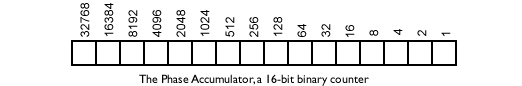
When the counter reaches its maximum count it ‘wraps around’ and goes back to zero – this is the typical behaviour for binary counters. Imagine what the incrementing counter output would look like over time if we plotted it:
Bingo! That’s a pretty good start! We’ve got a ramp wave already. Now imagine what happens if we increment the counter by two each time instead:

The counter jumps up twice as quickly, so it reaches the maximum value twice as fast, and the frequency of our ramp wave goes up an octave. If we double the increment again, to 4, the frequency doubles again too. We can continue up the octaves.
So how do we get notes inbetween?
Whilst being able to generate ramp waves at various octaves is useful, it’s not enough. A octave is a frequency ratio of two, and our increments have that same ratio. If we use the musical ratio for one note higher, we can work out the increment we’d need for the next note up. The ratio of the frequency of one note to the next note up is the twelfth root of two, or 1.05946. Thus if our lowest note (let’s call it “Bottom C”) is produced with an increment of one, our next note is produced with an increment of 1.05946. Unfortunately, our counter only counts whole numbers. We can get round this by using a bigger counter and multiplying all the increments up too. For example, we could replace our 16-bit counter with a 32-bit counter and multiply our original increment by 65536 (216 = 65536). This effectively gives us 16 bits of accuracy beyond the radix point – it isn’t a “decimal point”, since we’re in binary. This way our Bottom C is produced with an increment of 65536, and the C# above is produced with 65536 x 1.05946 = 69433. Note that this still isn’t exact (the true figure is 69432.973352) but by continuing to increase the size of the phase accumulator, we can reduce errors to whatever we deem acceptable.
By setting the increment value to different values, we are able to produce different frequencies. This increment value is therefore known as the “Frequency Increment”. Note that it might not have to be as large as the phase accumulator, for example, we could add a 24-bit frequency increment to a 32-bit phase accumulator. This eliminates the very highest frequencies we can generate, but that probably doesn’t matter.

What about other waveshapes?
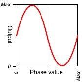
This is the clever bit! We don’t have to output the value of the phase accumulator directly. Instead, we can use it as a address value into a waveform data table stored in memory. This table provides the output value for each input phase value. This wavetable allows us to output arbitary waveforms at any frequency. The output value can either be fed to a DAC to produce an analogue audio signal, or can be kept in the digital domain for more processing.
An example output is shown below:

Also remember that we’re incrementing by more than one, so we’re skipping samples from our wavetable. In practice, we don’t use the whole phase value as an address value into the wavetable, since that would need too much memory. A 32-bit phase value would need 4Gb of memory! Typical wavetables use the top 10-bits of the phase accumulator as the lookup value. This only needs 1024 values in the waveform table. Consequently, unless our frequency increment is large enough that it changes the top 10-bits of the phase value, we won’t skip any samples in our table.
That’s amazing! Why doesn’t everyone do it that way!?
The usual digital reason – aliasing. If the waveform in the table has frequency components that would go beyond the nyquist frequency when transposed to the output frequency, we’ll get aliasing distortion. The only real way around that is to use a higher sampling frequency. Increasing the sampling frequency then means that the increment needs to increase by the same factor for a given frequency. There are tricks you can use instead, like using a series of wavetables with differing harmonic content for different frequencies, ensuring that higher wavetables don’t have frequencies above nyquist.