
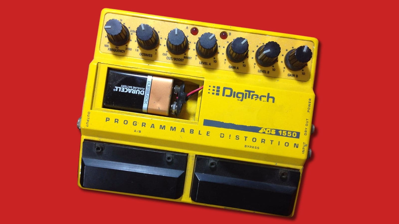
The Digitech DOD PDS-1550 was a member of the 1980’s Digitech “Dual pedal” range. It’s a pretty weird thing, and that’s partly why I’d like to take a closer look at it here. During my analysis of this pedal, I’ve discovered its dirty secret.
Let’s get one thing out of the way early on though – despite being called a “programmable distortion”, it’s not programmable in any sense we’d understand today. “Tweakable” is more like it. You can open up the back and twiddle some little pots and switches, so it actually has more controls than they put on the front panel. Since that front panel has seven controls already, this is a pretty flexible pedal.
The PDS-1550 has a dirty secret – It’s a HM-2 Swedish Chainsaw in disguise!
What, really? Yes, really! The Metal Distortion channel of this pedal is pretty much identical to the Boss HM-2 pedal, affectionally known by fans as the “Swedish Chainsaw”. The PDS-1550’s Channel A has the same distortion stage, followed by the same gyrator-based tone shaping. It adds a few things, but all the bits of the HM-2’s distinctive sound are there. So if you want a chainsaw metal sound, but don’t have a HM-2 collectors budget, maybe you can still find a PDS-1550 cheaper. It turns out Digitech didn’t do this once but twice – the DOD FX56 “American Metal” pedal is the same circuit again.
So what can it do?
It includes two different drive circuits which you can switch between with one of the foot switches. One is a Tubescreamer-style overdrive circuit, and the other is a high gain metal distortion with a double tracking delay effect as well. Both of these drive circuits go to the output via a parametric EQ stage. This is slightly a shame, since if you set the EQ up for good tone on one drive sound, you’re unlikely to want exactly the same settings for the other drive sound, but that’s what you get.
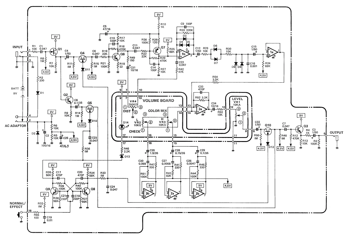
Firstly, here’s the Digitech DOD PDS-1550 schematic diagram that we’re going to be using. The guts of the pedal are on two pages, and the third page deals with the input and output jacks, power socket, and two stomp switches.
Let’s have a look at a block diagram of the whole pedal first, so we can orientate ourselves a bit.

After the input buffer, there are two channels, A and B. Channel A is the Metal Distortion channel, and is followed by a double-tracking delay and a complex tone control. Channel B is the Overdrive channel and is much simpler. Both channels are output through the parametric EQ and then an output buffer.
One footswitch on the pedal switches between channels A and B, and the other between the effect and the bypassed signal.
The switching is all done using FETs and the logic for the various options is pretty involved and generates quite a lot of circuitry, as you’ll have seen if you took a look at the schematics. I’m going to gloss over that for now.
Input Buffer
Ok, we warm up with a unity gain op-amp buffer.
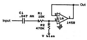
This is pretty standard stuff. R2 is a bit smaller than we might like to see, but 470K input impedance isn’t bad by the standards of its day. The value of C1 gives a roll-off below 10Hz, so we’re not losing any bass anywhere. The ‘1458 op-amp isn’t the greatest – basically a dual package with op-amps similar to the uA741.
If you’re wondering why there’s no input jack, it appears on a separate sheet and I didn’t copy it in here.
Channel A: Metal Distortion
Channel A is the complicated part of this pedal. We jump to page two of the schematic, and it gets a whole page to itself, whereas Channel B has to share with the power circuitry and all the switching logic.
First thing to say is that as mentioned earlier this circuit is practically identical to the schematic of the Boss HM-2 Heavy Metal pedal. Without knowing the exact timeline, I’m guessing Digitech were “inspired” by Boss rather than the other way around, but both are inspired by earlier pedals. We’ll come to that in a moment.
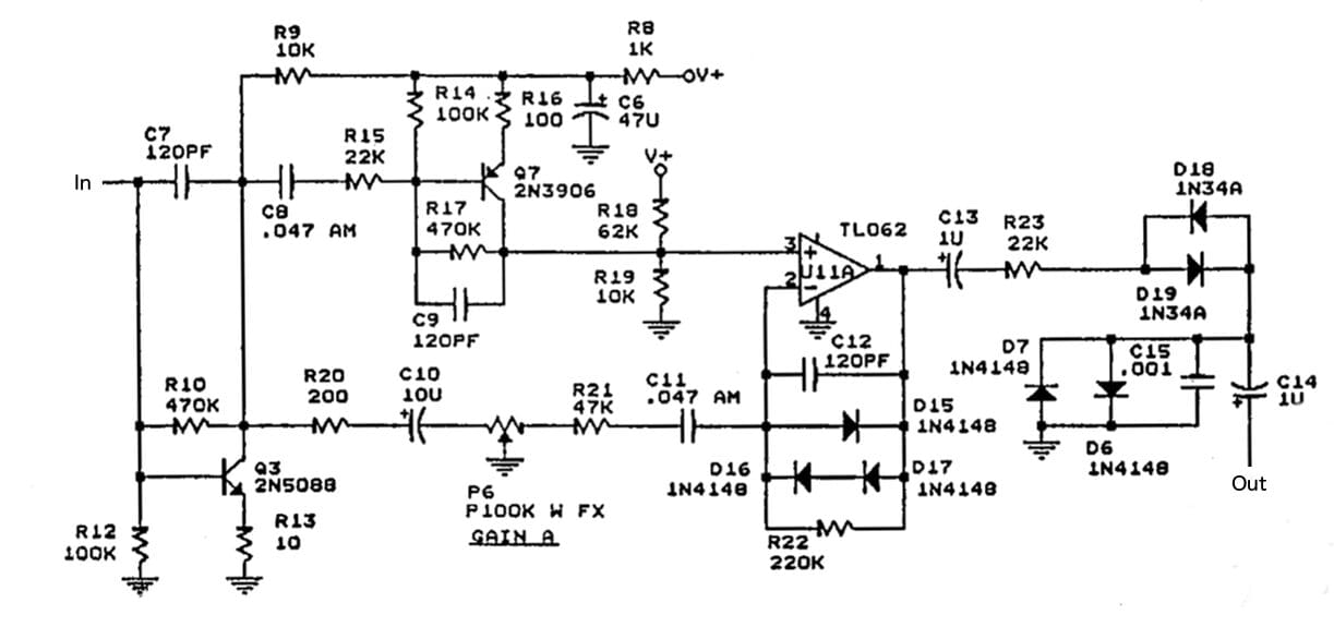
Let’s go through the distortion circuit a bit at a time. First let’s redraw the two transistor stages, with the second stage based around the PNP transistor Q7/2N3906 drawn the other way up. This makes it clear how similar these two stages really are.
First and Second Transistor Stages (Q3 and Q7)
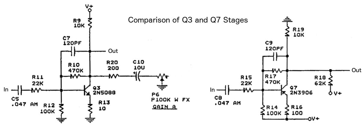
Ok, now let’s look at the circuit around Q3/2N5088. This is a gain stage exactly like the input of a Big Muff Pi or a Boss DS-1. The 120pF value is half the 250pF the DS-1 uses, and that is half the 470pF the Big Muff uses, so this version gains an octave or two octaves more high frequencies than those comparable circuits. The frequency response shaping components are chosen such that the whole of the guitar’s spectrum is allowed to pass. There’s no heavy shaping of the signal before we clip it here.
One of the potentially interesting things about this circuit is the way that both ends of the gain pot are used to alter two different parts of the circuit at once. So how do these changes play out?
For the first transistor stage, the variable gain pot has almost no effect until you are in the last 20th of the pots travel – e.g. values below 5K. Here we can see the frequency response for 10K, 5K, 1K, and 0K values of P6/Gain A.
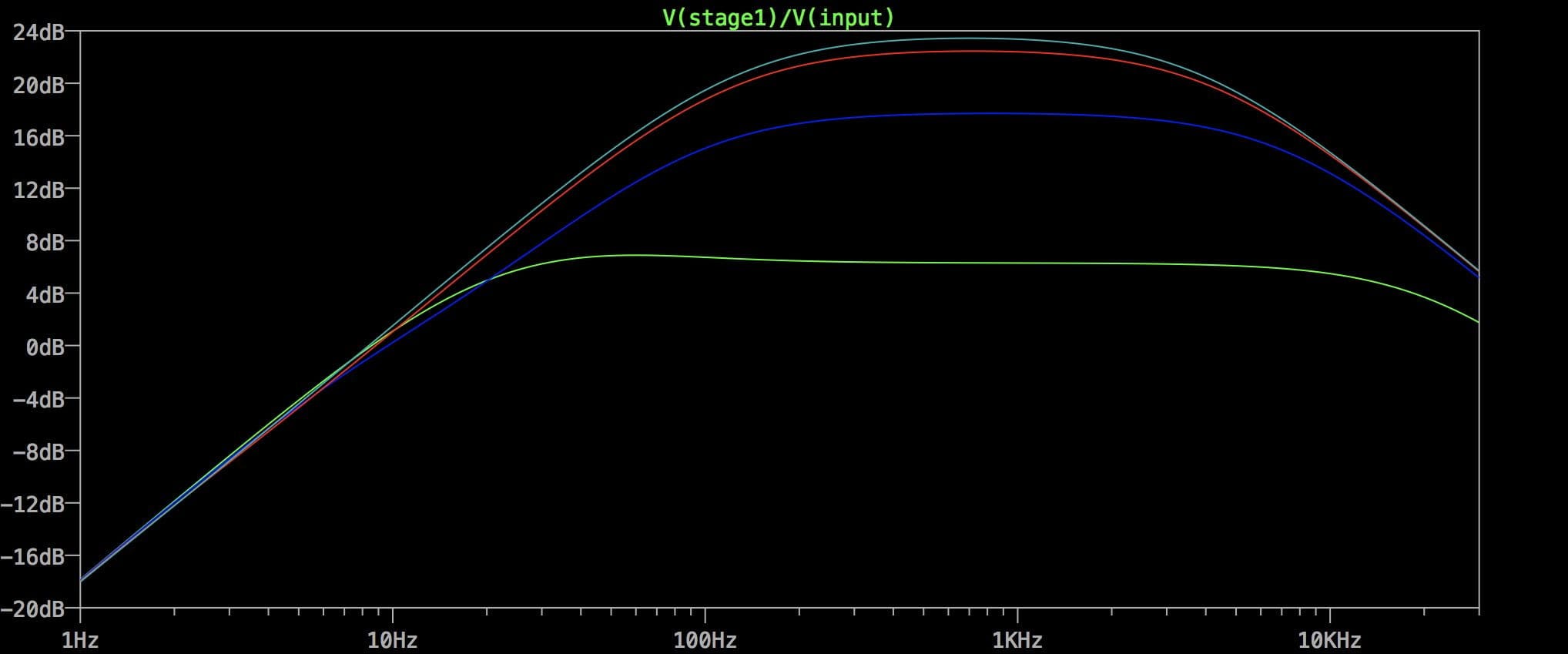
As you can see, only 1K and 0K actually change anything much. That makes this end of the pot almost pointless. We’ll see whether the other end does anything when we get to it. Basically the first transistor stage provides 24dB of boost regardless of pot setting. That’s a gain of x15.8, enough to amplify a 300mV input so that the transistor’s output is at 5Vpp.
One of the criticisms of the Boss HM-2 pedal is that its gain control does virtually nothing until the last moment. For me, this proves someone lifted this circuit from someone else – the chances of designing in exactly the same faults are tiny. If you’d designed this from scratch, you’d avoid this kind of problem. What’s amazing is that Boss released it in the condition they did. It’s a rare slip-up from the usually extremely reliable Boss engineers.
Right, so onto the second stage around Q7/2N3906. Having seen already how similar it is to the first stage, we’re not expecting hugely different results, so the frequency response should come as no surprise:
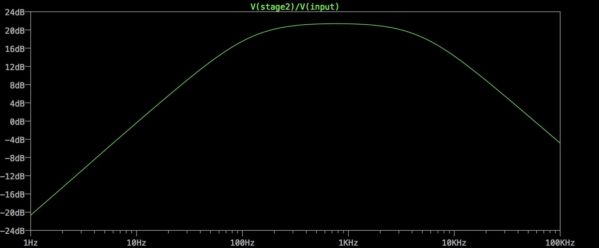
This stage doesn’t provide quite so much gain as the previous one, but 21dB is still a lot of gain, especially on top of what we’ve had already. We’ve now got 45dB of gain, x178. It’s no wonder it’s a chainsaw. And we’re only on stage 2.
Note that the 10K load resistor R19 is also used in association with R18 to tweak the bias point for the next op-amp stage.
Op-amp and clipping diodes
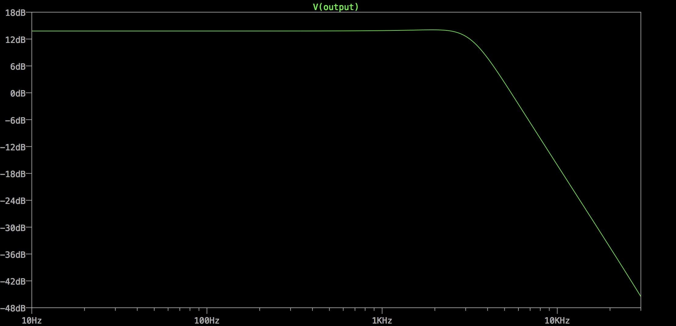
The op-amp stage is an non-inverting clipper stage, not hugely different from the TubeScreamer design. The gain varies from 2.5 to 5.7 (8dB to 15dB), so this has a lot less gain than previous stages. R22/220K and C12/120p give a rolloff above 6KHz which helps stop the clipping getting brittle.
From the op-amp we go out to another set of clipping diodes, but before we get there we’ve got a pair of 1N34 germanium diodes D18/D19. These are used as a simple noise gate, since they’re in series with the signal path and they only conduct once the voltage reaches a certain level, so they act as a noise gate threshold. They’ll also introduce a certain amount of unwanted crossover distortion, but since this is a distortion stage anyway, we probably won’t notice. Incidentally, the reason crossover distortion is rarely used deliberately in pedals is because it affects smaller signals worse than larger ones, which is typically the reverse of what we’re after.
After the series germanium diodes, we have a set of silicon clipping diodes to ground. R23/22K coupled with C15/1n gives a lowpass action at 7.2KHz, so it trims some treble without affecting any guitar notes.
The whole design is an extreme example of “gain staging”, where you build up a high gain sound in several steps. The first transistor probably won’t clip unless you feed it a pretty hot signal. The second transistor almost certainly will clip. The op-amp will definitely clip, and then the silicon diodes will clip the op-amp output again. So our original signal gets sliced and diced!
Double tracking Delay
This part of the circuit is an original Digitech addition. The HM-2 doesn’t have anything like this.
The delay circuit provides only a single repeat at a very short delay time, a “slapback” or “double tracking” effect. If it had a bit of modulation, it would almost be a chorus on a long setting.
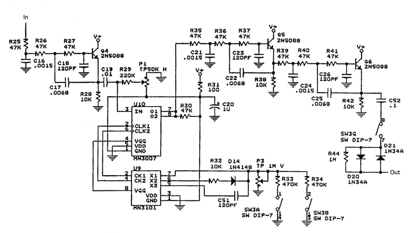
This is fairly straightforward, although it adds a lot of circuit. We can break it down into subsections to make it easier to manage.
There’s an pre-delay anti-aliasing filter based on Q4. This is a 3-pole (-18dB/Oct) filter. Cutoff is about 3.4KHz. They claim 4KHz bandwidth for the delay in the user manual, but 4KHz is the -6dB point, not the cutoff.
Then there’s the actual MN3007 BBD delay line itself, and its associated MN3101 clock circuit. These are PMOS devices which expect a negative supply, which explains why they’re wired with the supply pins “back to front” here. There’s a Delay Time knob (P3/1M) but amazingly you can only get at it by taking the back off the pedal – it’s a trimmer, not a control. There are also a couple of DIP switches which add resistors in parallel with the trimmer to change the delay time range. With both switches open, you can have up to 40msecs. With one switch shut, you have up to 20msecs. With both switches shut, you have up to 10msecs. That’s into a flanger range and will have interesting comb filtering effects on the sound, although without the feedback you’d expect on a flanger, they won’t be very pronounced. One mod I would definitely want to experiment with on this pedal would be to add a feedback control to the delay. Whether it sounds any good is an open question, but it would open up a lot of possibilities, especially in combination with the delay range switches.
Assuming the worst-case 40msec delay time, the clock frequency comes down to 12KHz. This is audible, even for most over-forties. This explains why they’ve chosen a 4KHz bandwidth – it’s a conservative one-third of the clock rate, which is typical for BBD circuits.
After the delay line come a pair of post-delay filters based on Q5 and Q6. These are both 3-pole filters, and are identical to the pre-delay filter we’ve already seen. Since there’s two of them, we’ve got -36dB/Oct of lowpass filtering after the delay. That’s a lot more than you commonly see, and will rid us of any clock noise much better than most.
These are followed by a DIP switch to turn the delay on or off and a pair of germanium diodes doing the same “noise gate” trick we saw on the distortion stage. When they’re not conducting, the resistor R44/1M acts as the only path, so BBD noise is heavily attenuated.
Delay Mixer
After the delay, there’s a simple mixer stage to recombine the straight distortion sound and the delayed version. This is a normal inverting op-amp mixer. Both the straight and the delayed signals are given equal weight. The undelayed distortion signal comes in via R43, and the delayed signal via R45, both 62K.
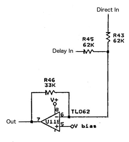
Note that the feedback resistor R46/33K is half the value of the input resistors, so the overall level stays broadly the same (twice the input, but at half the level).
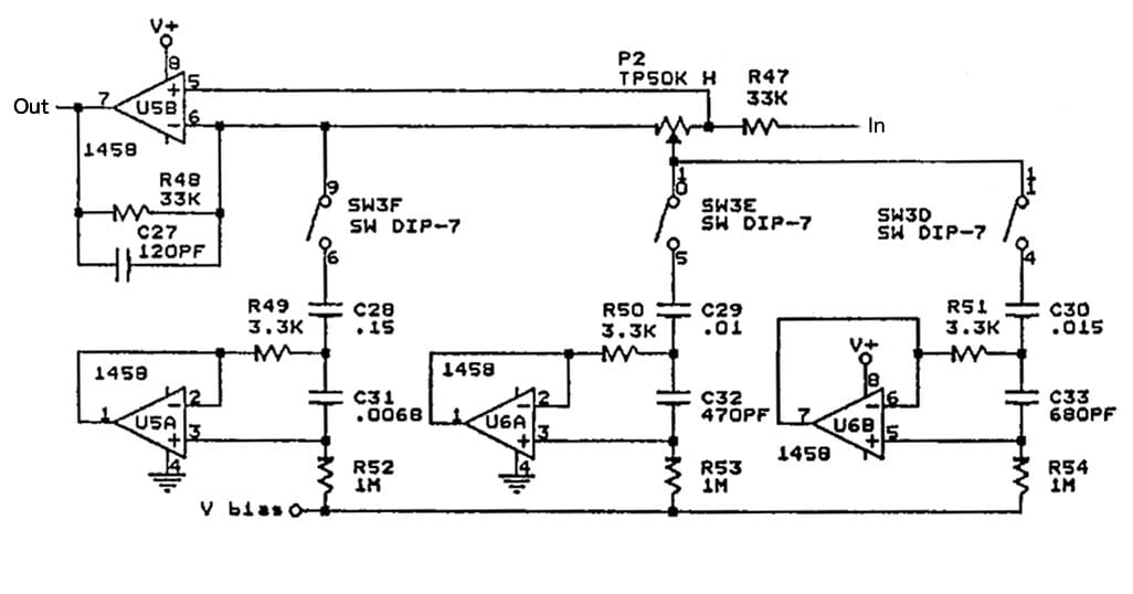
Tone shaping filters
The Metal Distortion channel doesn’t just get the output EQ like the Overdrive channel. Before it gets there, it passes through an extra set of tone shaping filters. These are gyrator based, and the effect of the two higher controls is altered by a global cut/boost control. Again, this is a trimmer that you can only get at with the back of the pedal off. You could do a lot to this thing by drilling more holes in the box and putting all the controls on the front – if you can find space. Not only that, but there are three gyrators giving different frequency peaks, and each is individually switchable in or out with a DIP switch.
The Boss HM-2 uses the same three-gyrator arrangement, except that the low frequency gyrator has a control instead of just a switch. But since everyone reckons the controls are rubbish and the only setting worth having is maximum boost on both, a switch is enough. It’s also worth pointing out that although the PDS-1550 uses different component values, the resulting frequency response is extremely similar. It’s almost like someone was trying to get the same result without just copying the circuit.
Starting on the left, we’ve got a gyrator with a frequency of 87Hz, and a Q of 3.7, which is a bit over a third of an octave. That’s very marginally less than a typical graphic EQ band, which use a third of an octave, or a Q of 4.3. All the gyrators share this same bandwidth. The central gyrator has a frequency of 1278Hz. Finally, on the right we have 868Hz.
The gyrator on the left is quite different in frequency to the other two. It’s a deep bass peak, and it can only be switched on or off. It’s described in the user manual as a “lo boost” and that’s pretty much it. The others are broadly a lower-mid and an upper-mid control, around the commonly used midpoint of 1KHz. Since that 1KHz point is pretty high for guitar, maybe it’s better to think of them as “mid” and “high-mid”.
Let’s compare this tone shaping section with the Boss HM-2’s “Colour mix” controls:
| Low | Low Mid | High Mid | ||||
|---|---|---|---|---|---|---|
| Freq | Q | Freq | Q | Freq | Q | |
| Digitech PDS-1550 | 87Hz | 3.7 | 868Hz | 3.7 | 1278Hz | 3.7 |
| Boss HM-2 | 87Hz | 3.7 | 958Hz | 3.4 | 1278Hz | 3.7 |
As you can see, it’s basically identical. The only part that changes is that Digitech have the low mid peak set slightly lower (a shade over a semitone), but with a tiny bit more Q. This is a very small difference.
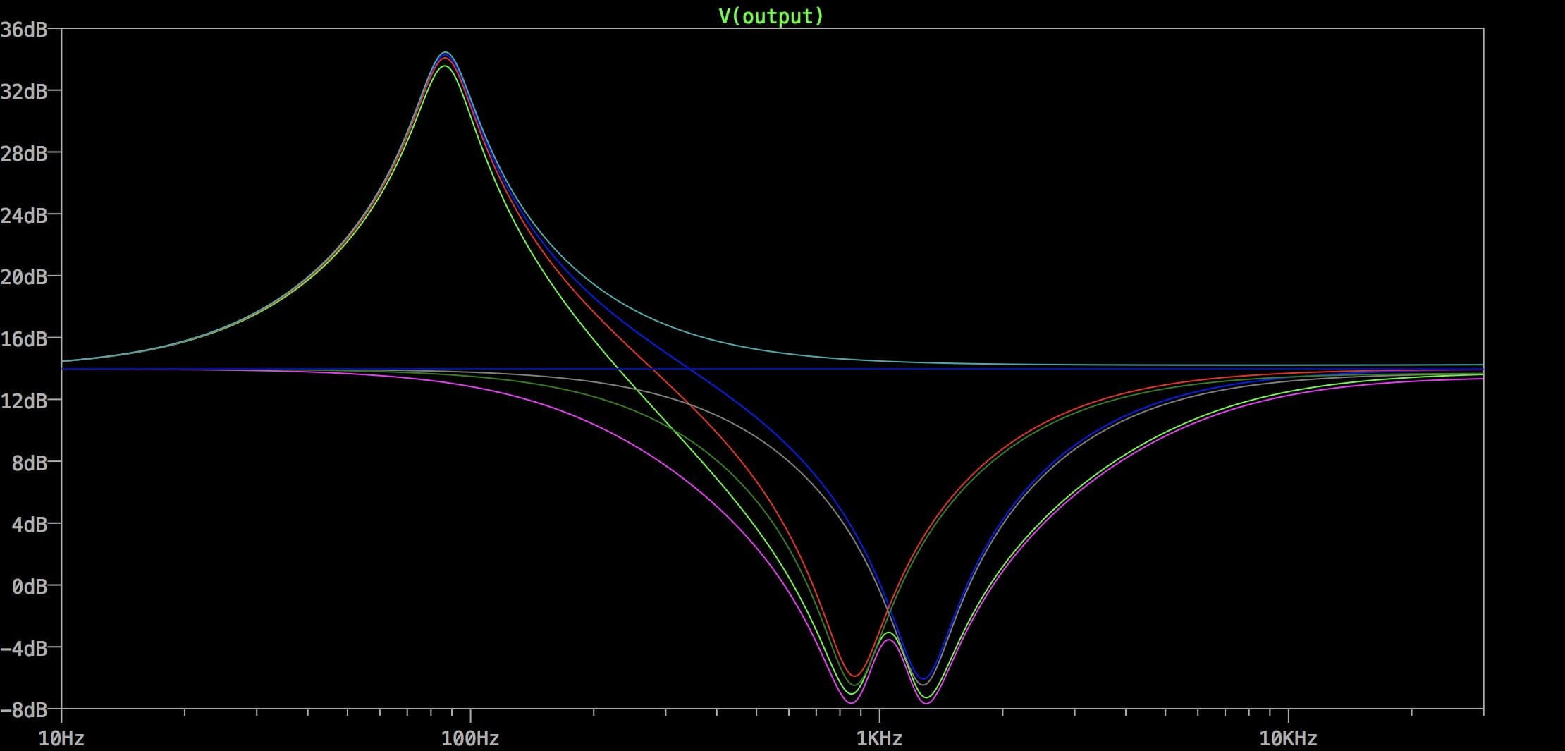
So what could you do with it? Unlike the Boss, in the Digitech pedal you’ve got eight combinations of switches, including the “all off” setting which doesn’t change anything. Here’s what they produce with the trimmer at the “maximum boost” position. The classic “Swedish chainsaw” sound is this with all three switches on.
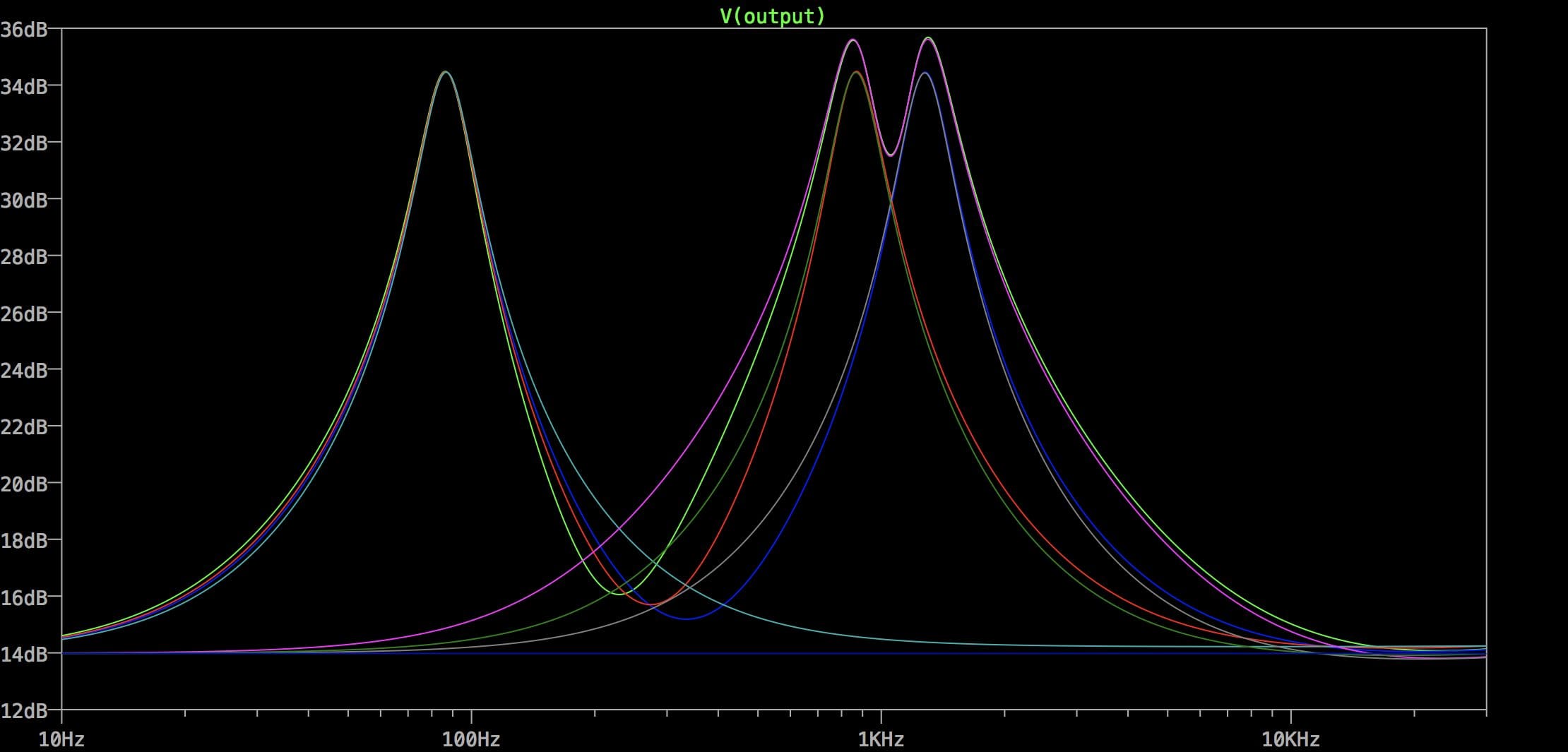
Of course, for the two peaks on the right, you don’t have to have it quite so drastic. You can tweak the trimmer. For the Lo-boost, you don’t get any choice – lots of boost, or nothing.
Let’s have a look with the trimmer at the opposite “maximum cut” position. “Lo-boost” is still a low boost. The HM-2 has a cut/boost control for the low peak too, so it can produce a “double notch” response that we can’t get on the PDS-1550. But since no-one seems to like such a setting, maybe it’s not a big loss.
Note that C27/120pF doesn’t affect the audio frequency response. It gives a roll-off above 40KHz, which prevents ultrasonic oscillations and radio interference and so on, but won’t do anything to our audio.
From the tone shaping filters, Channel A goes out to the Parametric EQ and the output buffer like Channel B. But first let’s take a look at Channel B.
Channel B: Overdrive
Channel B is a basic overdrive channel. It’s rather similar to a Tubescreamer at first glance, and probably at second look too, but we’ll note the differences as we come to them.
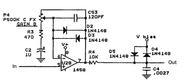
The values aren’t exactly like a Tube screamer, but it’s similar in structure with the clipping diodes in the feedback loop of a non-inverting op-amp. One difference is the way they’ve organised the Gain control (more like a Boss DS-1), and the fact it has no series resistor inside the the feedback loop. This has big consequences. At minimum, the gain drops to one, unlike the Tubescreamer which has a 51K resistor in series with the 500K pot ensuring there’s a gain of x12 even at the minimum setting. This pedal cleans up a lot more. Another difference is the R3/470R resistor. The Tubescreamer use 4K7 in this position. Reducing the value of that resistor by a factor of ten increases the gain by a factor of ten! At the maximum setting, the gain is (500K/470R)+1, which is x1065! That’s a lot of gain for a Tubescreamer-type circuit, and way more than the x118 that the original manages. So they’ve taken the same basic circuit and run away with it.
The way the pot is arranged also means that the resistance that C2 sees varies with the gain since it is R3 + some portion of P4. At minimum gain that makes a highpass at around 0.3Hz – effectively passing everything except DC. At maximum gain, we get only the value of R3, which gives us a highpass action 338Hz. This is still an octave lower than the Tubescreamer which uses a fixed 720Hz, but should be enough to stop the sound getting muddy at higher settings. In a similar way, the amount of topcut provided by the 120pF capacitor C53 also varies with the gain. It has a lowpass cutoff of 2.7KHz at maximum gain, and lets more treble through as you lower the gain. The effect of this will be to tame the massive distortion a bit at higher gain settings, which can hardly be a bad thing given the gain available.
However, that’s not all that’s going on. Unlike the Tubescreamer, we have a second set of clipping diodes. The clipping is softened a little by the series 10K resistor R4, and the result is lowpass filtered by R4/C4 at 5.9KHz.
There’s no separate tone shaping for Channel A. We go straight to the Parametric EQ.
Parametric EQ
I have to come clean and admit that this EQ was one of my main reasons for wanting to study this pedal. It provides a sweepable cut/boost control, and even offers variable Q (called “Octaves” on the pedal) – it’s a true one-band parametric EQ. Unlike the the vast majority of cut/boost EQs or sweepable mid controls, it doesn’t use gyrators of any type. Unlike the Boss MT-2 Metalzone sweepable mid control, it doesn’t use a Wien bridge circuit either. It uses a state variable filter (SVF), but not any old basic op-amp based SVF, rather a fully current-controlled SVF based on the LM13600 dual OTA chip. The reason for this is that a SVF requires the simultaneous adjustment of two resistances to alter its frequency. Digitech/DOD were apparently trying to avoid using a dual-gang pot, since the current control allows them to alter both sections with a single-gang pot wired as a simple variable resistor.
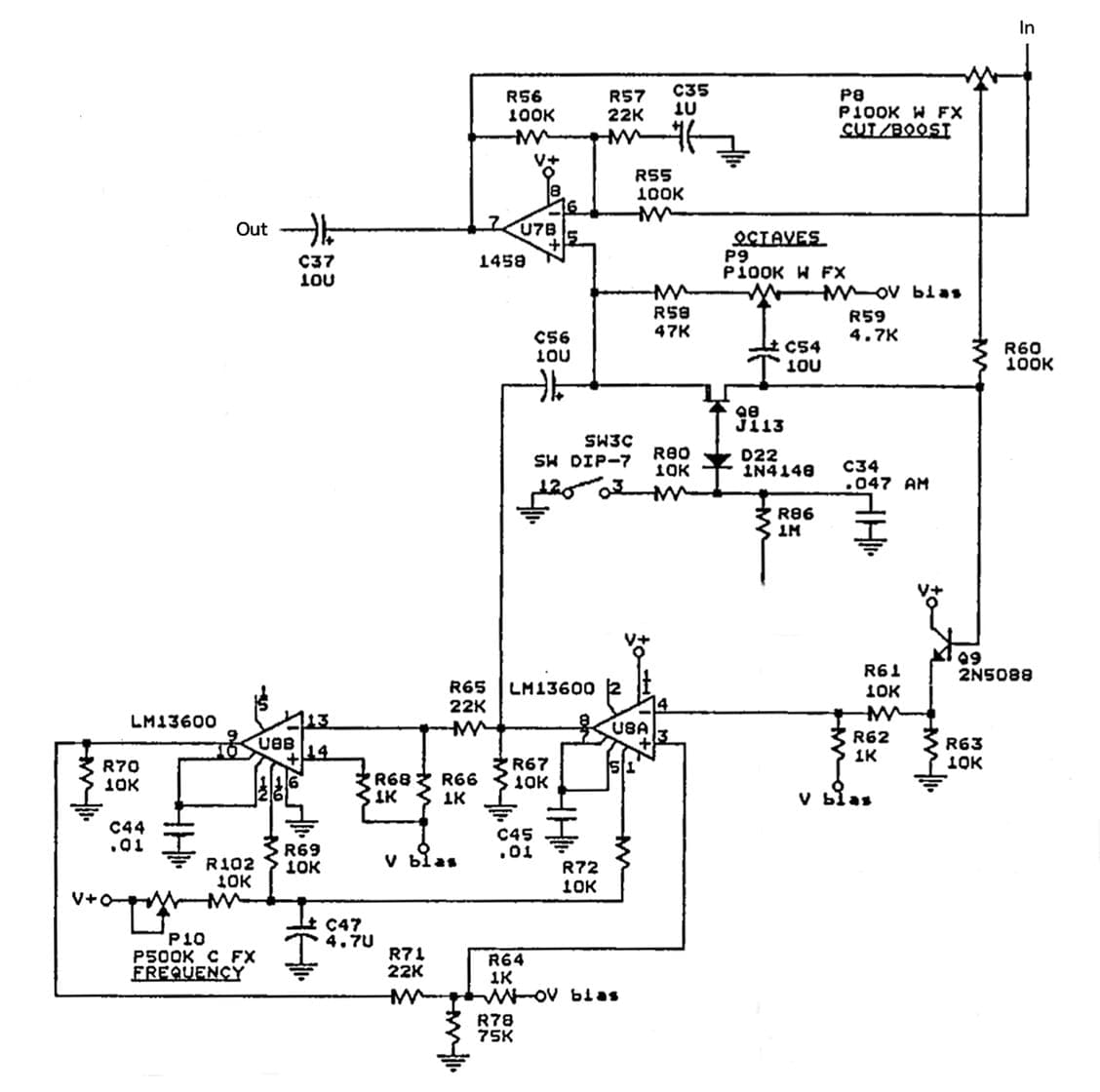
This circuit is itself made of several distinct blocks. At the top, there’s a differential op-amp U7B being used to produce the cut/boost by either adding or taking away the bandpass signal from the SVF. On the right, there’s a simple transistor buffer Q9 mixing signals going into the SVF. At the bottom we’ve got the SVF, based on the two OTAs in the LM13600. This is a two-stage filter, so it’s 12dB/Oct. The output from the first stage U8A is a bandpass output, and that’s the one used here (via C56/10u). The output from the second stage U8B is lowpass and is only used for feedback in this circuit. You could completely mess with the parametric EQ by using the lowpass output from Pin 9 of the LM13600 instead.
The Cut/Boost control is pretty extreme, offering +/-20dB. The Frequency control is similarly powerful, with a range from 100Hz to 3700Hz. That’s well down into the bass range, and well up above what we’d normally think of as “mids”. The “Octaves” control changes how wide the peak that we’re playing with is. It can be as wide as 1.6 octaves, or as sharp as 0.1 octaves (pretty much a single note – watch for feedback when you hit that one!). In terms of “Q”, that’s 0.86 to 14.4, which is a very high Q for an EQ.
There a FET Q8 and a DIP Switch in the middle of this circuit which allow the EQ to be turned off. This is used to optionally disable the EQ for Channel B, the Metal Distortion channel. Set up like this, the Metal distortion has its tone shaping circuit, and the Overdrive has the parametric EQ. This perhaps makes more sense of the dual channel structure.
That’s just about it. From here, we go out to the output buffer.
Output buffer
This is another simple unity gain op-amp stage. Absolutely standard building-block stuff. R76/1K limits the current if someone shorts the output, and also helps the op-amp drive a capacitive load (like a long guitar cable) without oscillation. C39/4u7 is the DC blocking cap that separates us from the 4.5V bias voltage we’ve been carrying around until now, and R77/100K allows any charge on that cap to leak away to ground to prevent pops.
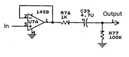
You could do worse than put one of these on the end of all your pedals, although you might like to use a better amp than the rather dated 1458.
Conclusions
Throughout this article, I’ve been drawing attention to how similar parts of the circuit are to other famous pedals. This is not to criticise Digitech/DOD’s work in any way. All good pedals draw on what has gone before them for inspiration, and there aren’t many original analog audio circuits left in the world to build anyway – everything has been invented already, and it’s up to us to combine it in new ways. It seems to me that is what Digitech were trying to do here. They took a heavy metal distortion and a overdrive design, and put them in one box. They added a delay to the Metal channel, and they put a powerful parametric EQ on the output to sculpt the sound further. Perhaps none of the elements are remarkable, but I’m damn sure you’ve never seen a pedal like this before, I swear. Anywhere.
So is it any good? What’s it good for?
What, aside from being a cheaper version of the Swedish Chainsaw sound, with added delay and EQ? That’s not enough for you?
Given the amount there is going on, I’d expect that pretty much everyone could get one sound that they could use out of it, even if it never becomes your favourite pedal. The two channels are sufficiently different that I can’t see anyone really liking both of them. I’d guess you’ll gravitate to one or the other. Carlos Santana wasn’t really a Death Metal kind of guy, was he? So going from his TS-808 drive tone to screaming mayhem for solos? Maybe not. Or vice-versa; doom-laden guitars with bone-crushing weight to a bluesy crunch for lighter segments? Seems equally unlikely.
There are some (ok, many) odd design choices, like using the Parametric EQ for both channels although they did allow you to defeat that decision, or using all the complexity of the delay line circuit and it’s associated filters for just a single echo. That could have been shared by both channels, or we could have had an LFO to give us optional chorus sounds (hey, it was the Eighties…Chorus was bigger than Madonna’s hair.). Better still would have been some actual programmability to give us more control over all those knobs and possible sounds, even if that was just an alternate set of knobs set up as trimmers inside the unit so you could switch between the front panel sound and a “stored preset” sound on the trimmers. As it is, it’s a weird mixture of preset/trimmable and front panel elements.
All in all, it’s a quirky pedal with some interesting technical elements and several odd design decisions. While I don’t think it was ever going to become a classic, there’s definitely some things here we can learn from.
If you’ve got one, or had one once, drop us a line in the comments and tell us what you think of it. I’d be interested to hear.
Credits
Thanks are due to the helpful people over on the DIYStompboxes forum, who offered their contributions in the thread where I asked questions about it. Teemuk takes the credit for spotting the similarity between the PDS-1550 and the HM-2.
I love the second channel. Should I get a tube screamer, or is there something you’d recommend?
Thanks
Steve
Hi Steve,
I think there differences from the standard tube screamer circuit are significant enough that you’d probably find the TS wouldn’t really do it for you. This PDS circuit has more gain, changes the frequency response, and includes a second set of hard clipping diodes, so although it shares some similarities, it’s not a Tubescreamer. It wouldn’t be a hard circuit to build up on veroboard though, if you wanted to have a stand-alone version.
Thank you for this very informative review.
I’ve had this pedal since the 80’s and in a studio situation I’ve and great success getting a variety of tones out of it.
Bass is my main instrument but I play and record a lot of guitar !
I played bass in a grunge band in the ’90s and used the A channel as a massive fuzz mayhem and the B channel as clean boost. I had it serviced rom Digitech in 95 and they replaced all pots and whatnot. Very cool, but I’ve never been real happy with it for guitar. It’s been in storage for 20 years and I just fired it up. Pots are OK, but there’s some crackle and I think it may be capacitors. I wonder if it will clear up when I find a power adapter with suitable polarity and let it sit and get used to electrons flowing through it again. If it cleans up I may put it up for sale…
Hi Tom, thank you for this really excellent dissection of the pedal. I just picked one of these up and would like to use an external power supply instead of the battery, but it comes with a non-standard jack. Looking at the last page of the linked schematics, it seems that this is a ground to chassis setup instead of the more commonly used 9V+ to chassis that you find on most pedals.
So if I read this correctly, all I need to do is wire up an adapter with a hollow plug receptacle to a 3mm mono plug and connect the outside lead of the hollow plug to the tip of the plug (and the inside to the ring of the plug), right?
I don’t agree that +9V to chassis is “more common”. You do see it occasionally, but the large majority of pedals connect the jack sleeves and chassis to the battery -ve connection. The PDS-1550 does this too. Since it uses a jack for its power input, that implies that the jack sleeve needs to be negative and the tip positive – the reverse of the usual “Boss standard” centre-negative convention.
If you’re going to build an adaptor, you’ve got it exactly right: The hollow 2.1mm DC plug needs the outside connected to the tip of the jack, and the negative centre connected to the jack sleeve.
Personally, I’d buy a insulated plastic 2.1 DC socket and drill a bigger hole on the PDS1550 and just replace the non-standard jack with a standard pedal power input so it was the same as everything else on the board. Is there space inside for such a socket?
(This sort of thing: DC Jack on Banzai Music).
Hi Tom, I hope you’re still around. I am interested in the power supply. I got the pedal but she got the power supply in the divorce. Lol. True but sad. Anyway, The box has a 3.5mm , TS, 1/8th” jack connector. Is it corect your saying the tip is neg and the sleeve is positive? Thanks in advance.
Did I say that?!? No, on the original DOD 1/8″ jack, tip is positive, sleeve is ground.
But honestly, pull it out and put a Boss-style power socket on it instead so it’s the same as everything else in the world.
I’ve had this pedal for 30 years. The Channel B Overdrive is usable and sounds great for rock and blues in all gain positions.. I like to use it to add grit at say 9 o’clock position and push it with a tube screamer for blues lead. Even at unity gain is so nice to have it ON to use the EQ… Channel A
metal tones can be tamed with the internal dip-switches and hi filter trimmer to get a great bridge Humbucker distortion lead tone for solos with a lot of sustain; the included delay line is key to its sound. The Parametric EQ by itself is great and very responsive with variable Q!!. Choice of 2 sounds plus the EQ in a box made me not need another overdrive box other than the essential Tubescreamer in series prior to the PDS-1550
Thanks for the comment. Nice to hear some positive feedback about this pedal!
Tengo el pedal Digitech PDS1550 y quisiera modificar el canal B , para que con la ganancia en 0 , no baje tanto el volumen, que componentes podría modificar?? Muchisimas gracias !!
Tienes distorsión con a ganancia en zero? En este posición la ganancia total debe ser unidad, y no debe bajar el volumen. Entonces, solo sera bajado el volumen si los diodos D4/D5 están cortando la onda. Pero tambien hay el EQ paramétrico que puede modificar el volumen mucho. Si encontras que el volumen es muchos mas bajo que unidad en el Canal B, puede que hay un falto.
(Perdona mi español. ¡No tengo muchos opportunidades de practicar!)
I bought one of these off a friend in high school and loved it. Gigged and recorded with it. I bought a 2nd one later but it didn’t seem to have the same tone. The circuit boards are pretty different, one clearly being a machine created pcb and the other looking more “hand drawn”. In any case I did something terrible and cannibalized a couple parts from both. I’d like to get them both running again but I’d like to do a couple things:
I need a replacement long pin pot with the split knurled shaft. Can’t seem to find them.
I’d like to instal push button stomp switches for the bypass and A/B instead of the touch pads. I’ve had those fail on these units and on an RP-7 Valve I used.
I’d also like to change the power input to a boss style.
I can solder with the best of them but I’m pretty ignorant about electronic schematics.
Any input or help would be awesome!
Thanks!
Interesting to hear about the two versions. I haven’t seen any sign of differences in any of the documentation, but it’s not unlikely. Digitech/DOD recycled a lot of their circuits, sometimes tweaking, sometimes releasing the same thing with a new name to catch a fad.
Swapping the Bypass and A/B switches for stompswitches is pretty involved – check the schematic. If the pushbuttons have broken, I’d be inclined to simply replace them – they’re just simple keyboard switches, so they’re not expensive or hard to find.
If you do decide to go for footswitches, you basically need to pull out all the FETs that do the electronic switching and replace those connections with the footswitches. But watch out because some turn on when others turn off!
Maybe it’s a good idea to post a photo of the pedal in your article.
Vivek
There used to be one. We recently changed the theme on the website, and it disappeared, so I’ve put it back. Thanks for the heads-up!
THANKS A LOT . I love My PDS1550, but trim thing still a doubt. 1 hi cut boost ok , simple. But 1M and 2k2 are delay ones? but the trouble is the other one that realy get some IC hot almost burning and I don`t know what I should do to keep it not overloaded.
The delay got the same trim pots from de FX90 delay, cousins? https://www.doktorsewage.com/hot-rod-dod-mod-fx90-analog-delay/?unapproved=26108&moderation-hash=06c4a7823752e98516747985a2558505#comment-26108
Getting really hot doesn’t sound good. That sounds like a fault.
The 1M pot on the FX90 is pretty similar to the PDS1550, but on the FX90 there’s an actual Delay Time control in parallel, so the trim sets the *maximum* delay time. Here it just sets the delay time, since there is no knob.
I can’t find a 2K2 trimmer. Where should I be looking?
My PDS1550 is currently not working. I’ve only used a 9 volt battery since I don’t have a adapter. The pedal fires up but it seems to be stuck in bypass as the knobs or switches have no effect. I can switch between A and B fine. The lights continually flash on and off. Any help would be graciously appreciated! Thank you!
I recommend starting a debug thread on DIYStompboxes.com. There’s a load of useful people there who will be able to help (and me too!). From the symptoms it sounds like the switching logic has gone funny.
#1 – this article is phenomenal!!! Yeah, its about the PDS1550, but its a semester or two of college-level info on audio circuit design in one url. I’m going to have to dive into whatever else you have going on here.
#2 – Have several PDS units from THIS PDS1550 ( my first purchase at 15 ), the coveted PDS8000 ( that set me back like $300 in ~91 as my second purchase ), then dropped an entire summer of dishwashing/bussing at ~$700+ on the Legend II, & somehow ending up with the PDS3500 when I really didn’t know WTF MIDI really was. I just shagged a PDS2700 out of nastalgia ( yes, suffering from severe GAS[gear acquisition] dysfunction ) Which leads me to my question:
Just broke out my PDS8000 after a recent home-studio “set all my sh*t up, wired up, ready to plug-n-play once & for all” session & the Regen pot is [all or nothing] with a nanometer twitch & wondering if there’s a part#/source you might recommend?
Any good suppliers one can recommend for general audio parts? While I’m going through this process I’m working through several decades of antiques & stuff that I somehow ended up with from an ART SGXExpress with output issues, to GSP-2101 with failing data encoder, and a sick amount of other equipment I’d like to fetch parts for before the WEF kills off all the suppliers/supplies.
Fullcompass has stuff for their more modern lines, but amprepairparts looks promising.. I checked this 1550 schematic & saw 100K/50K pots – intuition tells me Digitech is likely to use common parts across their line – either due to similar design or for cost reduction….
Anyway, again AMAZING and ACCESSIBLE analysis on this PDS1550 and its somewhat serendipity as I just got a MAC to run Korg’s SynthEdit for the OASYS PCI that allows one to create custom synths using their card, so the fundamentals you covered are PRICELESS.
THX,
SILOSIX
Where are you based? I could probably come up with a few urls you could check out for suppliers, but EU ones aren’t much good if you’re in the USA, and vice-versa!
‘FEMA Region #6’ in Austin, TX, thx!
Well, in the USA, Small Bear is the one! And now they’re back! (the original owner retired, and it looked like it was going to close down, but it’s been bought by the people behind SynthCube).
https://smallbear-electronics.mybigcommerce.com
Their site is having a bit of a transitional period at the moment, but it’s up and running and they’ll get it sorted out in time, I’m sure.
For cheap stuff from the far east, Tayda comes highly recommended by many:
https://www.taydaelectronics.com
HTH
sweet! thx so much Tom!
Here’s the mag link I spoke of… just pushed it up:
https://archive.org/details/polyphony-1979-sept-oct
haha…I hit this article kinda late at night.. just went to your home page… no small irony I’m asking a parts site where to get parts…
What a kicka$$ site brother! I used to jam out with a cat that was like 20 yrs my senior & had those PAiA kits all over the place, he – like myself – was an archivist with a serious itch & he gave me some circuit & speaker designs[from 1998 dancetech.com]. I’ll have to dig them out, scan & give you a link.. I think you’d be a perfect curator..
I have an issue of Polyphony from 1979 & 3-hole sheets[mixer, reverb, tone control, and preamp stage & noise gate ] with PCBs & parts list. Probably lowbrow-level stuff for you, but might be interesting – if only for nostalgia.
something like this: https://archive.org/details/synthmanual_2720-5_Control_Oscillator_Noise_Source_builders_guide/mode/2up
I bought one of these when they were selling new. I never really liked the A distortion, I do like the channel B and especially the parametric scoop control, that is why I bought another one after the first one died. I never used the delay much as I had a delay pedal, the 40ms setting seemed annoying. I didn’t know till this article it was an analog delay (seeing as the company is called “Digitech”). I was looking for the schematic as I may try to build one with digital resistors and switches so I can call up “patches” rather than tweak knobs and unscrew the back. Thanks for the article it provides a lot of insight into the pedal.
For what it’s worth, I used to have the Boss Digital Metalizer and it also had a short delay with 3 settings, along with 2 chorus settings. I really liked how the longest delay (probably also 40ish msecs) fattened up the sound. Recently I tried the same with a PT2399 and your hard bargain distortion but I haven’t gotten around completing/finalizing it. Still on my list though 😀
I had one of these in the late 80s to early 90s for my bass rig. It was my favorite bass distortion, largely because of the PEQ. However, it did not stand up to the rigors of the road and got pretty flakey after 4 or 5 years. The switches didn’t switch reliably and the pots felt like they were coming apart on the inside (to be fair, it did get a lot of abuse). I recently found another for a good price. I was always surprised that I didn’t see more bass players using it.
Hey Guys!!, some alternative in power supply? Maybe in Amazon?
Recently I have been trying to find some power supply with no success to my pedal 2730 Hot Box Digitech.
The best thing to do is to buy a plastic-bodied 2.1mm DC socket and then take out the 3.5mm jack, drill the hole out a bit, and fit the other. Then you have have a Digitech PDS that can use the same power supply as every other pedal in the world :).
Remember that the Digitech jack is tip=+ve, but the standard Boss 2.1mm socket is tip=-ve. That’s why the DC socket has to be plastic, the outside is +ve and would short to the In/Out jack ground if it wasn’t.
Excellent article. I love the HM-2 and I love Tubescreamers. What I don’t get about this pedal is how the switches work, and I don’t quite follow the manual too well.
If I wanted the “All controls dimed” sound of an HM-2 and I wanted a Tubescreamer with a parametric tone control, what DIP and trim pot settings would I select? Both your write up and the manual say DIP 3 is for disabling the parametric EQ on Distortion B, but your article says B is the Metal side, where the manual says B is the overdrive side.
Honestly, I might have got that the wrong way around, I’m not sure. I was probably more sure back then when I did the article, but looking at it now, I got lost in the topsy-turvy logic of the flip-flop and the FETs, so I’m not sure.
Checking the Schematic, it does look like A is the Metal side, B is the Overdrive. The control marked “Level A” definitely follows the Metal side. Sorry about that.
Tenho um PDS2730 Hot Box e gosto bastante da distorção dele. Gostaria de saber se a distorção é parecida com esta e se consigo um esquema elétrico para fazer a manutenção.
Não parece haver um esquema disponível na internet, por isso é difícil dizer se é semelhante.