
 The Jupiter 4 was Roland’s first polysynth in 1979. Given that the Prophet 5 had been released the previous year, Roland were definitely playing catch-up, and the design looks notably less “modern” than Sequential’s game-changing instrument. Nonetheless, the Jupiter 4 is well thought of and sounds great, with a character of its own. It’s the quirkiness of it that makes it interesting. One key part of that quirkiness is its unusual oscillator design and the “close, but not quite” waveforms that it creates, so that’s what I’d like to take a look at today.
Jupiter 4 oscillator schematic
The oscillator design looks like this. As you can see, it’s vastly over-complicated! Compared to the early Prophet’s SSM2030 oscillator chips, it looks truly medieval.
I’ve marked this up into its broad functional blocks. Now, there’s a hell of a lot of stuff here, and there’s no way I want to build a VCO with even half this many parts, so I’m not going to look closely at everything. There’s only a few parts that create the unusal waveshapes the Jupiter 4 is noted for, so I’ll focus on those. With no further ado…
The less interesting parts
CV Mixer
 This is a simple op-amp CV mixer. It combines two control voltage inputs through R1 and R2, along with a trimmer from the exponential convertor.
Exponential converter
 This too is a typical design. There’s a lot you could say – exponential convertors probably deserve an article of their own. This one uses the uA726 matched transistor pair. This device included on-chip heating to keep the temperature stable (it gets hot). That was one successful 1970’s strategy for eliminating temperate-dependent pitch variations – just keep everything at a fixed temperature! And since you didn’t know how hot the outside world was going to be, it needed to be reliably hotter than that, so 40-50C typically. Positively tropical. Or Mumbai in summer? Arabian desert? I’m not sure.
Oscillator
 The actual oscillator is the sort of thing you see more commonly in digital circuits as a clock. It’s based on 4069 inverter sections. Incidentally, the Boss BF-1 Flanger pedal uses pretty much exactly the same design, although there it’s built with 4011 NANDs wired as inverters instead of actual inverters. This is something highly unusual amongst the usual ramp-core and triangle-core oscillators. It’s essentially a “Pulse core” oscillator. That choice lead to the strange waveshaping that follows it, and makes the Jupiter 4 oscillator a direct precursor to the later Roland DCO design. You can see many of the same ideas being developed here in a fully-analogue oscillator.
A detail that I don’t get about this design is why it uses the exponential convertor current to feed an intgerator (IC5b) which then feeds another current mirror! Why couldn’t we connect the expo convertor directly at Q2’s collector and save all those parts? They must have had a reason, but I haven’t been able to fathom it yet.
One final thing to notice is that the oscillator runs at least an octave higher than the final output pitch, since the output is divided down before it is used.
Pulse shaper
 This is a simple 555 monostable circuit, used here to provide fixed-length pulses. The R13/20K and C5/1n values give a calculated pulse width of 22usecs. That’s short enough that there’s no danger of the pulses “overlapping” for any audio frequency. The significant thing about the output from the 555 is that because the pulse width is fixed, the amount of time the pulse spends high is directly proportional to the frequency. This allows the following Frequency-to-Voltage stage to work effectively.
The interesting parts
Frequency-to-voltage converter
 The Frequency-to-voltage stage takes the pulse output from the 555 and turns it into a voltage representing the frequency. It’s basically just an RC lowpass filter and does this by smoothing the pulses into a DC level using cap C6. The more time the pulse input spends high, the higher the DC level will go. That’s why it’s crucial the 555 output is a fixed width – it ensures that the high time is proportional to the frequency, and therefore that the DC level is also proportional to the frequency.
Here’s what the output looks like for a 250Hz input. This would be a note about one octave below Middle C, since the oscillator runs an octave higher than the output pitch. As you can see, the ripple is pretty horrendous for low notes like these.
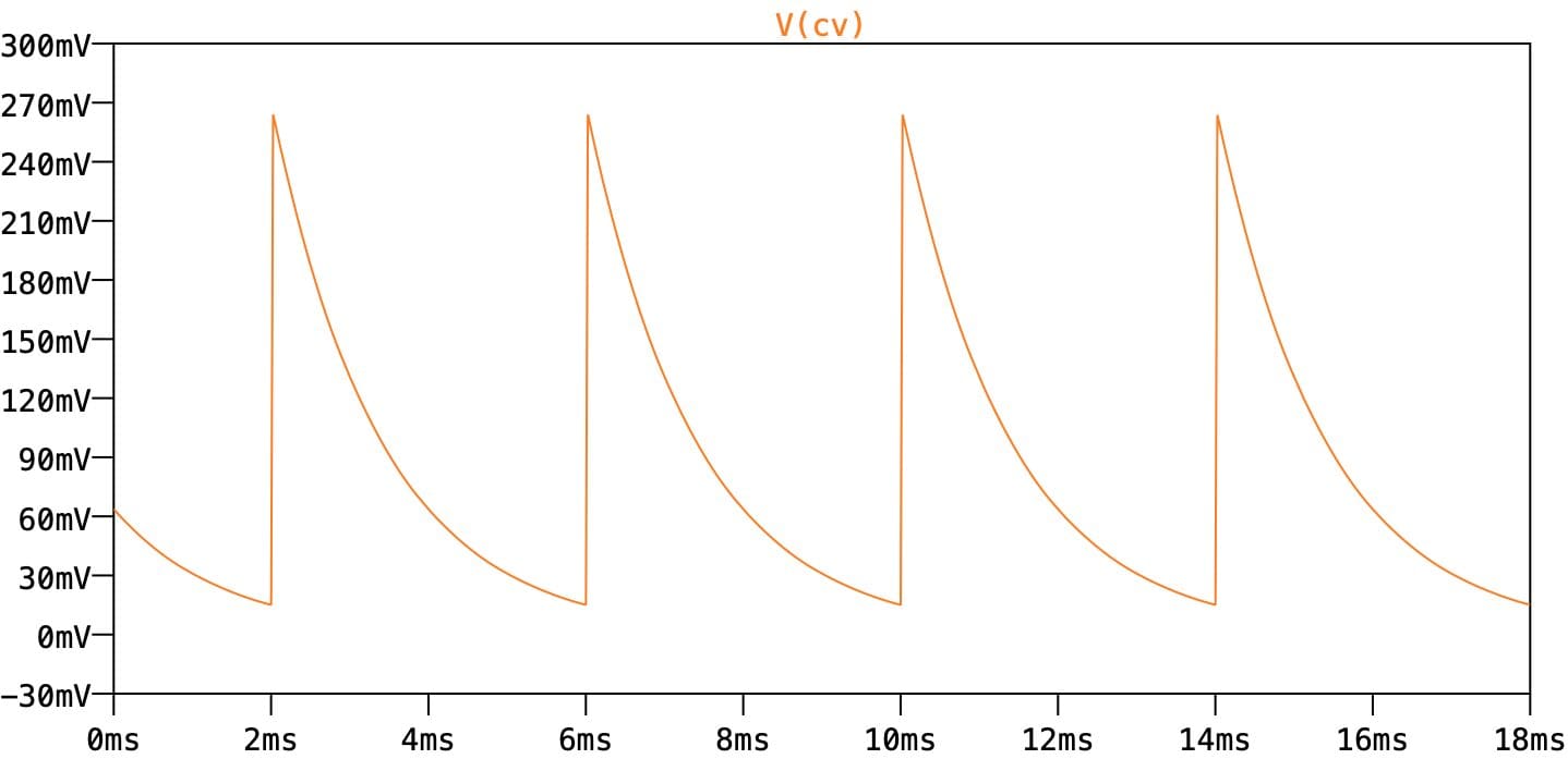
The value of C6 is a crucial choice. The 22n value Roland chose is not large enough to completely filter the pulses from the 555, so some voltage ripple remains embedded on the output voltage going out to the ramp integrator. This ripple is the ultimate source of the waveform anomalies in the Jupiter 4. So why not increase the value of C6? Boosting it to 220n is enough to completely smooth the DC output, remove the ripple, and fix the Jupiter 4’s waveforms. So why didn’t they do that? Well, because there’s a side effect. While it works perfectly well for a fixed frequency, it doesn’t work if you rapidly jump from one note to another. The smoothing is so heavy that the DC level cannot quickly jump to the new output level. Instead, it slews slowly from one to another. This is a not a portamento since it’s not a Pitch CV, but it affects the ramp waveform’s amplitude when the pitch changes. Roland avoided this problem with a compromise value which provides reasonable smoothing but also fast changes. You can’t do both.
Divider and octave selection
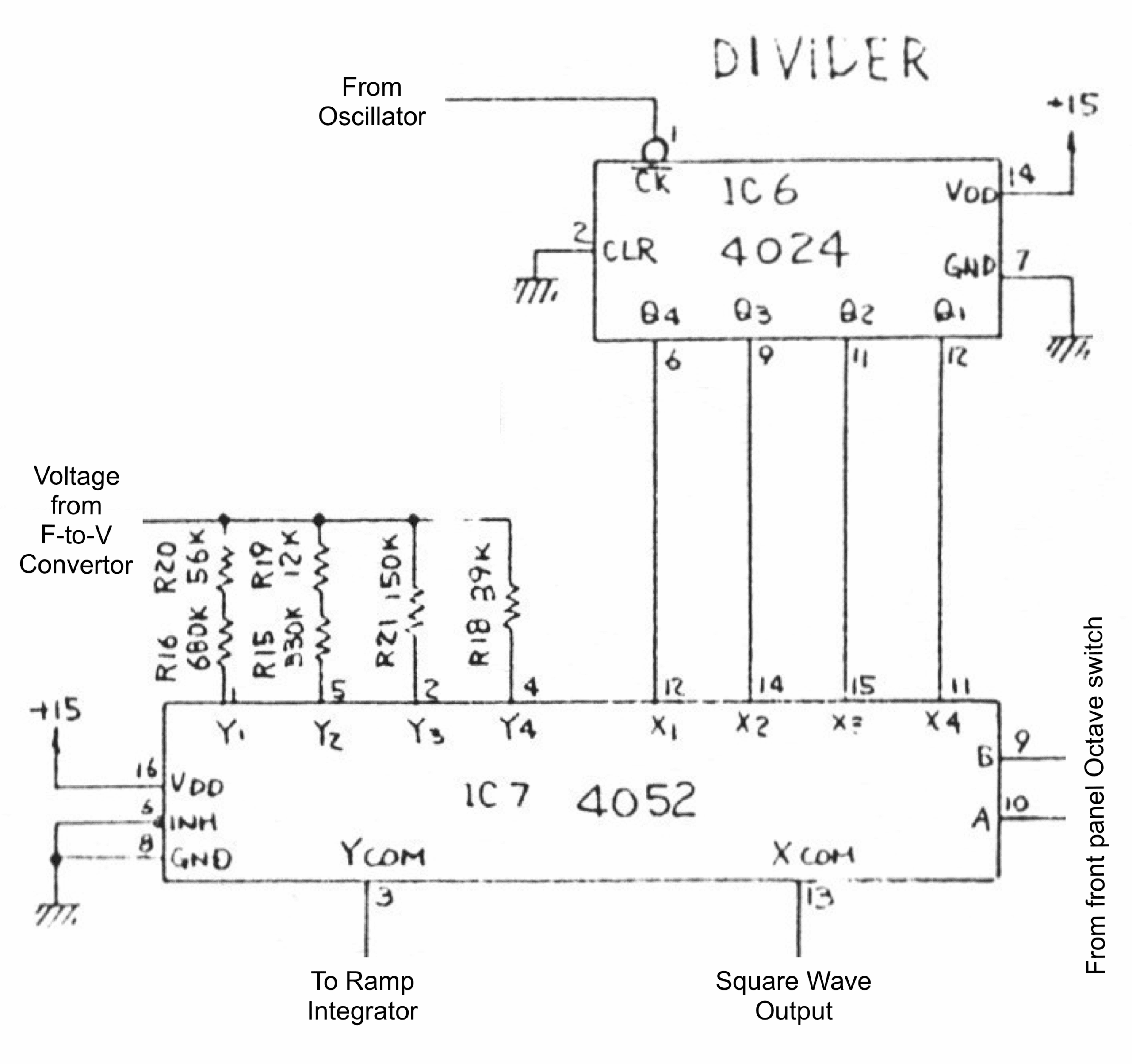 Four stages of the 4024 ripple counter are used to derive four different octaves from the input frequency. It’s a seven-stage counter chip, so this uses only a bit over half of it. These four octaves are then sent to half of a 4052 CMOS 4-to-1 demux, which is controlled from the front panel octave control.
The other half of the demux is used to select between four different resistor values. These resistors are used to alter the rate the ramp integrator charges at from the frequency-to-voltage output. This is the same amplitude compensation you see in Roland’s DCO design. If you don’t change the charging rate to match the frequency, the amplitude will halve every octave.
Notice that resistor pairs are used to get specific values, but they don’t closely follow the multiples-of-two pattern we’d expect. The values go 39K, 150K, 342K, 736K. It seems to work nonetheless.
Ramp integrator and integrator reset
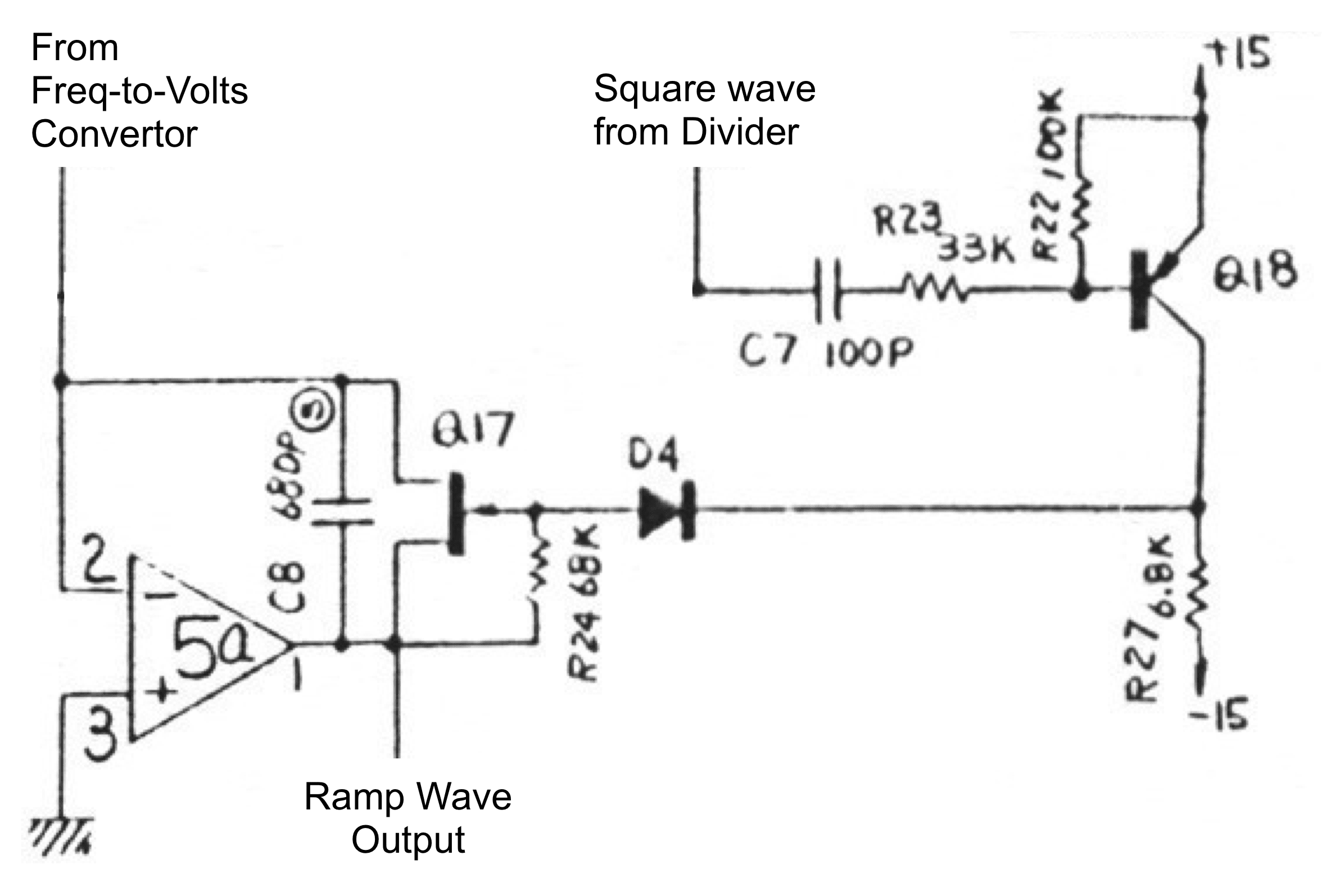
This part of the circuit is the same sort of ramp integrator that you would see in a ramp-core oscillator. However, here it is used more like in a DCO, to derive a ramp output from a squarewave signal.
The reason this is more like a DCO is because there is no comparator to generate the reset pulses, so the level of the ramp output does not affect the frequency at all. Instead, the frequency is determined elsewhere, and the ramp integrator is sync’d to that frequency by the incoming reset pulses. This is exactly the situation in a DCO – although at this point in time, DCOs didn’t exist yet.
The circuit around Q18 converts the square wave signals coming from divider into short pulses to reset the integrator, and the FET Q17 shorts out the C8/680p integration capacitor and resets the ramp wave. The charging current has to be varied to match the required frequency otherwise the ramp amplitude will vary. Now we finally see the point of the 555 pulse shaping circuit and the Frequency-to-voltage convertor. They are all parts of a complicated analogue method to control the ramp charging current.
However, this ramp charging process is not perfect. As we’ve seen, the freq-to-volt convertor output has some ripple and that feeds into the integrator. This means the ramp output is not a linear slope, but instead a series of cap charging curves stuck end to end.
The number of little curves making up our ramp waveform depends on the octaves selected. For the lowest octave, the ramp frequency is sixteen times lower than the oscillator core, so there are sixteen curves and the ramp wave is a reasonable approximation to linear. In the highest octave, there are only two curves and it’s not very linear at all.
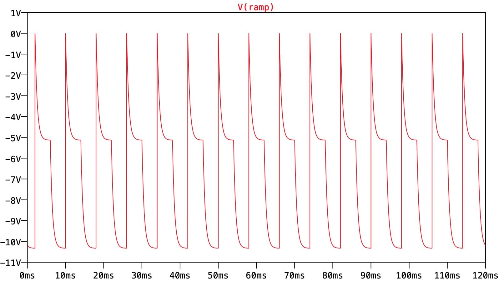
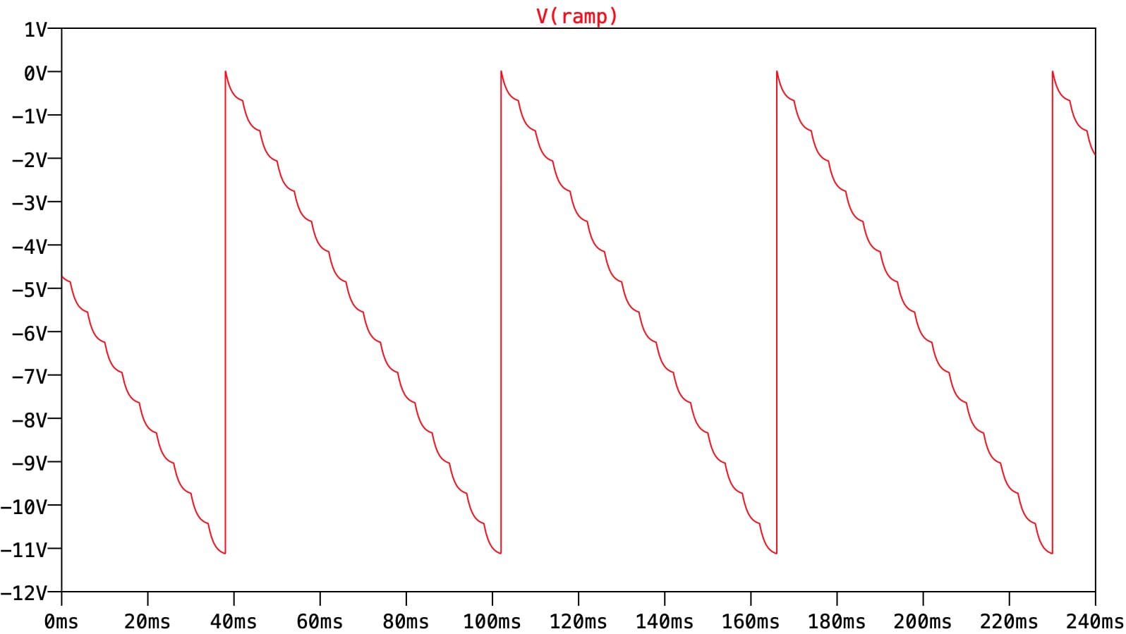
This distortion of the ramp waveform has harmonic consequences, and this gives the Jupiter 4’s oscillator some of its character.
The rest of it
PWM comparator
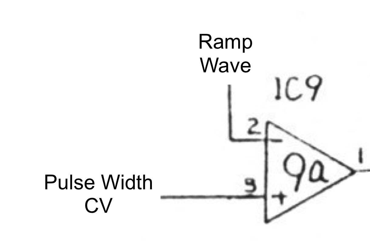 The pulse wave signal is generated in the usual way. In this case, half of a µPC4558 op-amp is used as a comparator, with the ramp wave signal into one input and the Pulse Width CV into the other. Since the Pulse Width CV is used as a threshold for the output, the useful range of the Pulse Width CV is the peak-to-peak amplitude of the ramp waveform, from 0V down to -10V.
Since the ramp wave is not smoothly linear, the relation between Pulse Width CV and pulse width is not linear either. The pulse width will increase more quickly at some points than others, giving the Jupiter 4 a particularly quirky PWM sound, especially in the highest octaves where the ramp nonlinearity is worst.
Sub-Oscillator
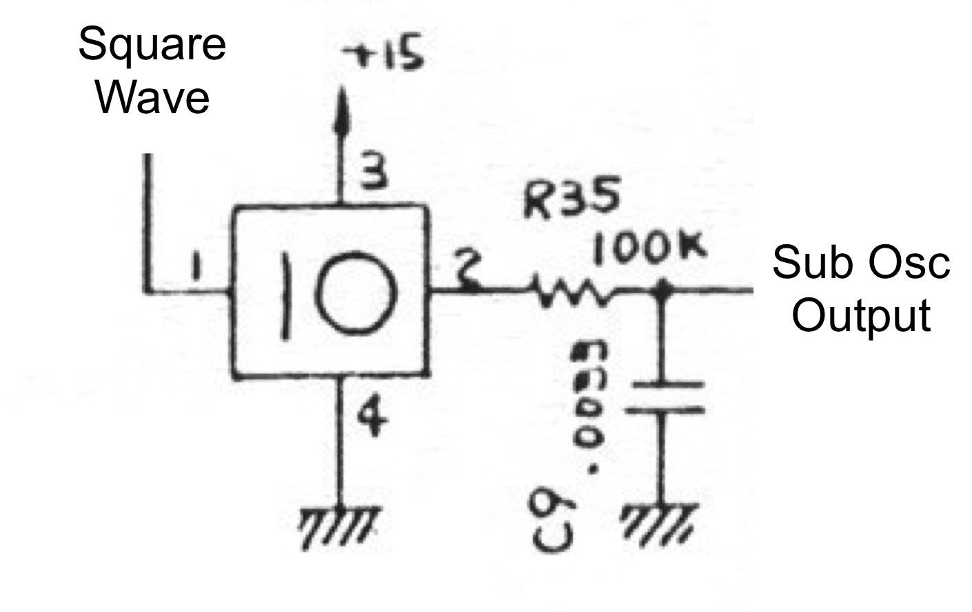 The sub-oscillator is based on a DN819 frequency divider. This is a single T-type flip-flop in a 4-pin SIL package. It takes its square wave input from the frequency divider stage. The 100K/3n3 lowpass on the output gives a cutoff of 482Hz, so the sub-oscillator is quite heavily smoothed and loses a lot of its higher harmonics. As you go up a few notes above Concert A (440Hz) you’ll get into territory where the sub-osc’s fundamental is also attenuated.
Waveform selection
 The waveform selection circuit is another part which is quite typical. It uses a 4016 quad SPST CMOS switch IC to switch waveforms on and off. Selected waveforms are mixed together by IC9b. Different input resistor values are used for each waveform to compensate for the different peak-to-peak waveform levels. The signal direct from the divider is used to provide a dedicated Square wave. Since this is from a divider, it can be guaranteed to be a strict 50/50% duty cycle square wave. You don’t have to select the Pulse wave and then try and tune it for the point where the even harmonics drop out as you do on many synths. Given the quirky pulse width control, this is probably for the best.
The Prophet 5 has a very similar looking circuit for the waveform selection, except in that case, the signals are mixed together into two separate VCAs for Osc A and Osc B.
Note that neither the Prophet 5 or the Jupiter 4 use the trick you see on later instruments of setting the Pulse Width CV to an extreme value to disable the Pulse output and thereby save a CMOS switch. There’s an explicit 4016 section for the Pulse in both cases.
Brilliant article Tom! Re IC5b.. someone on MW seems to have an explanation if you scroll down the page. I’m not sure if it answers your question or not tho?
https://www.modwiggler.com/forum/viewtopic.php?t=259604
Thanks Mark – and thanks for the ideas and the discussion too! This is what it turned into.
I suppose fundementally I don’t really get why the feedback is necessary. It’s the feedback that makes the comparator necessary. But then feedback is able to force some linearity out of something that’s probably not that linear otherwise, so that’s probably why.
It’s all rather over-complicated though. There’s current sources and critical timing caps all over the place! One thing to be said for it though is that it’s remarkably light on trimmers. That’s quite impressive.
Hi Tom. I suspect the IC5b integrator is used to linearise the pulse oscillator.
Positive current pulses from the output of the 555 monostable are summed with the negative exponential current from IC2 at IC5 pin 6. The integrator averages out the sum and adjusts the frequency of the oscillator to maintain the virtual earth at its input.
Using this feedback loop the frequency of the oscillator is directly proprtional to the exponential control current and non-linearities introduced by reset time of the oscillator, and temperature variations of C3, D2 and IC4 switching times are eliminated.
I have used this type of circuit many times for similar applications.
Thanks Paul. This type of linearizstion is what I suspected, but it’s nice to have that confirmed. You have a better grip on this stuff than I.
There’s a lot of limits on the maximum rate of frequency change in this circuit! This integrator in the oscillator control is one, and the F-to-V stage capacitor is another. Nonetheless, “Portamento that you can’t remove” is not a complaint I’ve ever seen about this synth, so Roland must have judged it pretty finely!
This type of frequency feedback loop is particularly useful with high frequency VCOs where finite ramp reset times can cause significant non-linearitities. (The Stamp Digital Delay module uses it). The down side is that the integrator limits the maximum speed of frequency change.
The time constant of the integrator has to be large enough to prevent the VCO modulating itself and small enough to not introduce a noticeable portamento effect (as you point out) or degrade LFO modulation of the VCO. However, unlike a directly controlled VCO, this arrangement makes it unsuitable for FM effects where another audio frequency signal is used as a modulating source.
Good point about audio-rate FM not being possible in such a design. That is a notable limitation. Thinking about it a bit more though, the DCO-style ramp wave would have done for any hope of FM, even if this osc core could cope with it.