
Let’s continue our deep dive into analogue drums with a look at something even earlier – the Korg KR-55. This is a preset drum machine from 1979. It uses a Read-Only Memory (ROM) to store patterns, but it has no processor, unlike the Boss Dr. Rhythm we looked at. Consequently the digital side of this machine is a complete mess of what’s known loosely as “glue logic” – individual logic chips used to stick stuff together. While there is some wild stuff in there, I’m only going to take a brief look at how they stored and retrieved programmed drum patterns in a machine with no processor. If you want to take a look, you can see the whole lot in the Korg KR-55 schematics.
Korg KR-55 Pattern Storage
The main pattern storage is a single 2048 x 8-bit ROM chip. Yes, a stunning 2K of space for patterns. To be fair to Korg, it wasn’t long later that they released the KR-55B, which doubled the ROM size to 4K. The ROM is very simple. It has 11 pins that allow you to set an address in binary (0 to 2047), three “chip select” pins, and 8 output pins that provide one byte of data. One of the clever things we’ll have a look at is how they controlled 12 sounds with only 8 outputs.
Before we start in detail, let’s have a look at how the patterns are organised. When I first looked at the front panel of this drum machine I saw 16 buttons that select rhythms and three A, B, C buttons that seemed to provide three different banks of patterns. That’s not really how Korg think about it or organise it. Instead, the 16 buttons select 16 different “rhythm groups” (Rock, Waltz, Latin, whatever) and the A, B, C buttons provide variations within that group – three loosely related patterns. It’s pretty much totally the other way around from how I interpreted it – there are 16 groups with three patterns each, not the other way around. This is important because this concept is reflected all the way down to the hardware level of the machine.
ROM Address generation

Step Counter, Bits A0 to A4
The first five bits of the ROM address generation are created by a 5-bit binary counter. These five bits count through the individual steps of the pattern. A 5-bit counter could easily be on a single chip, but this is 1979, so it’s implemented here using five individual flip-flops off three separate 4013 dual flip-flop chips (shown in blue). The use of five bits is important since it means the patterns potentially have 32 steps. The sixth flip-flop (shown in green) is used to divide the clock frequency by two before it gets to the counter and make a square wave which is then fed to one of the ROM’s ChipSelect inputs (line shown in green). The effect of this is to mask the outputs so that the trigger outputs go high for half the output period. The tempo range is from 38bpm to 380bpm which gives 200msecs to 20msec trigger pulses, but since we only really care about the leading edge, this doesn’t matter. It’s worth noting that the trigger pulses are not a fixed length though. Far from it.

Rhythm Select buttons, Bits A5 to A8
The next four bits are the “rhythm select” that you see on the front panel, the rhythm group select, lines A5 to A8. This is done using a row of sixteen buttons. Each button has listed next to it the three rhythms you can select with that button pressed down. Pressing down a button provides the relevant binary code on the four output lines. This is done using diodes. Here’s a simplified 2-bit example:

Starting with the diagram on the left, each button is connected in a chain to +5V. Each button can be provided with a pair of diodes to allow it to power up the output lines. Both output lines, Bits 0 and 1, are held low by 100K resistors by default. When a button is pressed, any connected diodes carry the +5V signal to that output line. Since we want our buttons to generate the binary series of codes 00, 01, 10, 11, the first button needs no diodes, the second button needs only one diode connected to the Bit 0 line, the third button needs only one diode connected to the Bit 1 line, and only the fourth button needs two diodes. Removing the unneeded connections shown in red gives us the actual circuit shown in the diagram on the right. The KR-55 rhythm group select buttons work in exactly this way, but extend the circuit to 4 bits (16 values from 0 to 15 in binary). This is shown below. Notice also that the chaining of the +5V supply through the buttons from highest to lowest gives higher numbered buttons priority over lower buttons. Pressing 2 overrides 1, and pressing 3 will override 2, etc.

Pattern Variation, Bits A9 and A10
The final two address bits are selected using the three coloured A, B, and C buttons. These buttons select one specific pattern within the current group. Again, diodes are used to generate the required bit values, exactly as we’ve just seen. Since there are only three buttons, only three values are available: 01, 10, and 11. The 00 value seems to be used for the Intro and Fill patterns – they’re essentially the fourth variation of the group. This is clever because for any of the other three variations, the relevant Intro pattern or Fill-in pattern can be addressed simply by pulling both of these address lines low for one bar. So you hit the “Fill” button and the machine pulls both these lines low, and no matter what pattern you have selected you instantly jump to the correct fill-in pattern for this rhythm group.
That all seems fairly straightforward, but that’s only the broad outline. There’s a lot of logic to deal with exceptions. Some of the rhythms are in 3/4 time, so they only use 12 of the 16 available steps in a bar, or 24 of the available steps in a pattern, so there’s logic to reset the flip-flops of the step counter at 24 steps for those patterns. Some rhythms are in 5/4 time, so they use 20 steps of the 32 available in a two-bar pattern, so there’s logic to reset the counter at 20 steps for those patterns. Some of the patterns are two bars long, so use the full 32 steps, whereas others are only one bar long, so only use 16 steps. I suspect this is done by simply repeating the one-bar patterns twice in the memory to avoid having even more logic to deal with that! Some of the patterns are “Swing” patterns and automatically turn on the swing feature, so there’s logic for that – although you can override it with the Swing switch on the panel by setting it to “All Rhythms”.
How do we control 12 sounds with only 8 outputs?
The KR-55 includes twelve sounds, but the ROM memory only has eight outputs, so how is this dealt with? There are two different things going on, which overlap. All in all, it’s very flexible and quite cunning. The sixteen rhythm group buttons don’t only have diodes that set up a 4-bit address. There are also two further sets of diodes that set the state of three control lines, labelled “a“, “b“, and “c” (although nothing to do with the buttons with those names). These three lines are shown below in red, green, and blue, with the two additional sets of diodes marked.

Instrument selection
We’ll start by looking at the simpler “c” control line. The Low Conga circuit uses this line to switch in different components and turn it into a Bass Tom sound. The High Conga circuit does the same thing and becomes a Tom Tom. We’ll look at that in more detail when we get to the voice circuits. This gives an either/or action on these two sounds. A rhythm group can either have Conga sounds, or Tom sounds, but not both. We can see from the diode positions in the schematic above that the c control line is high for rhythm groups 3, 4, 10, 11, and 12. That’s the 5/4 Beats, the Mambo/Rumba/Beguine group, the Swing patterns, the Bossanovas, and the Chacha/Samba/Afro group. These all use Congas. Everything else uses Toms. This is confirmed by the rhythm charts in the back of the user guide.
ROM Output Multiplexing
Even using this either/or switching, we still have ten separate instruments to control with only eight lines. This is where the multiplexer comes in. Six of the sounds have dedicated outputs (Bass, Snare, Cymbal, Open Hat, Closed Hat, and Low Conga/Tom). The remaining two outputs can be routed to the remaining four instruments (High Conga/Tom, Rimshot, Cowbell, and Claves) using a CMOS 4052 dual 1-to-4 switch attached to the outputs of the ROM. There are 12 potential routings, but only six distinct combinations (Rimshot+Cowbell is the same as Cowbell+Rimshot, for example). We are offered these four options from the six:
| b | a | Output 7 | Output 8 |
| 0 | 0 | High Conga/Tom | Rimshot |
| 0 | 1 | High Conga/Tom | Cowbell |
| 1 | 0 | High Conga/Tom | Claves |
| 1 | 1 | Rimshot | Cowbell |
They left out Rimshot+Claves, and Cowbell+Claves. This choice was presumably made because these four options covered the requirements of the patterns they had designed. The clever bit is that depending on the setting of line c, those Conga+Rimshot, Conga+Cowbell, and Conga+Claves combinations could actually be Tomtom+Rimshot, Tomtom+Cowbell, and Tomtom+Claves. So it is pretty versatile.
We can work out from the diode positions which rhythm groups use which multiplexer settings, like we did for the instrument selection. Button 4(Mambo/Rumba/beguine) has a diode to line b, so takes that line high. That gives the High Conga+Claves combination. Buttons 6(Rock), 8(Disco), and 15(Rock) have a diode to line a, so use the High Conga+Cowbell combination. Buttons 11(Bossanova) and 12(Chacha/Samba/Afro) have two diodes and take both lines high, giving the Rimshot+Claves combination. Everything else is set for High Conga+Rimshot, if the pattern actually uses those sounds at all.
How many patterns are there in the KR-55?
Several sources on the internet claim there are “up to” 96 patterns. That’s true for the KR-55B, but not for the KR-55. This is calculated by taking the 16 rhythm group buttons on the front panel and multiplying by 3 variations (A, B, C) to give 48 patterns. This is then doubled, since each pattern has a fill or intro pattern too. However, this isn’t quite right.
Firstly, we know this isn’t quite right because there isn’t enough memory. 96 x 32 steps for each pattern is 3072 bytes, which is 50% more than we have available. While it’s possible that Korg did something clever and combined two one-bar patterns into one address space, it’s not likely. Secondly, we know this isn’t quite right because the manual tells us so! It says:
There are fill-in patterns for each rhythm group (Like ROCK 1,2,3 or Waltz 1,2,3).
Korg KR-55 User Manual, page 7
That implies there is a different Intro and Fill-In pattern for each group of rhythms, not each rhythm.
The manual also says:
Intro and Fill-In patterns are one measure long for all patterns, except Ballad.
Korg KR-55 User Manual, page 7
The Ballad exception isn’t really an exception. In reality, the Ballad Intro and Fill-Ins are one measure long too, except that the Ballad rhythms use a halved tempo, so they seem to take twice as long. They don’t, however, use any extra memory.
So what have we got? The final tally is 16 x 3 basic patterns of up to 32 steps, plus 16 Intro patterns and 16 Fill-In patterns of 16 steps each. The total number of bytes required for this is:
(16 x 3 x 32) + (16 x 16) + (16 x 16) = 2048Well, would you believe it?!? That’s exactly how many bytes we have in our ROM! So the truth is that there are 48 basic patterns, plus 16 intro patterns and 16 fill-in patterns, which is only 80 patterns, not 96. Each rhythm group has both an intro pattern and a fill-in pattern.
Elements of the Drum Voice Circuits
Like I did last time, I’m going to start with a look at some of the elements that feature in the drum circuits we’ll look at in a minute, and some of the circuits that generate the “raw material” in audio terms that they’ll work with.
White Noise Generator
One difference between the DR-110 and the KR-55 is how they make white noise. The DR-110 uses a digital-shift-register-based LFSR noise generator, whereas the earlier KR-55 uses a classic analogue transistor-based noise source. The trouble with transistor noise sources is that they’re not very reliable. The original Korg schematics mention that the noise transistor has been selected – e.g. someone had to test several to find one that generated a good level of noise. Even “noisy” transistors only generate a very low level noise signal, and this leads to the second problem with transistor noise sources – they need a lot of gain. Now, clearly, we don’t mind if the amplifier is a bit noisy, since we’re *trying* to make noise, but what about if it picks up even a little bit of mains hum? The last thing we want in our supposedly “white” noise is a lot of 50/60Hz hum, and the gain makes them pretty sensitive. It’s no wonder that later instruments started moving away from analogue noise sources. The digital sources provide a more reliable sound with no time-consuming selection process required and a cleaner noise signal (if that makes sense!).
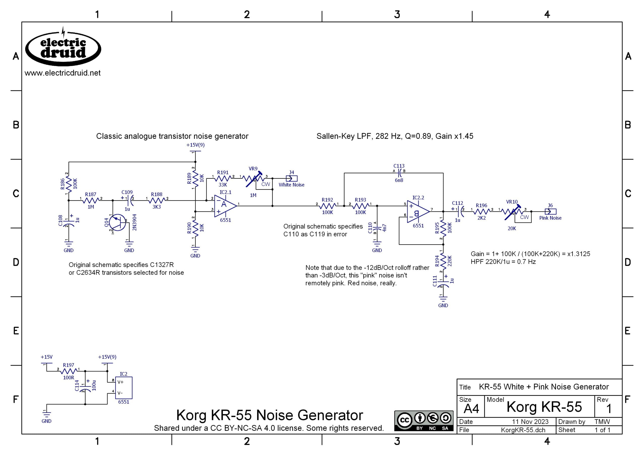
The noise is created by Q14, and yes, it’s supposed to have one leg floating about unconnected like that! It’s that reverse-biased Emitter-Base junction that creates the noise. It’s transistor abuse is what it is. The noise is coupled through C109/1µF to the inverting amplifier based around IC2.1. This has a basic gain of 33K/3K3 = x 10 or +20dB, but the 1M trimmer allows this to be massively boosted to +50dB. The white noise source is followed by a straightforward Sallen-Key filter to remove some of the high frequency content of the noise. The filter has a bit of gain, since the filtering process will reduce the overall level. Korg call this a “pink noise” signal, but this is definitely playing fast and loose with the terminology, since pink noise is defined as having a slope of -3dB/octave, and their filter will give a slope of -12dB/oct, so the resulting noise has much more bass and much less treble than genuine pink noise. It’s more “red noise”.
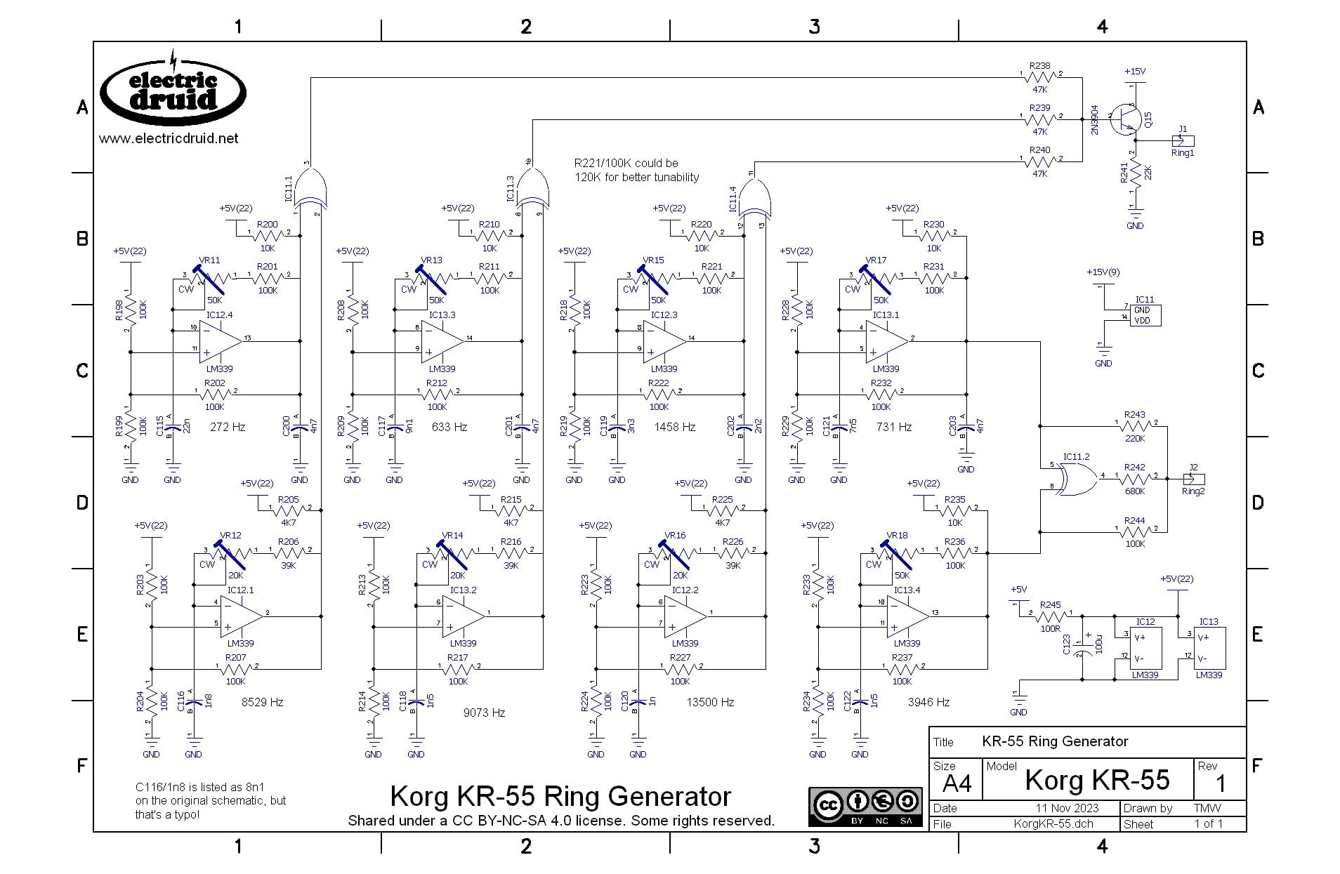
Ring generator
Besides the white and pink noise signals, there are two signals inside the KR-55 called “Ring1” and “Ring2”. These are the equivalents of the DR-110’s “Low Metal” and “High Metal” signals, and are used for the same purpose – synthesis of clangorous, metallic sounds like cymbals and bells. However, here they are created in quite a different manner and treated somewhat differently. It starts the same way, with some basic “square wave” oscillators. The DR-110 used oscillators based on a pair of schmitt trigger inverter gates. The KR-55 uses oscillators based around LM339 comparators.
Comparing the DR-110 and KR-55 cymbal generators

The DR-110 ony uses four different frequencies, and then mixes those with white noise and then filters the result.

The KR-55 goes a different way, and uses six oscillators, which it then mixes together in pairs using CMOS 4070 XOR gates. XOR is an interesting function because for square wave signals like these, XOR’ing them together is equivalent to ring modulation, and what you get out of the other end is sum and difference frequencies. So if you put in Frequency X and Frequency Y, you get X+Y and X-Y. But we’re not putting in only one frequency. These aren’t pure sine waves but rich square or pulse waves with lots of harmonics at multiples of the fundamental frequency. So we get X+Y, but we also get 3X+Y, and 5X+Y, and 3X+3Y, and 3X+5Y, etc etc. And then there’s all the difference tones too: 3X-Y, 5X-Y, 5X-3Y, etc etc. It gets very complicated very fast!!
That would be bad enough, but we do that three times, with three different pairs of unrelated frequencies at IC1.1, IC1.3 and IC1.4, and then we mix the result together so we have a very rich, not-quite-noise signal for making cymbals with.
The Ring2 signal is not as complicated. It uses one pair of oscilators and one XOR to generate the output. Unlike the Ring1 signal, it uses R245 and R246 to mix some of the oscillator signal into the output as well, so we have the original X and Y frequencies as well as all their sums and differences. This fills in the sound a bit more, but also gives it more of a sense of specific pitch. This Ring2 signal is used for the cowbell sound, so it is almost a pitched sound.
Also notice that the KR-55 doesn’t filter this sound, it just uses it as-is, at least at this point. The DR-110 uses bandpass filters to create the Low Metal and High Metal signals, so the noise might be metallic, but is fairly “focussed” on a certain range of the frequency spectrum. The KR-55’s Ring1 and Ring2 signals are much more “broadband” signals that cover the whole spectrum.
Envelope Generator and dual PNP VCA
The Cowbell, Cymbal, and both Hi-Hats use a simple pair of PNP transistors as a VCA. This is Korg’s version of the Roland “Swing type” VCA we looked at in the Boss DR-110 article. The specific examples vary a bit, so we’ll look at those individually, but they all share the same overall plan. It looks like this:
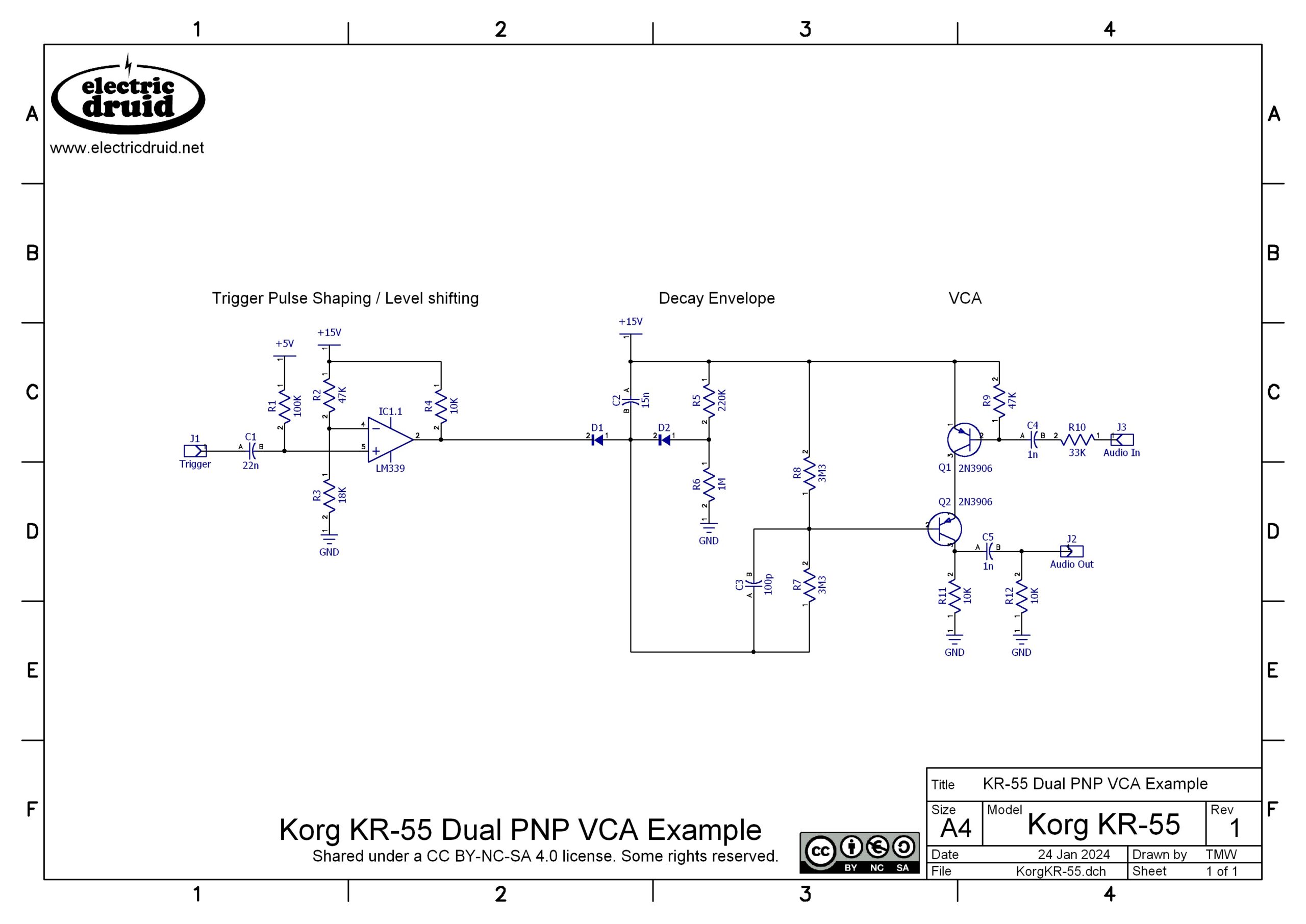
Firstly, this VCA uses 15V, and it needs a 15V envelope signal to drive it. Our 5V trigger pulses aren’t enough. The circuits all use a comparator from a LM339 quad comparator chip to boost the trigger pulse level to 15V. C1/R1 form a highpass filter that turns the edges of the trigger pulse into spikes. The comparator then turns these spikes into a solid trigger pulse. With the 22n/100K values and the threshold set by R2/R3, the pulse is about 2msecs, but this can be tuned by changing either the filter or the threshold or both.
The LM339 has “open collector” outputs. This means the output is basically just a NPN transistor with the emitter tied to Ground and the collector provided as the output. This is convenient for level-shifting like this because we can add a pull-up resistor to whatever voltage we need, in this case R4/10K to 15V. Since the transistor can pull the voltage down quicker than our 10K resistor can pull it back up, the comparator maintains the negative-going trigger pulse convention in the rest of the circuits.
Secondly, we turn that trigger pulse into a decay envelope. Since our trigger pulse is negative-going, our decay envelope is inverted. However, it’s much easier to see what’s going on if it’s not all upside-down, so here’s what the envelope circuit and VCA looks like the right way up!
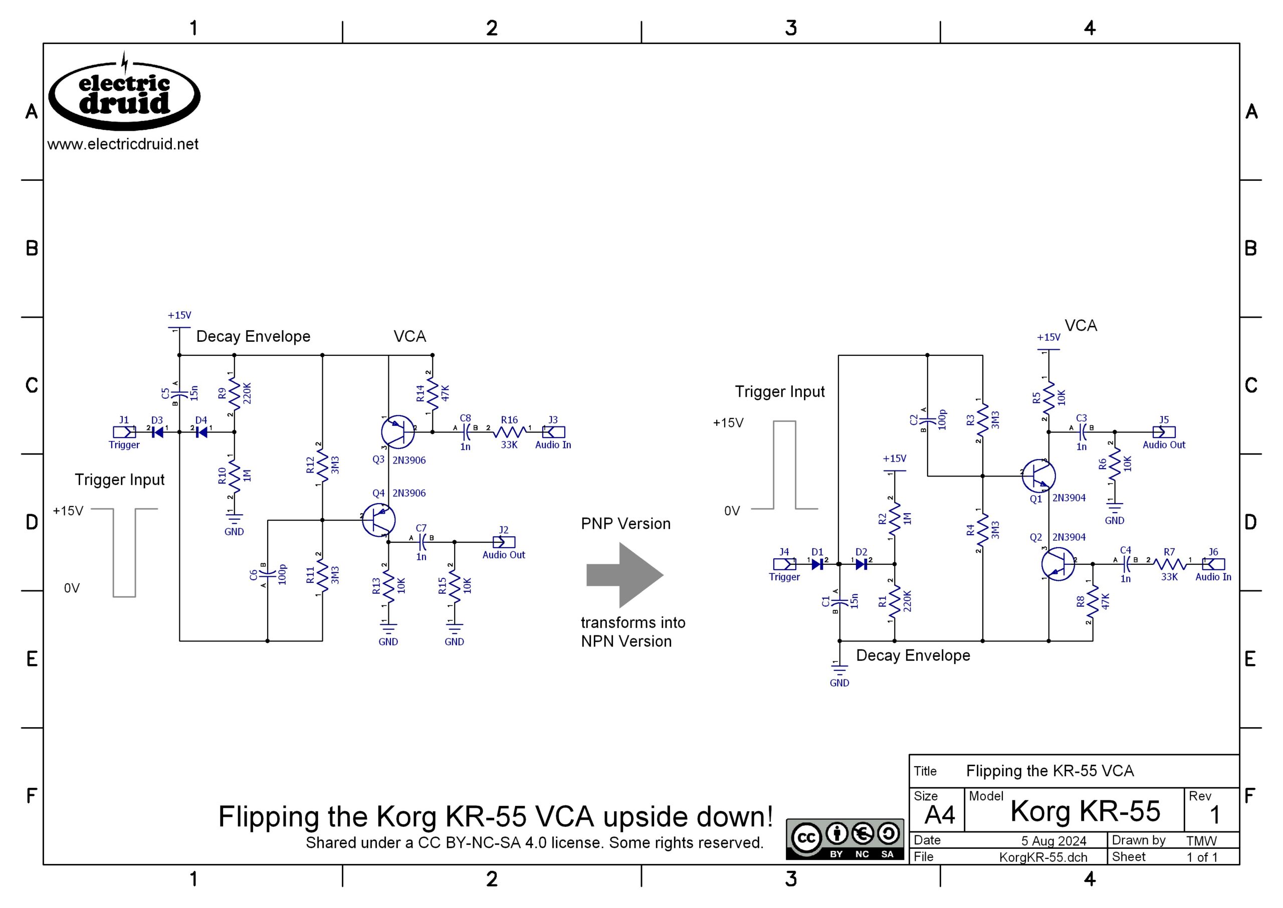
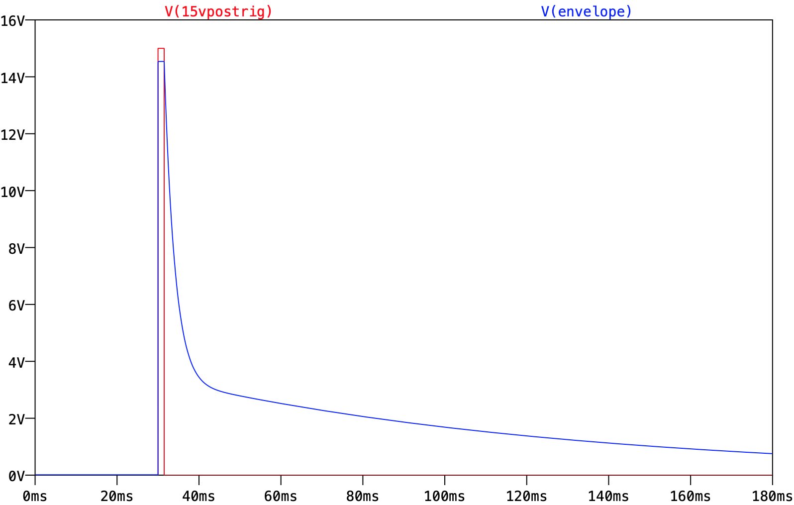
There’s a couple of details we haven’t mentioned. Notice the way that the signal for the transistor base is taken from between the two resistors? That’s done to prevent the transistor from messing things up. If the signal for the base came from directly across C1 at the top of R4, the capacitor would have a third path to discharge, through the transistor and to ground. Taking the signal from the middle point means that capacitor can’t discharge that way without going through a 3M3 resistor, which is large enough to not affect the 220K much. The other detail is that weird little cap C2 floating about there. What’s that for? Well, I think it’s a “speed up” cap. When the envelope goes high, we want Q1 to switch on rapidly. Because the base is fed by 3M3, even a small amount of parasitic capacitance in the transistor will create a significant time RC constant. The cap C2 allows the sharp edge of the attack to bypass R4 and thereby switches Q1 on much quicker than it would have done otherwise.
Finally, we come to the VCA part. A way to look at this to understand how it works is to consider it like a potential divider. Q1 and Q2 act as variable resistances at the bottom of the divider, and R5/10K provides a fixed resistor at the top. The incoming audio will turn Q2 on and off, and the envelope will turn Q1 on and off, but the final equivalent resistance depends on the current flowing through both of them. In that way, we have a multiplication action – it’s a VCA. Note that it’s not at all linear. The lower transistor Q2 has it’s base tied to +Ground, so it is tied hard off, and the incoming signal must reach a certain level before it switches on. For square wave signals like Ring1 and Ring2, this isn’t hugely important.
As the current through Q1 and Q2 alters, the voltage at the collector of Q1 goes up and down. This signal is our output. Since there is a lot of DC feedthrough from the envelope on this signal, it is highpassed by C3/R6 to remove unwanted low frequency thumps. In many of the circuits that we’ll look at, this highpass is set to remove plenty of bass or even mids and shape the tone of the result, not just to remove DC.
Korg KR-55 Drum Voice Circuits
Bass Drum
Like the Boss DR-110, the Bass drum is one of the simplest circuits in the instrument. In fact, the output of the two circuits is very similar, even down to the waveform level. The big difference is that this one uses a Bridged-T filter based around an op-amp for its resonant circuit, instead of the transistor-based phase-shift-oscillator-style that we saw in the DR-110. The KR-55 runs on a 15V single supply, so it has more headroom and op-amps are much more viable at such a voltage. Nowadays there are loads of low voltage op-amps that run at 5V, 3.3V, and even less, but that certainly wasn’t the case in 1979.
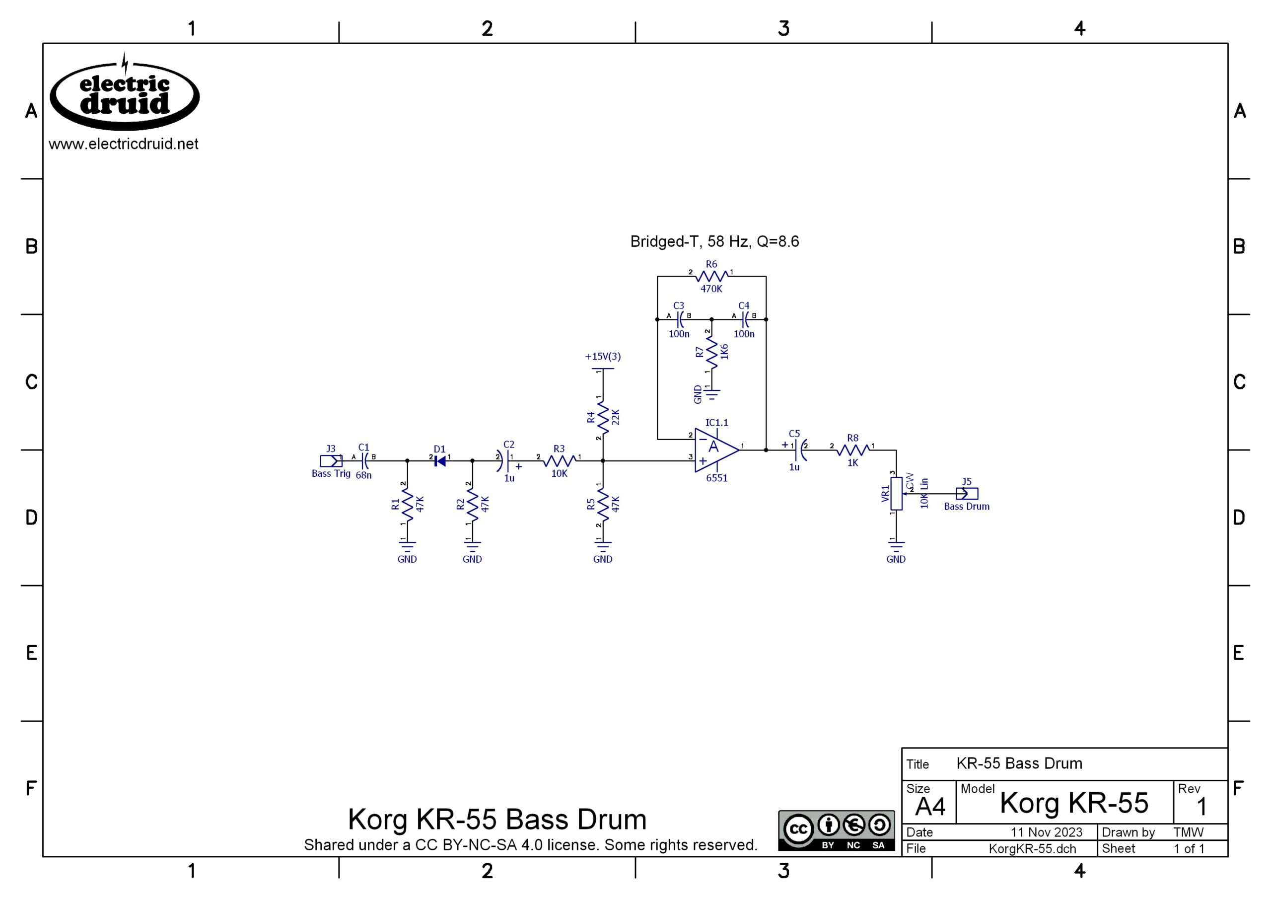
Despite the different design of damped oscillator, the idea is exactly the same: the trigger pulse is used to give the oscillator a kick, and then it “rings” for a while until the energy from the trigger pulse dies away. One other difference from the DR-110 is that the trigger pulse isn’t explicitly fed to the output, although some passes through the op-amp because of the non-inverting configuration.
One interesting thing they have done instead is to bias the op-amp deliberately off-centre. The R4/R5 voltage divider gives a bias of roughly 10V on a 15V supply. This means the signal has a lot more headroom in one direction than the other, and this makes assymetric clipping on the attck of the drum a distinct possibility. I think this is another approach to getting a bit more bite into the attack, giving more “whack” to the start of the sound.
Snare Drum
The Snare includes a few different elements, and mixes them together in different ways. The trigger comes in at the bottom-left, and C8/R12/D3/R1 turn a simple negative-going pulse into a negative-going decay envelope. Note that all these envelopes are inverted – they start high and drop low, rather than the reverse. It makes no odds to the sound. This envelope spike is used to trigger the Bridged-T filter and make the body of the snare sound.
In parallel with this, C6/R9/D2/R10/C7 make another longer envelope. Whereas the first one decays in around 5msecs, this lasts more like 50 or 60msecs. This longer envelope is mixed with the resonant output from the Bridged-T (using R11 and R22) to create a complex control signal for Q1. This gates the white noise signal into short bursts at the Bridged-T frequency. This creates the “snap” of the snare wires.
I’ve worked out the basic frequency of the Bridged-T on the schematic, but this will be modified somewhat by the diode clipping network – that will tend to raise the frequency a bit. As the signal decays and goes below the diode threshold, the effect of this will diminish, so this network has two effects. It causes the pitch to be slightly sharp initially and then fall (like a real drum), and it causes the start of the sound to be less sinusoidal than later on, adding more harmonics to the attack.
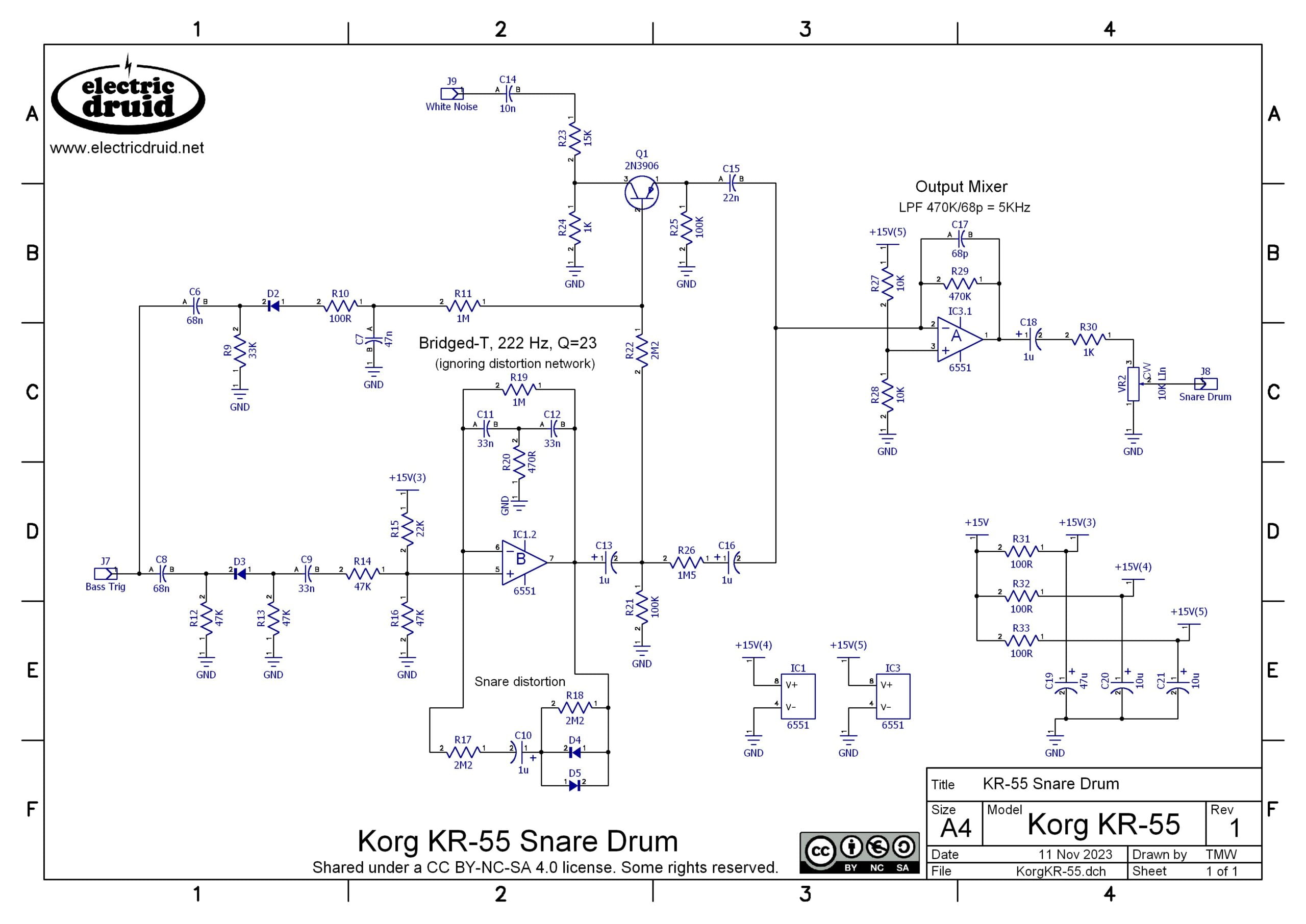
The “snare wires” signal and the “snare body” signal coming directly from the Briged-T via R26 are mixed into the output mixer IC3.1. Q1 acts as if it were a variable resistor in this situation, either passing current (like a low value resistor) or not passing current (like a really high value resistor!). The output mixer also includes a filter cap, C17/68p which is set large enough to roll off some of the high frequency edges of the sound and keep things a bit more in the midrange.
Cymbal
The cymbal sound is basically two elements, passively mixed together by R47 and R59 at the output. Both are driven by the same trigger pulse, which is 5V to 0V at the input, but is converted to 15V to 0V by IC10.3, the LM339 comparator.
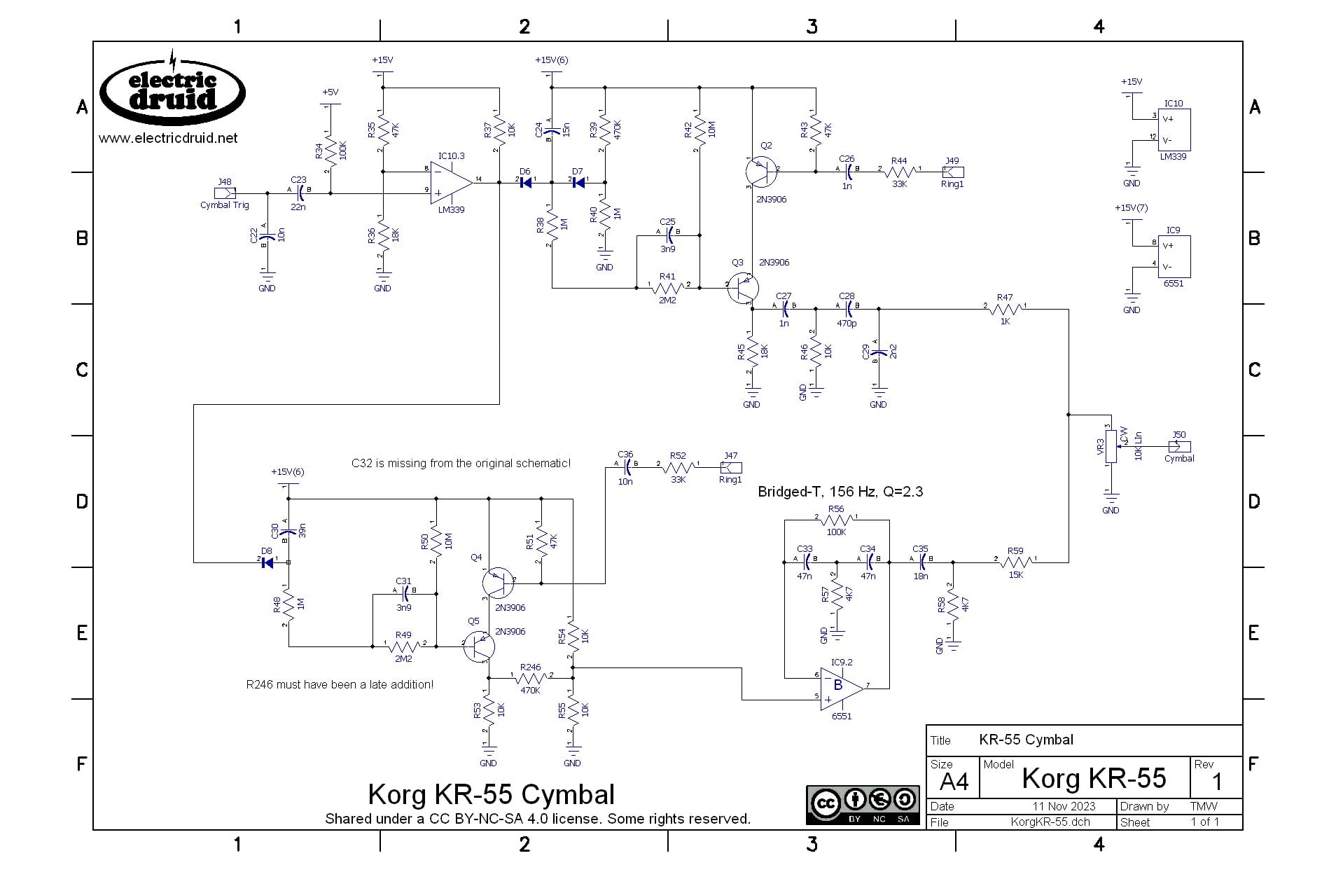
Both parts of the sound then use a simple decay envelope (C24/R38 and C10/R48) to then control one of Korg’s dual-PNP VCAs which we took a look at earlier. Both VCAs use the Ring1 metallic noise signal, but the lower channel then feeds it to a Bridged-T filter to give it a different tonality. The shorter envelope (C24/R38) produces a brief “Ting!” while the longer C10/R48 envelope gives us the more-tuned (because of the filtering) metallic body of the sound.
Hi-Hats
The hihat sound is a single element, just a enveloped burst of the Ring1 signal fed through a transistor bridged-T filter. Any complexities in this circuit come from the separate triggers for open and closed hihats and the way they interact.
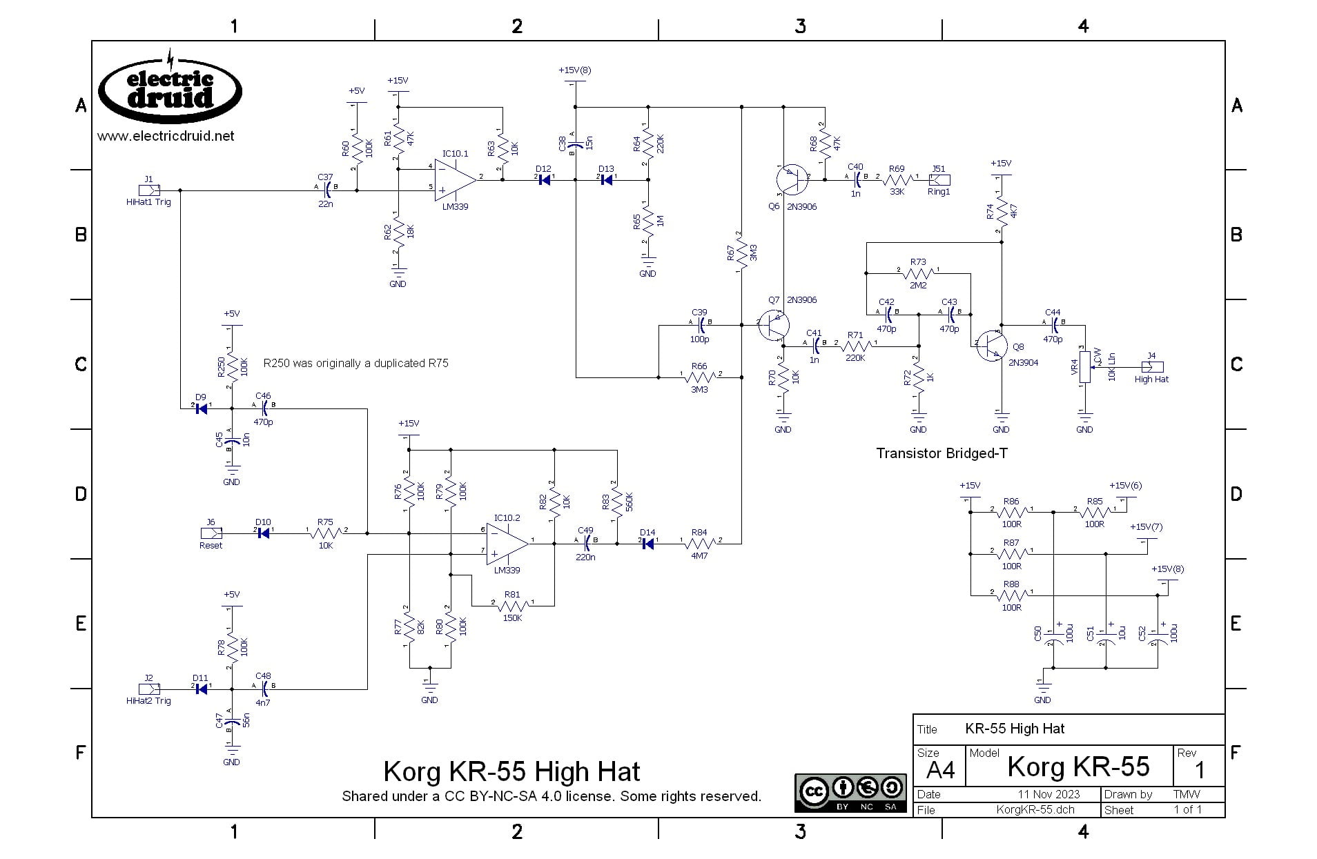
The upper part of the schematic, from HiHat1 Trig rightwards, is the closed hihat. As you can see, this uses the two-speed envelope we looked at when we talked about the VCA. This gives the sound an initial “Ting” and then a softer body. In the case of the hihat, the whole thing is over within 130msecs, so only about 1/8th of a second.
The lower part is the open hihat. This is very different. It doesn’t control the envelope, but instead plugs directly into the VCA. The behaviour of the comparator in this section is odd too. It seems to reflect whether the hihat is open or closed. When a closed hihat trigger comes along it goes high, and remains high until a Open hihat trigger resets it low. So it acts more like a flip-flop than a comparator. However, that action of the lower comparator output going low drags the base of Q7 down and holds the VCA open, so you get a long, sustained sound rather than a short brief one.
Low Conga / Bass Tom
There are both High and Low Conga / Tom Tom circuits in the KR-55, and they include a couple of switches and optional bits of circuitry to make the two different sounds. They’re both based on the same Bridged-T circuit we’ve already seen, but then they do different things to it to tweak the sound. What’s impressive is how different the two sounds become.
While R101 is the main resistor forming the “bridge” in the “Bridged-T”, the upper path above the op-amp IC4.1 is in parallel with this resistor and acts in concert with it. For large signal amplitudes, the diode pair D16/17 will conduct, putting this path into action and reducing the effective value of R101. This raises the pitch of the drum. As the amplitude falls, the diodes gradually stop conducting and the parallel path is removed and the pitch returns to normal. This gives the drum a slight pitch envelope, sharper on the attack.
For the Tom sounds, the “Not C” signal is high (I guess it means “not congas”). This switches IC5.4 on for the Bass Tom (IC5.2 in the Tom Tom), reducing the resistance in the diode-clipping path from 3M2 (2M2+1M) to 2M2. This is still a large value, but apparently makes an audible difference.
Both the Toms and the Congas use a feed from the trigger pulse to the output. We saw this in some of the DR-110 sounds, but this is the first appearance of this trick in the KR-55. The Congas use a additional “Attack” sound, but we’ll come to that in a second.
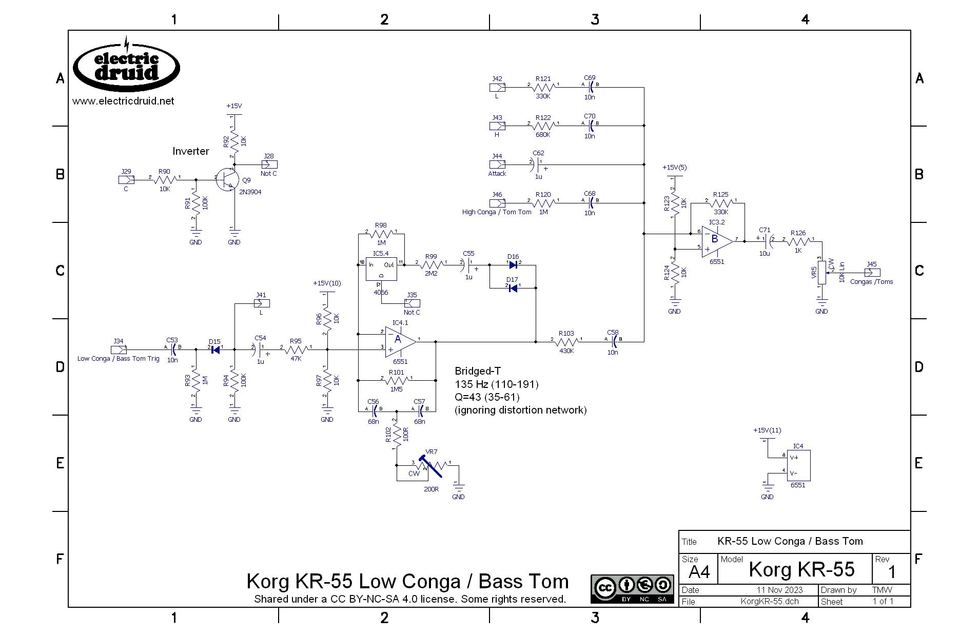
Another thing that distinguishes the Conga/Tom circuits from some of the others in this machine is that they have a trimmer for tuning. Although this trimmer is only 200Ω, it makes a significant difference, giving about 9.5 semitones of tuning range. In this circuit, you can’t alter one parameter without altering another, so the Q factor also changes, from 35 to 61. In some ways this is much less important since (a) both of these are very much “high Q” and (b) the increasing Q helps compensate for what would otherwise have been a shorter sound.
High Conga / Tom Tom
The high conga circuit is very similar to the low conga, only tuned diffently, as you’d expect. All the Bridged-T components are identical, except for the capacitors which have been reduced from 68n to 56n. That pushes the resonant frequency up a couple of semitones or so.
While it’s true that the Bridged-T components are identical to the Low Conga / Bass Tom, the clipping network is not. In this example, the 1M and 2M2 resistors swap places, with the larger 2M2 now being the one that can be shorted out by the switch. There’s also another 2M2 in parallel with the diodes, so the maximum resistance of this branch of the circuit is 5.4MΩ, which is a pretty hefty value. Since the whole lot is in parallel with the 1M5 of the Bridged-T, that much lower value will dominate, so the big changes in value aren’t as siginificant as they initially appear. The effective parallel value will change much less.
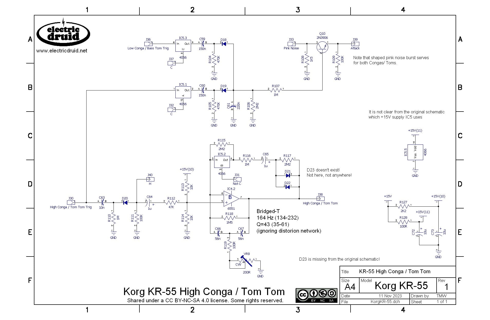
The top half of this sheet shows the two switches IC5.3 and IC5.1 which turn on a burst of pink noise for the conga sounds (controlled by the “C” logic signal). This sub-circuit is shared by the two congas. The incoming trigger pulses are turned into a brief envelope which is then used to switch on Q10 and allow a shaped burst of pink noise through to the output mixer on the Low Conga sheet.
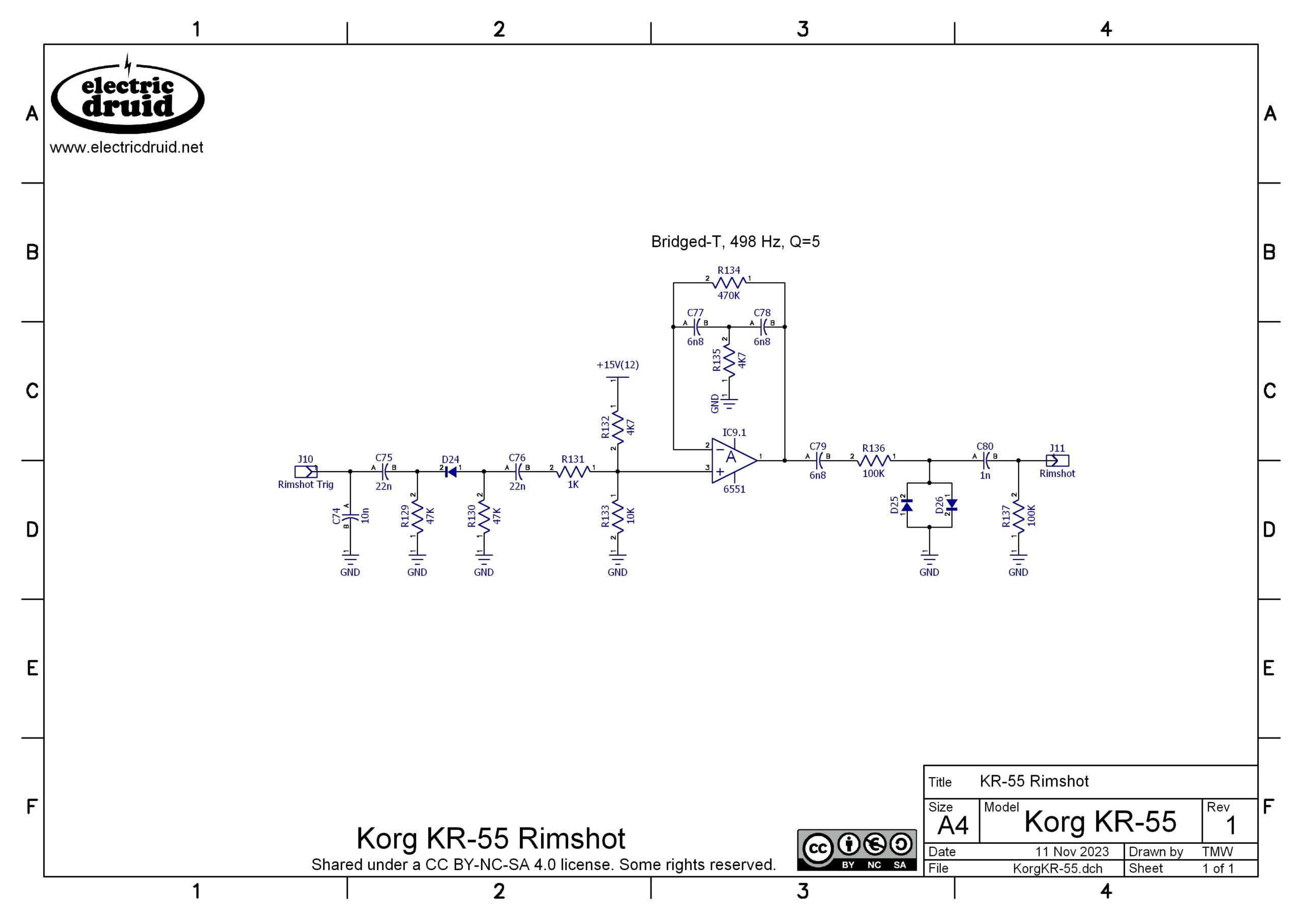
Rimshot
The rimshot is another simple Bridged-T tuned drum sound, this time with the addition of clipping diodes on the output to give it more bite. I think it’s a very effective sound for very little circuitry.
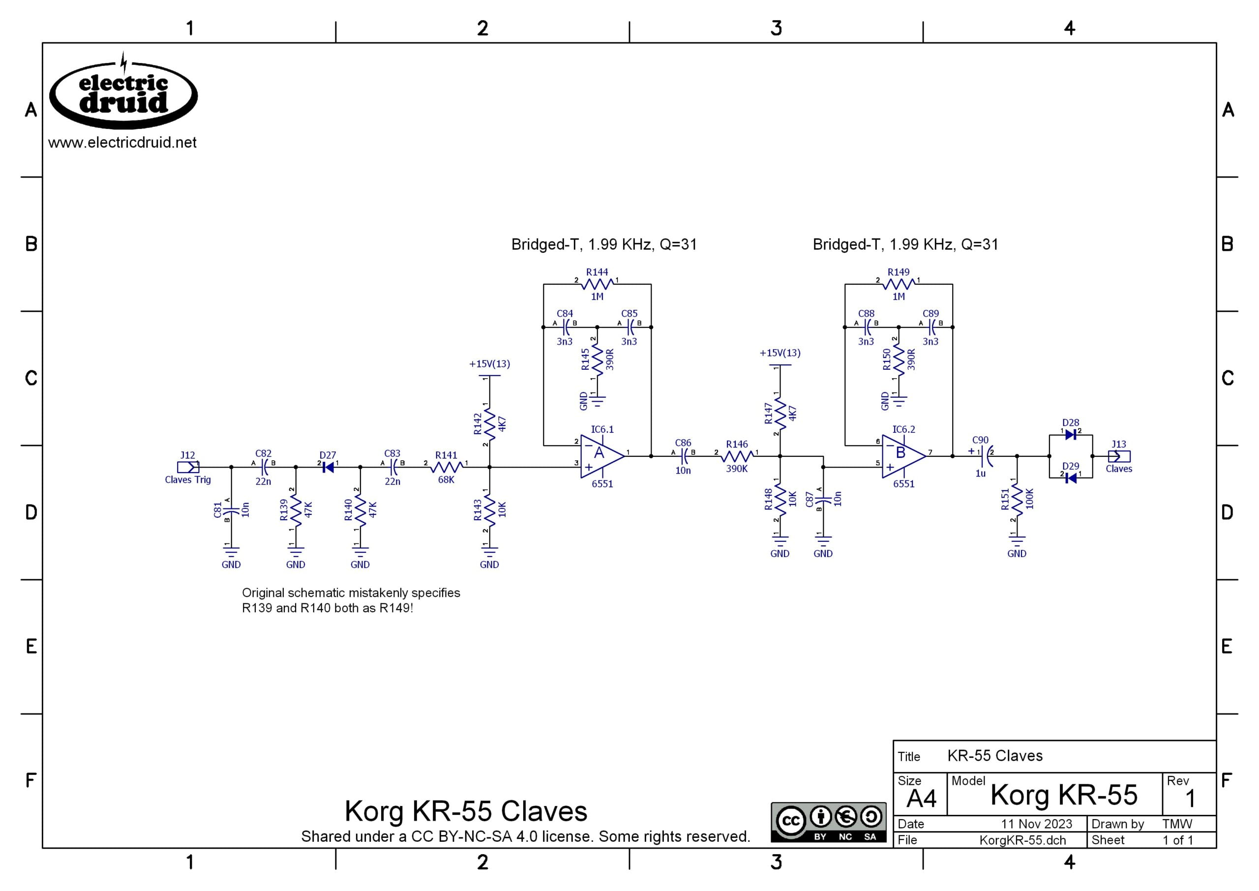
Claves
The claves sound is an interesting and unusual case. It uses two identical Bridged-T circuits, and uses the first one to trigger the second one. The output is pretty loud! The first Bridged-T is hit with a sharp spike derived from the leading edge of the trigger pulse. Again, the op-amp is biased off-centre, like we saw for the bass drum. IC6.1 produces a ringing burst of sound at its output. This sound is then passed to the next Bridged-T stage, where it is used as a trigger. Instead of being triggered by only a single hit, this second stage is triggered by a repeating series of waves. Since both T’s use the same component values, the effect is to boost the resonance way past what is possible with a single stage. This is necessary because the frequency is so high that otherwise the sound would die away extremely quickly. As it is, it is still only 25msecs long. The very high resonance makes the circuit sensitive to noise, so the two diodes D28/29 act as a simple noise gate, cutting the signal off when it drops below the diode’s forward voltage. You sometimes see this diode arrangement called a “noise corer” since it cuts out the “core” of the signal. It’s fairly common in high-gain metal distortion pedals and similar circuits.
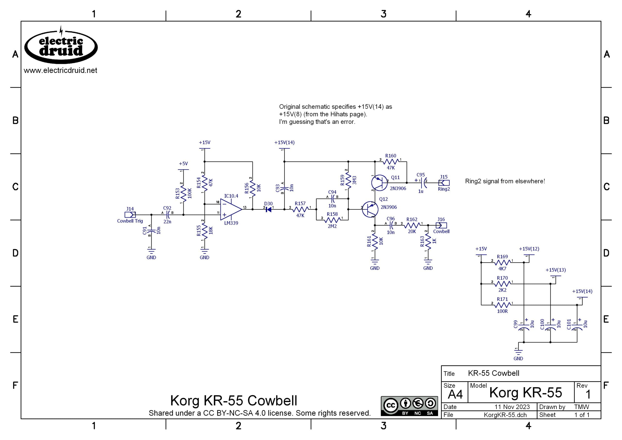
Cowbell
Now, this cowbell sound is one of my favourites, and I never thought that I’d say that after the 808 cowbell scarred me for life! But this one is actually pretty good, and while it doesn’t sound exactly like a Swiss cow wandering down the Matterhorn, we’re not paying Swiss prices. The actual sample above is slightly longer than the sound from my simulation of the circuit, and I like the sim version better. Short and snappy is good.
A lot of the work for this sound is already done for us by this point with the Ring2 signal. As we noted above, this consists of two squarewave oscillators and their XOR produt all mixed together. The addition of the XOR is really important here, since it is the major distinction between this and the TR-808 cowbell. While that sound might have become iconic (I might say “infamous”) few people would claim it was a high point of analogue drum synthesis. It is simply two pulse waves mixed together. The addition of the XOR gives the sound a more metallic edge and much more “clang”.
Audio Mixers
The various instrument signals are mixed together using a simple inverting op-amp mixer stage. However, to save having quite so many controls on the front panel, some instruments are grouped and can only have their levels controlled together. The first example is the Conga / Toms sounds, which are treated as a unit. The second example is the Rimshot / Claves / Cowbell which are treated as a group. If you have rimshot and cowbell in one pattern and you want more of one but less of the other, you can’t, sorry. I don’t know whether that situation arises much in practice. Korg could have orgainsed their patterns so that not many had these kind of combinations, so the control basically always only did one thing.
The mixer circuits themselves are pretty standard stuff. Note the range of different input resistor values (from 2K2 to 56K) to help match volume levels between different instruments.
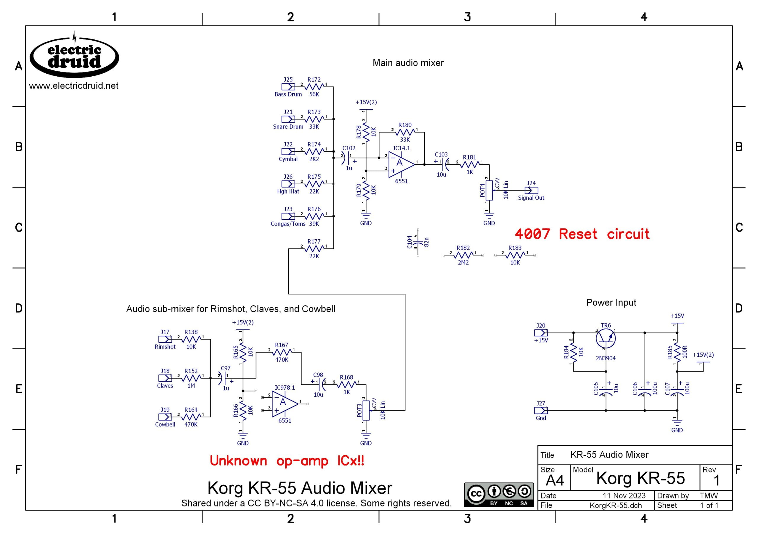
There’s a couple of details I haven’t shown on this schematic. The Rimshot/Claves/Cowbell sub-mixer op-amp doesn’t have a reference on the original schematic, so I don’t know which IC it is part of. I tried to find an IC where only one op-amp was used and there was a suspicious “spare” one left, but didn’t come up with one. I’ve also not shown the 4007-based reset circuit, which just makes sure that the output is muted until things settle down. This article is already long enough, so I’m leaving them alone!
Sources and further details
- Korg KR-55 User Manual
- Korg KR-55 Service Schematic
- Alex Ball’s Korg KR-55 sound samples, used with his permission above. They’re actually from the KR55B, the slightly later “black box” version with a bigger memory, but the voice circuits are the same. Thanks Alex!
If you have any comments or feedback on the article, please post in the comments below. Thanks!
Another top quality article, Tom! Thanks for sharing your in-depth analysis. It’s amazing what they managed to achieve with so few electronic components. -Richie,
Thanks for posting such a detailed description! I’ve made quite a deep dive into the KR-55 recently… a few months ago picked up a ‘for parts’ KR-55 voice PCB that was in a very sorry state with a lot of corrosion on part of the board. Luckily the only failed components were the tantalum caps and dodgy electrolytics – and the output pots needed complete disassembly and clean to get working well.
After getting the voice board functioning, I’m making a sort of clone of the KR-55(and B) using a Raspberry Pico for the control and logic with some support circuitry on protoboard. All in a fairly compact 3d printed enclosure, with some switches, pots, rotary encoder and LCD for user interface. I’m experimenting with MicroPython to see if it’s performant enough for playing the drum patterns – the Pico’s PIO helps with triggering the drum sounds in sync. Still work in progress – the swing function will be interesting to implement.
The ROMs for the KR55 and KR55B are available to download at dbwbp.com/index.php/9-misc/37-synth-eprom-dumps . Using a combination of a hex editor, spreadsheet and terrible Python code I managed to convert the 8 bits + ‘a’, ‘b’, ‘C’ to 11 bits for triggering the voices on the Pico’s GPIO. It’s good to have the schema confirmed. The patterns in the 55 and 55B user manuals are accurate, and I was able to cross reference the pattern names with the 32 byte blocks in the ROM data after working out that the steps in the ROM are in reverse order – looks like the logic board flip-flops count down.
Rimshot/claves/cowbell mixer is shared with the main output mixer – IC8. However it is marked as duplicate IC4 on my PCB. Also the silkscreen for the relevant pot says “Rimshot, Cowbell, Craves”!
Thanks Jas, that’s very interesting! I’d not spotted that the counter counts down, but of course it doesn’t actually make any difference – you can put the data whichever way around you like in the ROM! They must have had some motivation for doing it that way though. Perhaps it makes the logic easier for the 3/4 time and 5/4 time patterns? I’ll have to have a look.