
The Boss Dr Rhythm DR-110 was introduced in 1983 and was the second drum machine Roland had made under the Boss label, following the frighteningly basic DR-55 in 1980. It was also the last drum machine that Boss made before the Dr Rhythm series moved onto digital samples. The Linn Drum (LM-2) was released in 1982, so by this point, analogue drum machines were old tech and everyone wanted digital. But beggars can’t be choosers, and the Dr Ryhthm was definitely aimed at the budget end of the market. Not everyone could splash out $3000 for a Linn Drum, so the DR-110 was a lot more affordable, and that meant it had to be analogue.
The DR-110 is a pretty simple beast soundwise, but that opens up lots of potential for tweaks and mods. It is sonically pretty similar to the TR-606, and has a bit of TR-808 DNA too. The Dr Rhythm includes six sounds and is able to add accents but has no control over sound volume. You can’t change the velocity of a hit on this thing! Too early! The six sounds are Bass Drum, Snare Drum, Cymbal, Open Hihat, Closed Hihat, and Handclap. In the User Manual, Boss list “Accent” as a sound source, but that’s pretty misleading since it doesn’t make any sound of its own. You also can’t set the volume of individual sounds, you can’t pan the sounds, and you’ve got no individual outputs. There’s plenty of additions we could make!
Boss Dr Rhythm DR-110 Schematic
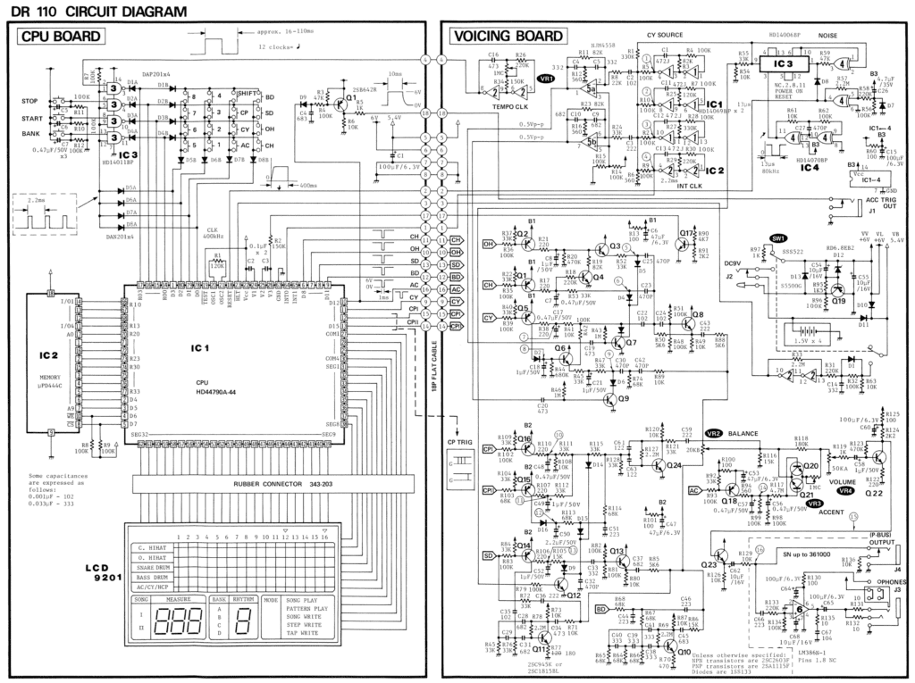
The schematic is divided into two areas, following the division of the circuit into two separate PCBs. Sensibly, Boss have put the digital side on one board and the analog audio-producing stuff on a completely separate PCB. That will help prevent noise getting from one to the other. There’s an 18-pin connector joining the two boards, which takes power (6V, 5.4V, and two pins for ground), eight trigger signals, and six other signals.
CPU Board
The CPU board does all the rhythm programming stuff, scans the buttons, and runs the LCD display. The actual CPU is a 4-bit Hitachi HD44790A-44 running at 400KHz! Yes, really! Feel the raw power! It stores the patterns on an external RAM chip and generates the triggers for the drum voices. The RAM is a 1024 x 4-bit memory, so a massive 512 bytes.
Interestingly, the CPU doesn’t generate the tempo. The Tempo Clock is on the analogue board and feeds a clock signal to the CPU. It runs at a rate of 12PPQN from 9.09Hz to 62.5Hz, which is 45 to 312BPM. Presumably this clock starts an interrupt on the CPU and tells it to produce the next set of voices triggers.
The CPU generates eight channels of trigger signals. These are inverted logic, normally-high-going-low rather than the reverse. The Open and Closed Hihats, Cymbal, Bass Drum, Snare Drum, and Accent have a trigger each, and the Handclap has two trigger signals. We’ll deal with that when we come to it.
Aside from generating triggers, the uP has no part in the actual synthesis of the sounds, so we’re going to ignore it from here on in.
Voicing board
This is where the fun stuff happens! There are basically two types of sounds in the DR-110: tuned drums and noise-based sounds. The tuned drums are the kick / bass drum (BD) and the body of the snare drum (SD). The noise-based sounds includes the open and closed hi-hats (OH, CH), the cymbal sound (CY), and the handclap (HCP).
Before we look at the sounds themselves, let’s look at some of the sources and elements that are used to create them – the Noise Generator, the Cymbal Sound Generator, and the Roland Swing VCA.
Noise Generator and Cymbal Sound Generator
The DR-110 has a simple LFSR noise generator. We looked at hardware LFSRs in more detail in the TR909 noise generator article. Unlike the TR-909 which uses two 4006 shift register chips, the DR-110 only uses one, so it’s an 18-stage LFSR. It’s clocked at 80KHz and taps 13 and 18 are XOR’d together to go back into the beginning of the register. That means the noise has a repetition rate of 3.2 seconds which isn’t very good, but since percussion sounds tend to be brief, perhaps it doesn’t matter in this application. Only the snare uses the white noise generator on its own. The HiHats and main Cymbal voice both use the output from a special “Cymbal Sound Generator”. This mixes the white noise with the output from four square wave generators to create a more metallic noise.
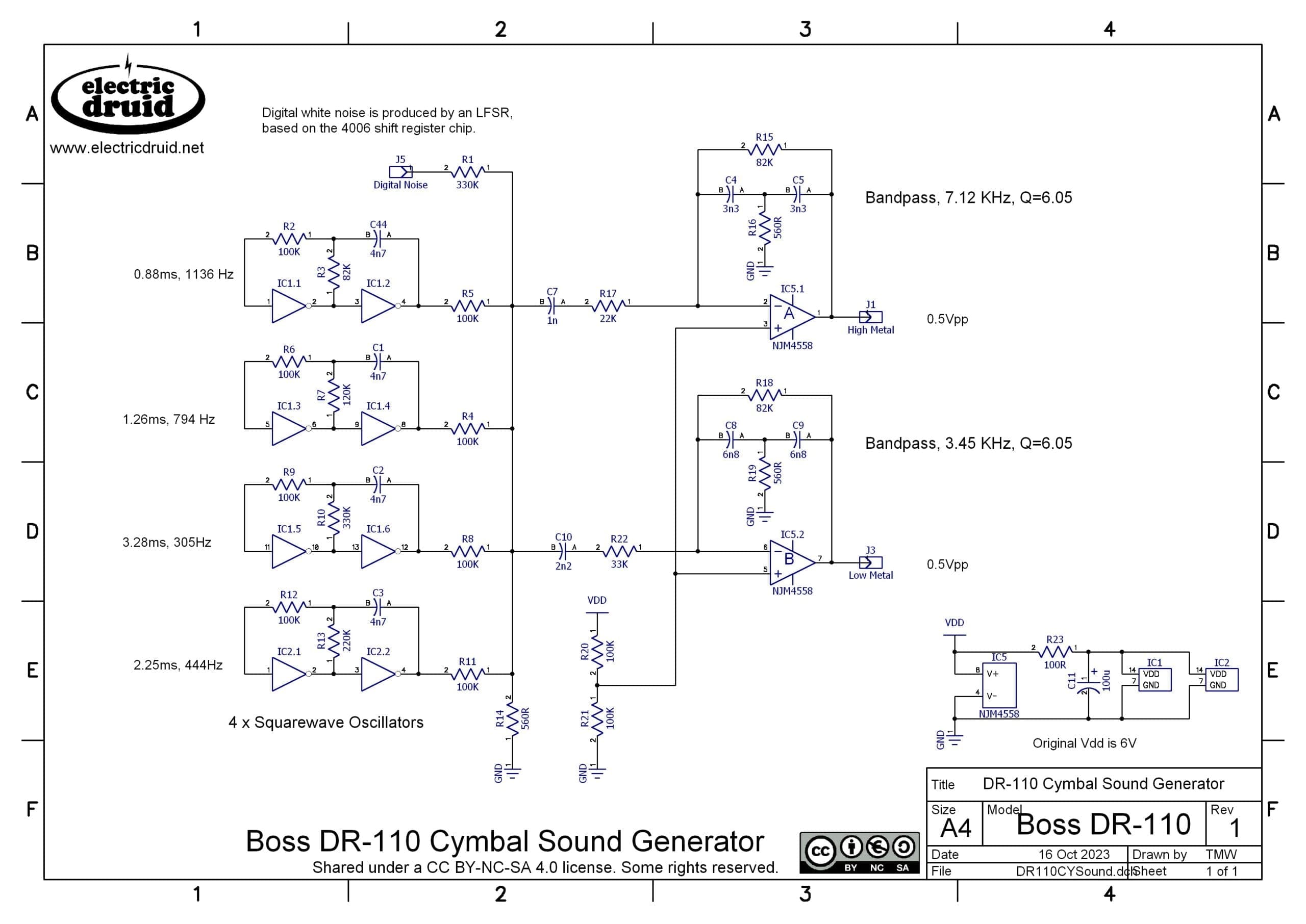
The four square waves are configured to a particular set of non-related frequencies (305Hz, 444Hz, 794Hz, 1136Hz). The service manual claims “Interrelations between frequencies are so critical that slight deviation of one frequency can cause beat sound or distortion”. It then goes on to say that the caps should be 5% tolerance which is pretty close for caps, but means that even the lowest of the frequencies could be +/-15Hz. So “close” is close enough, and we don’t need to worry too much.
Since metallic sounds like bells often have inharmonic elements, the sonic effect of adding these unrelated frequencies is to give a metallic noise. The resulting metallic noise is fed to two different bandpass filters, to produce what we’ll call the Low Metal and High Metal signals. These have the following responses:

Roland provide equations for the centre frequency and Q (resonance) of this type of filter in the TR-808 service notes:
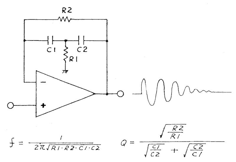
Using this we can calculate the figures shown on the schematic above. The Low Metal filter is at 3.45KHz and the High Metal filter is at 7.12KHz, and both have a Q of 6.05.
Notice that the Service Notes filter shows the input going to the op-amp’s +ve input. This gives a “resonant” or “peaking” response, which is mostly flat, but produces significant gain at the resonant frequency. Feeding the input to the -ve input, as in the cymbal sound generator, has a different effect. It produces a resonant lowpass response. In the schematic above, this is further shaped by the C7 and C10 input capacitors which provide a highpass rolloff. This is why the “bandpass” shape has unequal slopes, 6dB/oct for the highpass, 12dB/oct for the lowpass.
Roland swing type VCA
The Roland “swing” type VCA is about the simplest VCA design there is. It’s not hi-fi by any stretch, but it’s ok for simple percussion voices. It tends to feed the envelope signal through to the output, so there’s a DC thump unless it’s subsequently highpass filtered. It turns up in many of their instruments, being pressed into service in the TR-909, for example.
Why’s it called the swing type VCA? I have no idea, but that’s what Roland/Boss call it, so that’s what it’s called.
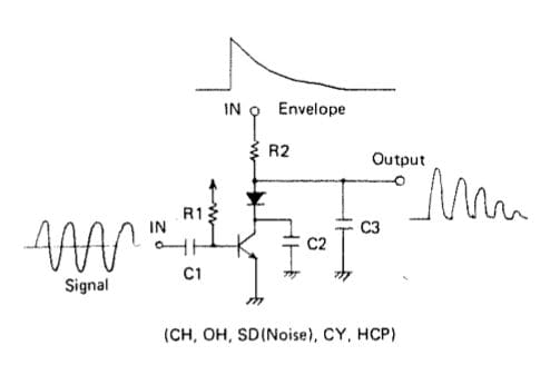
We’ve looked at it before (I used it in my Vintage Hiss, Crackle, and Pop circuit, for example), and it’s very simple, so I’ll be brief. Rather than using an envelope voltage to set the level of an audio signal, instead this uses an audio signal to control the output of an envelope. Depending on the resistor values used, this can be more or less abrupt, but in many cases, it is simply switching the envelope output on or off – slicing it up at the frequency of the audio. This is also the case where the audio is a signal with only two levels, like a square wave or the random pulses from an LFSR white noise generator.
How it works is that R2 and the transistor effectively form a voltage divider for the Envelope signal present at the Envelope Input. Depending on the amount of base current, the transistor will be more or less switched on, and its effective resistance will vary, changing the ratio of the voltage divider, just like someone tweaking a volume control.
One remarkable thing about this swing type VCA is that it can be used by several circuits simultaneously and independently. This means that (for example) the VCA based on Q12 is used by the handclap sound twice and the snare sound once without those signals getting mixed together! This feature is widely used in the schematics to save even more parts. It’s extremely elegant for such a basic circuit.
Bass Drum
The Bass Drum is one of the simplest instruments in the DR-110 which is why we’re starting with this one! It’s a damped oscillator circuit. The idea of this is that the circuit wants to oscillate at a particular frequency, but doesn’t have quite enough gain to continue oscillating. If you “hit” it with a trigger of some kind, it will oscillate for a short while, but the sound soon dies away to nothing. You can adjust the decay of the sound by changing the amount of gain the circuit has, and you can tune the oscillation frequency too, but you can’t adjust these independently. For a given amount of gain lowering the frequency makes the sound much longer, and raising the pitch makes the sound much shorter. If you consider the decay in terms of “number of cycles before silence” then this makes sense. This behaviour is also typical of many physical sound sources, so it’s not altogether a bad thing.
The final variable in terms of the sound is what the actual trigger looks or sounds like. A single pulse produces a different attack to a short burst of noise, for example. This is used in the DR-110, so we’ll see examples of both.
Roland offer a “typical” schematic for this circuit in the service manual:
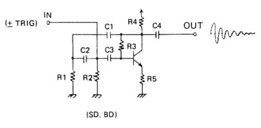
The DR-110 Bass Drum circuit adds an extra RC pair like R1/C2 to the left, but is otherwise exactly like this typical schematic. There’s a couple of other details, one of which is that the trigger pulse is lowpass filtered before being used to trigger the drum, and the other is that the filtered trigger pulse is also fed to the output to add to the attack of the sound. It gives a bit of an untuned “whack” before the main “thump” of the sound’s body.
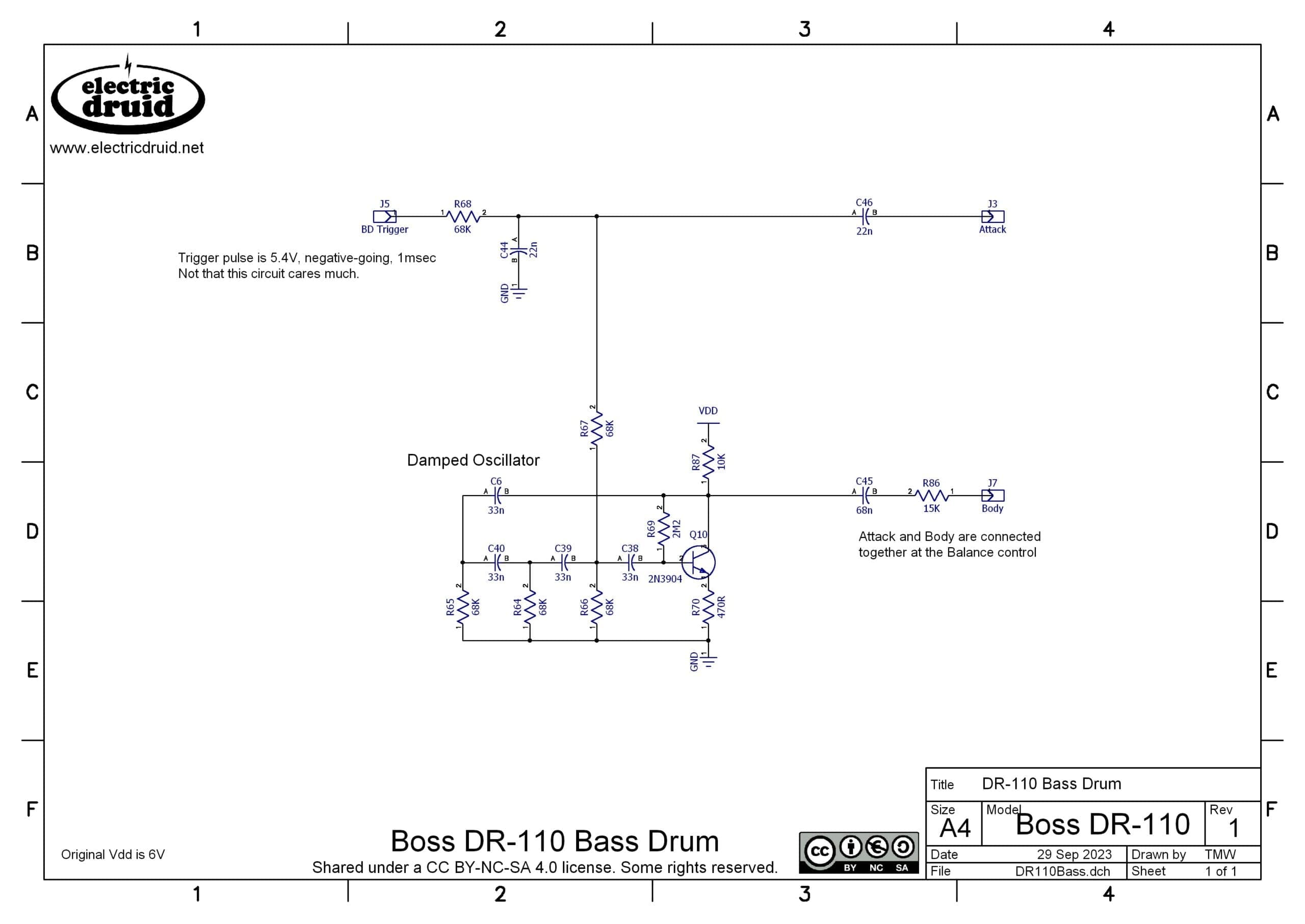
Note that you can do a very similar thing with an op-amp instead of a transistor. The DR-110 ran on batteries and was low voltage and low cost, so a single transistor was a better choice.
Snare Drum
The snare drum is a bit more complicated than the bass drum, since it adds a third element. As well as the damped oscillator creating a tuned sound for the body of the drum, and the trigger pulse providing some attack, we also have a VCA-shaped digital noise burst to provide the “snap” of the snare wires.
When the SD Trigger goes low, Q14 switches on and R106/220R is pulled high. This charges C52/1µF. The values are chosen so the 1µF cap is completely charged during the 1msec trigger pulse. As soon as the trigger pulse ends, C52 starts to discharge more slowly through R105/15K. This provides a very simple decay envelope. This envelope is then switched on and off by the Digital Noise signal fed to the base of Q12, creating an enveloped noise burst. This goes to the output via C33/3n3 and the buffer built around Q17.
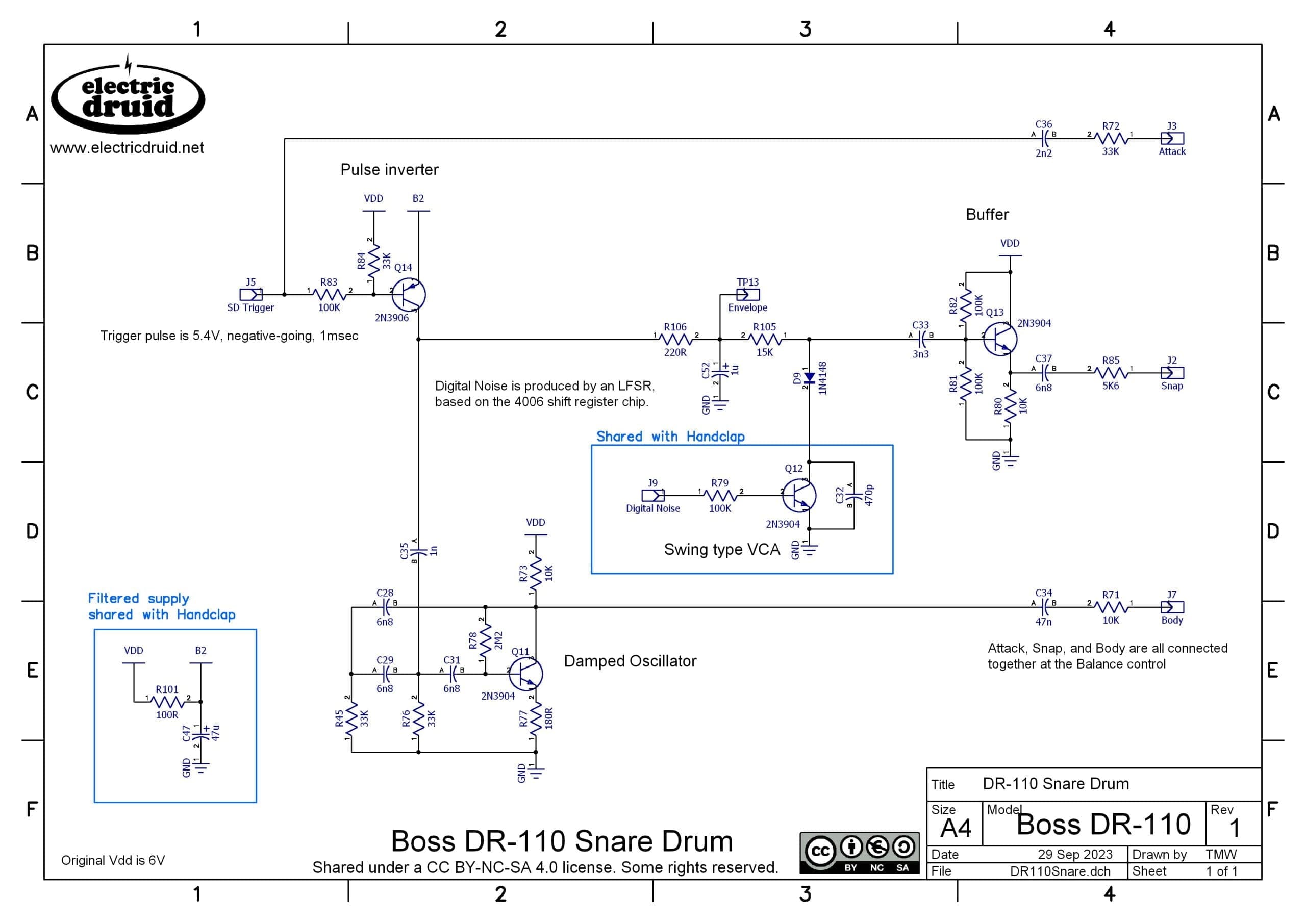
The Body of the sound is created with the same damped oscillator we’ve just looked at with the bass drum. This one is more like the “typical” version we were offered. I haven’t really worked out why Roland used a third set of RC phase shift components for the bass drum but not the snare.
It’s also worth noticing that the trigger pulse is not lowpass filtered in this case, but is used directly for the Attack, so the snare drum has a sharper attack than the bass.
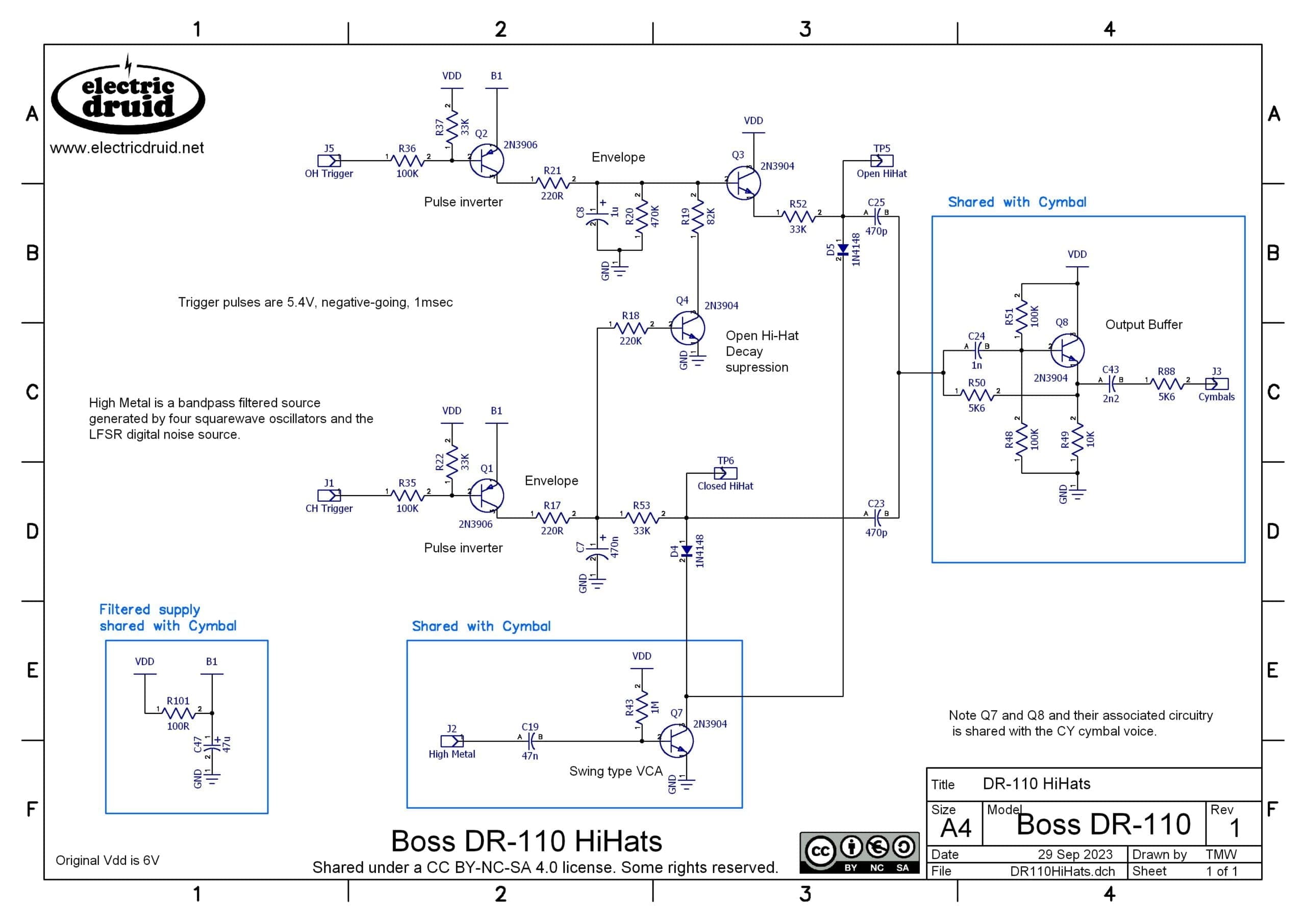
Open and Closed HiHats
The hi-hats are interesting and a bit different! Both the Open and Closed Hi-Hat are based on the High Metal signal from the cymbal sound generator, but the open hat has a much longer decay time than the closed hat (as you’d expect). The closed hat can also shut off the decay of the open hat, which offers a third possible decay time.
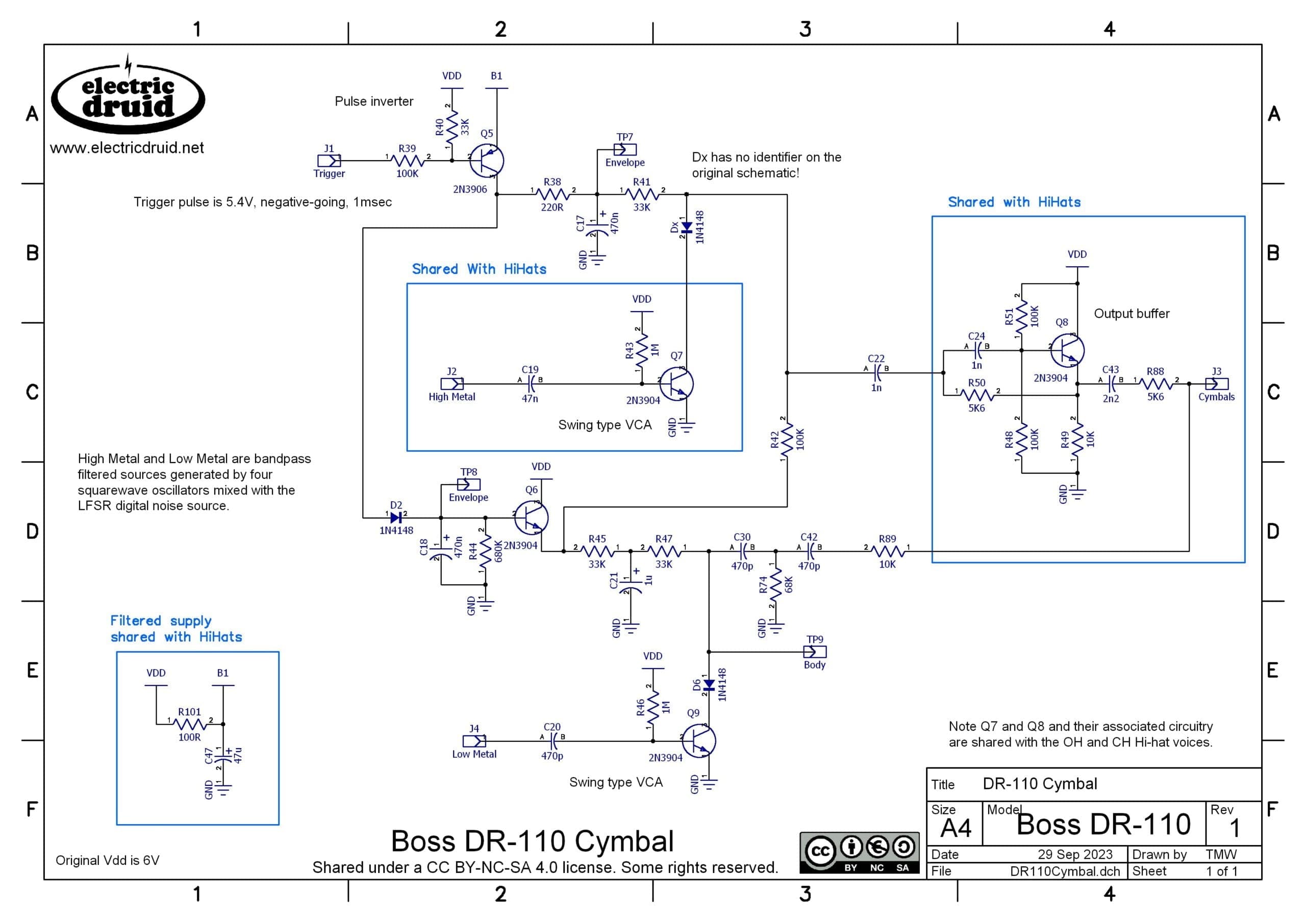
Cymbal
The main Cymbal sound is much like the hi-hats, except in this case, we have two elements, with the initial “ting” of the cymbal created using the High Metal signal, and the longer tail of the cymbal sound created using the Low Metal signal. Both elements are created the same way, however: A simple decay envelope, shaped using a swing type VCA being fed with a filtered metallic noise signal.
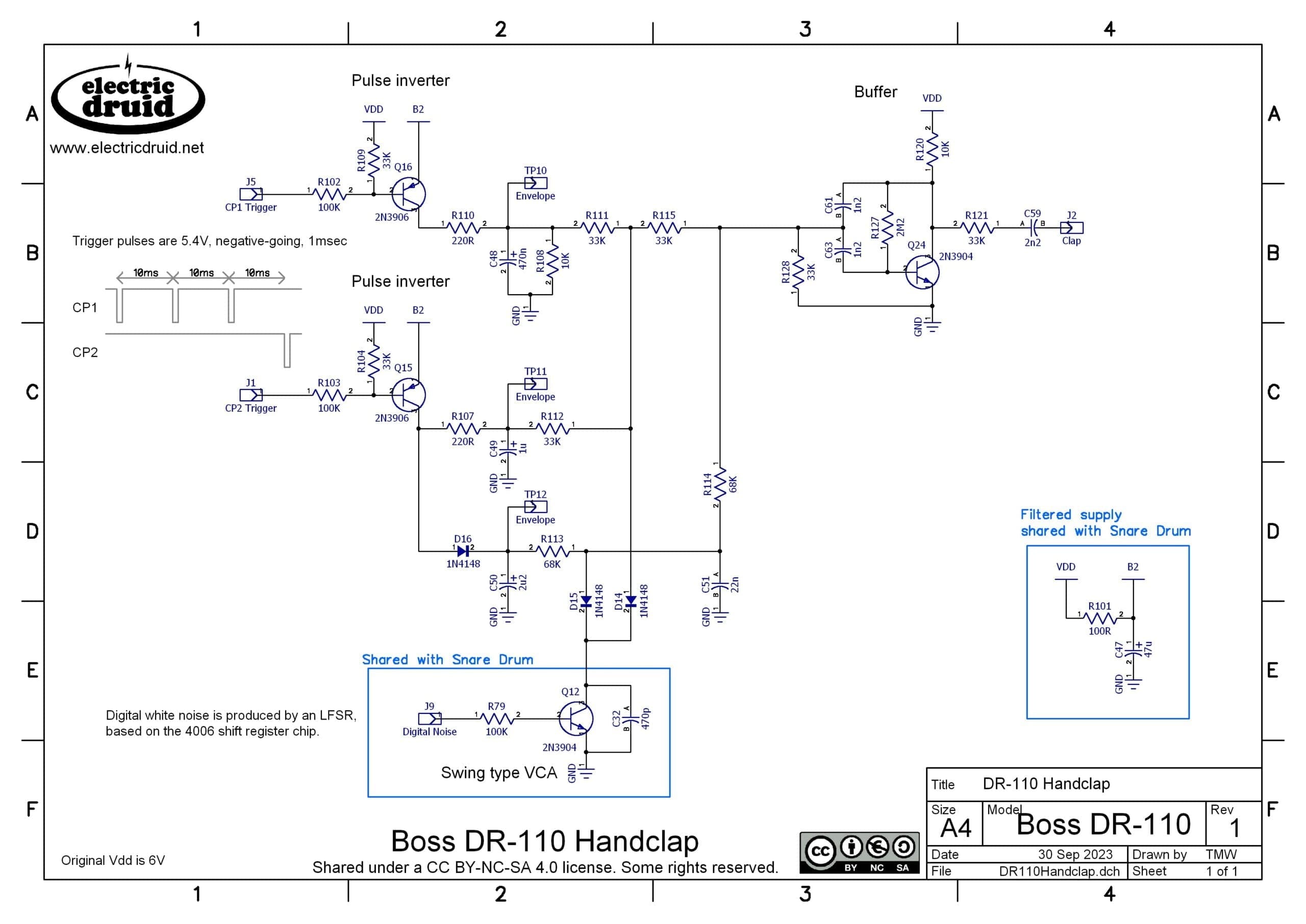
Handclap
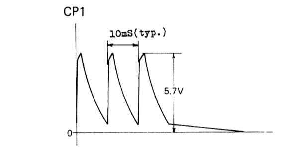
The handclap circuit is an interesting sound because unlike the others, it uses the processor to some extent. The processor doesn’t create any of the actual sound, but it creates two separate sets of triggers, with quite specific timings. One of these (CP1) is used to create the sound of several individual claps, so the sound is a group clapping, not a single person. The CP2 trigger is then used to create an impression of a reverberation dying away after the initial burst of claps.
Again, the triggers are shaped into simple decay envelopes, although in the case of the CP1 multiple trigger, this creates a multiple-hit envelope, shown below in an image from the service manual. Even this is not the complete story since another decay derived from CP2 is also added to this envelope, so the final sound is four separate hits.
The envelopes are fed to a swing type VCA and used to shape the digital white noise source. The result is then fed to a bandpass filter. This is the same “bridged-T” design we saw in the Cymbal Sound Generator, except this time the active element is a transistor instead of an op-amp. The bandpass is centred around 910Hz.
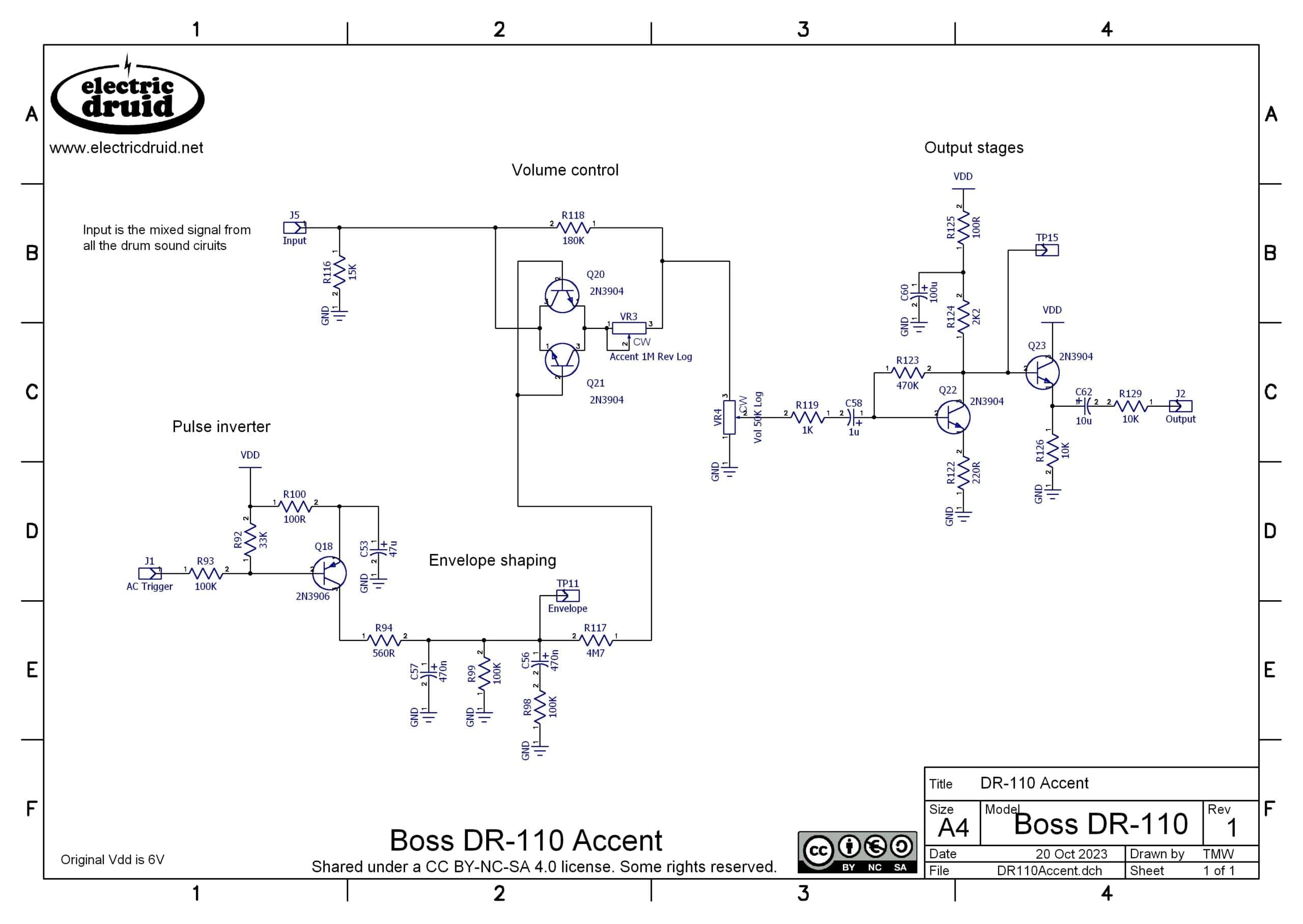
Accent
The accent trigger is used to create a short decay envelope which controls the overall output level. The service manual shows an envelope time of 120msecs for the accent decay. This envelope is sent to a VCA based on Q20 and Q21. While this VCA is slightly more complex than the single transistor swing-type VCA, it still introduces significant distortion.
Other details
One thing to note is that the schematics are liberally scattered with “TP” markers. These are Test Points, and are labelled as Check Points in the original schematics. The service manual provides a useful table showing the decay times and levels of many of the sounds’ envelopes.
| Name | Test Point | Decay Time | Level V |
| Open Hihat | 5 | 700ms | 6V |
| Closed Hihat | 6 | 80ms | 6V |
| Cymbal Attack/High | 7 | 60ms | 6V |
| Cymbal Body/High | 8 | 900ms | 6V |
| Cymbal Body/Low | 9 | 1.4s | 2.7V |
| Handclap (last clap) | 11 | 140ms | 5V |
| Handclap “reverb” | 12 | 700ms | 5V |
| Snare Snap | 13 | 100ms | 5.7V |
| Accent | 14 | 120ms | 5.7V |
Sources and further details
- Boss Dr Ryhthm DR-110 User Manual
- Boss Dr Ryhthm DR-110 Service Manual
- Synth.in DR-110 sound samples
Richard Curcio’s website has all sorts of interesting stuff, but the following article was very helpful for me to get my head around the DR-110:
The Delptronics LDB-1 and LDB-1se circuits are (mostly!) a modernised take on the DR-110, and the schematics for them are very elegant and show how to do a lot with not a lot. If you’ve enjoyed this article, you should definitely take a look.
If you have any comments or feedback on the article, please post in the comments below. Thanks!
Wow, thank you for this! Excellent brain-food!
what a brilliant article thanks for your efforts ! presuming this thing could produce the sounds in parallel (ie two or more simultaneously), do you think the extra rc phase shift on the bass drum might be to prevent phase correlation issues between the bass and snare when overlapping ? just my two bob!