
The TR-909 uses a hardware implementation of an LFSR as its noise generator. We’ve dealt with LFSR noise generators in a few other articles, but we’ve only looked at firmware implementations, so it might be fun to see how the same thing is done in hardware.
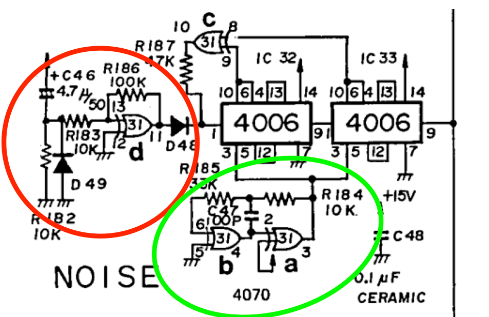
The circuit is composed of three parts; the shift register itself, a clock, and a start-up circuit. Firstly, here’s the whole thing:

Three ICs are used, two 4006 18-stage shift registers, and a 4070 quad-XOR gate. The two 4006 chips provide a total of 36 stages of shift register (18 in each chip) but only 31 stages are used. The output is taken from the 36th stage, but this is simply a delayed copy of the output at the 31st stage. Incidentally, the service manual for the TR-909 claims that the noise generator is a 32-stage design, but this is not actually true. It’s definitely a 31-stage shift register. Here’s what they say about it:
NOISE
This is a quasi-random noise generator having two shift registers (IC32, IC33) connected in cascade making up 32 stages. Chaining of 32 stages provides a longer interval between the beginning and the end of shift cycles. This means that the frequency changes occurring at end/start points of shifting cycle are made less noticeable to the human ear. Two Ex-OR gates of IC31 clock the shift registers at a higher frequency, allowing them to create noises contain favourable higher frequency contents. On power-up a trigger is applied into pin1 of IC32 via D48 for starting running.
Roland TR-909 Service Manual, page 6
The clock circuit uses two of the XOR gates and is circled in green below. The start-up circuit uses another XOR gate and is circled in red. The rest of the circuit is the real guts of the noise generator, the shift register. We’ll look at each part in turn, but let’s start with the shift register.
The shift register
The shift register is based on two CD4006 18-stage chips. The 4006 does not allow access to every stage of the shift register. That would require too many pins. Instead, the chip provides various blocks of four shifts, plus a couple of extra single shift sections. Using these you can build shift registers of 4, 5, 8, 9, 10, 12, 13, 14, 16, 17, or 18 bits. Here’s a diagram of the chip.

The first and second 4006 chips are wired up in exactly the same way. The top row is the first chip (on the left in the schematic) and the bottom row is the second chip (on the right in the schematic). Two feedback taps are taken to an XOR gate. The gate’s output is fed back into the input of the shift register at pin 1.

For a 31-stage register there are various combinations of taps that give the maximal length sequence of bits (2^31 -1 = 2,147,483,647 bits before the sequence repeats). Some of these require four taps, but it’s usually more efficient to use the few options that only require two taps. There are eight of these sequences, four basic ones, and four “mirror images”:
- 31, 28
- 31, 25
- 31, 24
- 31 ,18
Note that if (N, M) is a maximal length set of taps and N > M, then (N, N-M) is as well. This gives us four more options:
- 31, 3
- 31, 6
- 31, 7
- 31, 13
The TR-909 uses one of these ‘mirror’ options, 31 and 13.
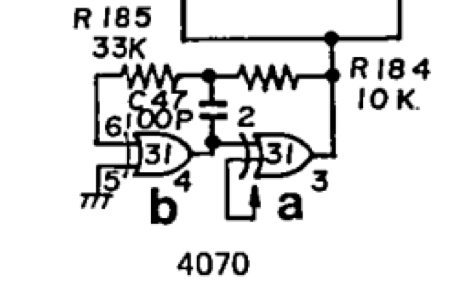
The clock circuit
The two shift register chips are clocked from a basic clock circuit built from two of the XOR gates. It operates at a frequency of roughly 300KHz, although this can vary significantly depending on the brand of 4070 chip used, and the actual value of the 100pF capacitor (which could easily have a +/-20% tolerance). Given that the frequency is so high, these variations make no audible difference whatsoever. The noise spectrum will be flat out to 100KHz or beyond, way further than the 20-25KHz we can hear. The sequence is long enough that even at this rate, it will not repeat for almost two hours.
The start-up circuit
The start-up circuit is designed to make sure that the input is high when the power is applied. The XOR LFSR design will lock up if the entire shift register is filled with zeros (since both feedback bits will be zero, the feedback will be zero, and the situation cannot change). The start-up circuit avoids this problem and holds the shift register input high for about 20-30msecs initially. This is clearly easily long enough to fill the shift register with ones (half a millisecond would have been ample).
Can I build one?
The CD4006 is no longer available, and although there are a few other chips you could probably use instead with a bit of work, it doesn’t really make sense if you can copy exactly the same thing in firmware on a single smaller chip that costs much less. A firmware version can use the same length register and the same two taps and will produce exactly the same sequence of random bits (not that you’d ever know…this is white noise, after all). Since the AVR family chips only use a single clock cycle per instruction (rather than the four that the PIC chips require) they might be a better choice for this job. However, I was able to knock up a quick proof-of-concept on a PIC 12F1612 that ran with an output rate of 285KHz. This is within about 5% of the 300KHz typical rate for the TR-909, and definitely within the tolerances of the capacitor in the hardware version.
For completeness of your excellent work, as of my post here — http://electro-music.com/forum/topic-69910.html — a good Russian chip K176IR10 equivalent to CD4006 is available.
Thanks Robert.
hi! i am new to this (diy) modular world, but i dont think white noise is always the same white noise and so i ordered this russion version cause i just like to try to built it. where do i get more information on building it ? thanks for this nice article.
I haven’t really got any more information I can give you past what is already in the article. There’s a full circuit diagram given, and an explanation of the function of the chips for debugging. Obviously a PCB or strip board layout would help, but I don’t have one, I’m afraid. Sorry!
You never know though, a google search for “909 noise generator” might turn up someone who’s built one who could help a bit more.
Good luck!