Description
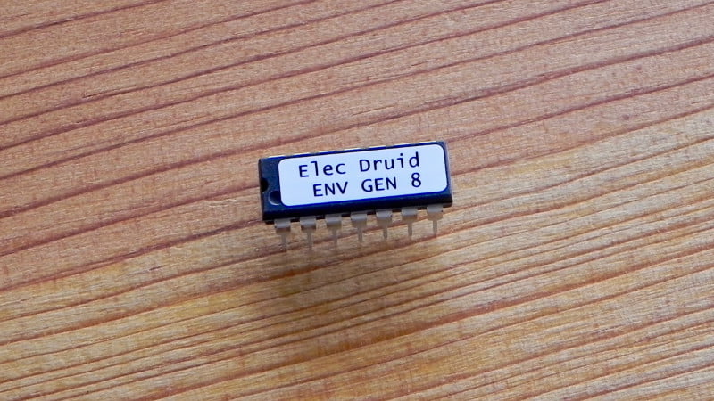
This chip is a comprehensive upgrade of the previous generation of Electric Druid voltage controlled envelope generator chips, the VCADSR 7B and LOOPENV 1B. The VCADSR had both GATE and TRIGGER inputs, and the LOOPENV featured a MODE CV that allows selection of normal ADSR, Gated looping, or full LFO-style Looping modes. This chip combines the features of both onto a single chip, and removes the need for a crystal and reconstruction filter. It also improves the output sample rate to 31.25KHz, improves the envelope table resolution, and uses a multiplying DAC for the output, which allows full analog Level CV control without any loss of resolution or calculation errors.
The ENVGEN8C chip keeps the other features of the originals, like full voltage control over all parameters (Attack, Decay, Sustain, and Release), and the TIME CV which shortens the overall time of the whole envelope. The TIME CV makes an excellent modulation input for either envelope modulation or LFO frequency modulation. It also adds a PUNCH input which holds the maximum level for a few milliseconds before starting the Decay stage. This is very useful for adding extra punch to short percussive envelopes.
Download Electric Druid EnvGen8C datasheet
The datasheet includes example circuit diagrams, example waveforms, and the chip pinout diagram.
If you’d like to program your own chip for personal use, code and further details are available over on the original article about the new Druid chips.
Modular Synth Envelope Generator design
Here’s an additional schematic showing one way the chip could be used for a modular synth envelope generator. This includes input/output protection and CV inputs for various parameters. Hopefully you will find it inspiring!
ENVGEN8 modular synth envelope generator schematics


ehk506 (verified owner) –
Absolutely love this chip, ridiculously easy to use and beautify versatile. 10/10 would ENVGEN8 again
David –
absolutely very great chip!!
but there might be a bug, i’m not shure.
what happens: pin3 is grounded for adsr-mode. but when i power up the chip, its always in gated looping mode…
when i apply first 5v to pin3, then go back to 0v, then it will go into adsr mode. why is that?
is there a way around it, or am i doing something wrong?
cheers to your very nice chips! very good work!!
thanks
David
Tom Wiltshire –
Yes, I think this is “normal”. It happens because currently the chip only responds to *changes* on the pin, so until something is altered, it doesn’t reset the variables.
I’ve got one other minor tweak to release for this code, so there’ll be a ENVGEN8B along soon, and I’ll make sure to check this out and fix it while I’m doing it.
Thanks for the pointer – the more people there are spotting stuff like this, the better the code can get.
Gunnar –
I also have this PIN3 “problem”
When I power up my system with Normal ADSR mode (grounded) selected I have no signal coming out. I first have to change modes then everything works fine.
When I power up with Gated Looping or LFO/Looping mode selected everything works fine from the beginning .
Is an update to ENVGEN8B already available?
thanks,
Gunnar
Tom Wiltshire –
Yes, it is. ENVGEN8C fixes this problem and another minor bug where the chip wouldn’t power up correctly if the Gate was high (which is an over-voltage condition – not good!).
We’ll have the new chips in stock and the updated code online shortly.
Gunnar (verified owner) –
i changed the old ENVGEN8 in my module to the new ENVGEN8C and everything works fine now. Thank you.
What to do with the old chip? I don’t have the hardware (and knowledge) to flash it. But it would be nice to use it in another project.
Is there a workaround for the PIN3 problem?
Can we get 5v to pin 3 on module startup which then discharges (capacitor). Or a transistor switch?
Filip Woźniak (verified owner) –
Hi, can I use 100k pots instead of 10k?
Tom Wiltshire –
Yes, the pots are wired as voltage dividers, so the chip isn’t too fussy about the value. I’ve tried various things from 100K-10K without problems.
Goncalo –
Hi, first thx for the great work, im a big fan! I have a question about disableing cv level, why this big cap 100uf to ground? Thanks in advance
Tom Wiltshire –
The Level CV input supplies the reference voltage to the on-chip DAC, so any noise on that CV input will go straight through to the output. Since +5V supplies are often quite noisy, the 330R/100uF is acting as a filter to help remove any power supply noise. To be honest, a 100nF ceramic cap in parallel with the 100uF to reduce high frequency noise would be a good idea too, as a “best practice” solution.
However, if you’ve got a nice quiet low impedance voltage source that you can use instead, you can drop the filter and connect it directly to the Level CV.
Note also that it only needs to be between the supply voltages of the EnvGen chip itself (so typically from 0-5V, although you can also run the chip on 3.3V or less). In the datasheet circuit, I have Level CV tied to 5V, so we get a 5V envelope, which is then reduced with a voltage divider before going to the VCA. An alternative (and equivalent) approach would be to tie the Level CV to a 2V source, and then the envelope would already be correctly scaled when it left the chip and the 15K/10K divider would not be necessary.
Jerker Lindborg (verified owner) –
Hi!
I just got my 10 ENVGENs and are about to get me a separate voltage regulator to step down to 5V.
What I wonder is how much “over voltage” the ENVGEN can handle as the regulator has a specification of ±4%.
Cheers from Sweden!
Tom Wiltshire –
The ENVGEN8 chip will run with a voltage anywhere from 1.8V to 5.5V, so if your regulator was +/-10%, you’d still be ok.
James (verified owner) –
Tom,
Any idea when you will have the Full schematic with all the controls available? I bought 4 of these to make some dual vca modules and only need the schematic.
Thanks
Tom Wiltshire –
I’ll try and get it finished off – it’s certainly been kicking around long enough. Thanks for the reminder. Knowing that someone is waiting provides a useful dose of motivation!
Yoeri (verified owner) –
I am very excited to go and use this beautiful chip. Would be great to see the updated schematics though. Hows that for a useful dose of motivation huh 😉
Thank you for the great work, keep it up!
yoeri (verified owner) –
Just had a bright idea … or not… u tell me. Could we treat the time cv and level cv in the same way that frequency cv input is drawn in the vclfo10 schematic? as its using the opamp to combine cv input and regular 10k pot control? thanks in advance!
Tom Wiltshire –
Yes, that will work. You’ll need to add a second unity-gain inverting op-amp to re-flip the signals because the ENVGEN8 chip doesn’t have the option to invert CVs internally.
Yoeri –
promise makes debt 😉 where are the updated schematics?
Tom Wiltshire –
Ok, ok! I’ve uploaded them! 😉 Linked above.
Yoeri –
Thank you so much for the update!
Kalle –
Hey 🙂
Super nice things first of all!!!
I was thinkin can u add cv inputs in serial with the potentiometers?! so u get the cv control over the different stages?!
Tom Wiltshire –
Yes, you can. Have a look at the VCDO datasheet for some ideas. Note that the CV inputs on the ENVGEN8C aren’t inverting though. I might fix that one day on an ENVGEN9 version.
Richard –
What is the filtering like on these? Having learnt that unsynchronised multiple class d amplifiers connected together are liable to produce a lovely bunch of warbling difference tone switching noise (-there are now ferrites everywhere….), if I had 4 or 5 of these together would I risk a similar situation?
Tom Wiltshire –
The output from the chip is straight out of the DAC at 31.25KHz, so “how good is the filtering?” is up to you!
If you were going to add together the outputs of several ENVGEN8s directly, then perhaps some external filtering to remove any little steps would be a sensible approach. The modular synth example circuit includes a filter, for example. You’d have to try it to know for sure.
Ben (verified owner) –
Really nice chip. So many possibilities for envelope generation. I would like to add it as an envelope generator to the Moog Werkstatt which has a more limited envelope. I can get a +9V and -9V tap from the Werkstatt as well as a +12V but there is no -12V tap. Is there a relatively simple way adapt the modular schematic to work with a + and -9V supply instead of a + and -12V or would that sacrifice too much in terms of op amp performance or create other issues?
Tom Wiltshire –
The Modular Synth Envelope Schematic should work fine with +/-9V without any changes. The bipolar supply is only really used for the op-amps, and they’re not fussy. Everything else is run from the +5V supply. Good luck!
Update: Please note I’ve also changed the filter cap values in the output op-amps for the Modular Synth Schematic. The little 47p’s stabilise the op-amp but don’t provide any filtering. For better noise performance, use 1n instead.
Ben (verified owner) –
Thanks Tom. Works great! I need to get an external trigger to use the envelope in normal mode, but I’m already finding lots of interesting uses for module by plugging it in to the werkstatt in looping mode.
Tom Wiltshire –
If you’ve only got a Gate and don’t need to re-trigger with the gate high, just tie the Gate and Trigger pins on the EnvGen8 together. Then it behaves as you’d expect.
Ben (verified owner) –
Thanks for the update. I have noticed some noise so I will swap out those caps.
Ben (verified owner) –
If anyone else out there is thinking about building the Modular Synth circuit for the Werkstatt (CV expander, with power coming from the synth) I highly recommend adding a fine tune control to your module. You just need two 150K resistors, a 10K pot and a 3.5mm jack.
This video gives you the gist of the fine tune mod https://www.youtube.com/watch?v=0k0KhltoUIQ
We can use the +/-9V to power the module and for the mod. In this case the middle pin of the pot goes to the tip connector on your jack and ground goes to ground (the video shows the patch bay which doesn’t have a ground).
If you put the envelope in looping mode and plug it in to the VCF audio in you can use it as a kind of second oscillator which is weird and interesting because the VCF audio in should disable the internal oscillator of the Werkstatt but for some reason with an envelope signal going into it you can modulate the internal oscillator. This is where the fine tune control really comes into its own. You can really dial in on the pulsing rhythm that comes from the slight de-tuning of the oscillator in relation to the envelope signal that is modulating it.
I don’t have the gear to try this yet but I think it might also be possible to keytrack to two oscillators to some degree by using the ‘time’ input on the module.
Bas (verified owner) –
On page 1 of the example circuit the diodes are marked as 1N4148. Can i assume the unmarked diodes on sheet 2 to be of the same kind?
Tom Wiltshire –
Yep! Sorry, should have marked them all as 1N4148.
BTW, watch out for the Eurorack power connector polarity. Someone pointed out that I had some of them back to front, and I haven’t checked them all.
Nikolai Chigrin (verified owner) –
The first circuit i build was the very simple one on the bottom of the datasheet and it worked perfectly fine! For some reason it stopped working from one second to the other and the output was at a constant 4,98V with 0,01-0,02V change if i triggered the gate. I was confused and checked the circuit, but everything was at the same place as before. I’ve tried to rebuild the same circuit on another breadboard but still have the same problem. I’ve tried your modular synth schematic aswell, but i am still running into the same problem…
Do you maybe know what else i can try? I’m new in the world of electronics and can’t find any other sheets on this chip or anything else…
Thank you very much!
yoeri –
I’ve built my envelope generator and it seems like the ADSR funtion doesnt work. after troubleshooting i found that my +5v power supply delivers +5.2v… so pin 5 (gate cv) allso recieves this voltage. could this be why it wont respond to a incoming gate?
thanks you in advance, you guys are great!
yoeri –
Sorry, please ignore previous post. i think i got it… “trigger jack should be connected such that the trig input connects to norm trig when no jack is inserted” in other words… gate wont work if there is no +5v to trigger input pin 6. i am glad i allready used a switching contact jack…should make it an easy fix.
Tom Wiltshire –
Yep, that’ll be it. If you’re using Gate-only, the Trigger and Gate pins on the ENVGEN need connecting together. Otherwise the envelope never triggers.
roland klinkenberg (verified owner) –
I’m using this Envgen8 IC in my Sequencer Aux card for the Buchla 208 and it’s absolutely fantastic.
The Envelope Level control really opens up the creative possibilities of the envelope concept.
Also, Loop & LFO mode are awesome! There’s so much you can do with this chip….
Miquel (verified owner) –
Hi, I’m using the Env Gen 8C in a synth project and I have a couple of questions: I’m afraid that the 5v output won’t be enough for my filter and vca. Should I add an extra amplifier stage or is it possible to tweak the output opamp in the schematic to give it more gain?
Also, I want to use only one pot for decay/release. Should I just tie together pins 9 and 11 or should I use an extra resistor/capacitor to go to the pot wiper?
Many thanks!
Tom Wiltshire –
Looking at the Modular Synth Schematics for the chip, it’d be easy to add a little gain to the output buffer. Just add a resistor from IC2.1 pin 2 (-ve input) down to ground to convert it into an non-inverting amp. 100K will give you gain of two. You may not need so much, and increasing the resistor to ground so it is larger than 100K will reduce the gain.
For the Decay/Release, yes, you should be fine to tie the two pins together.