
It’s been around ten years since I developed the original Druid NOISE 1B chip to produce good quality white noise. Finally it gets an update, and the new NOISE2 chip can produce pink noise as well as white noise, so there’s no need for external “pinking” filters.

Here’s what it sounds like, white noise and pink noise:
Here’s the spectrums for the two outputs. Note the scales on these two graphs are different, so you can’t compare one to the other directly…sorry!
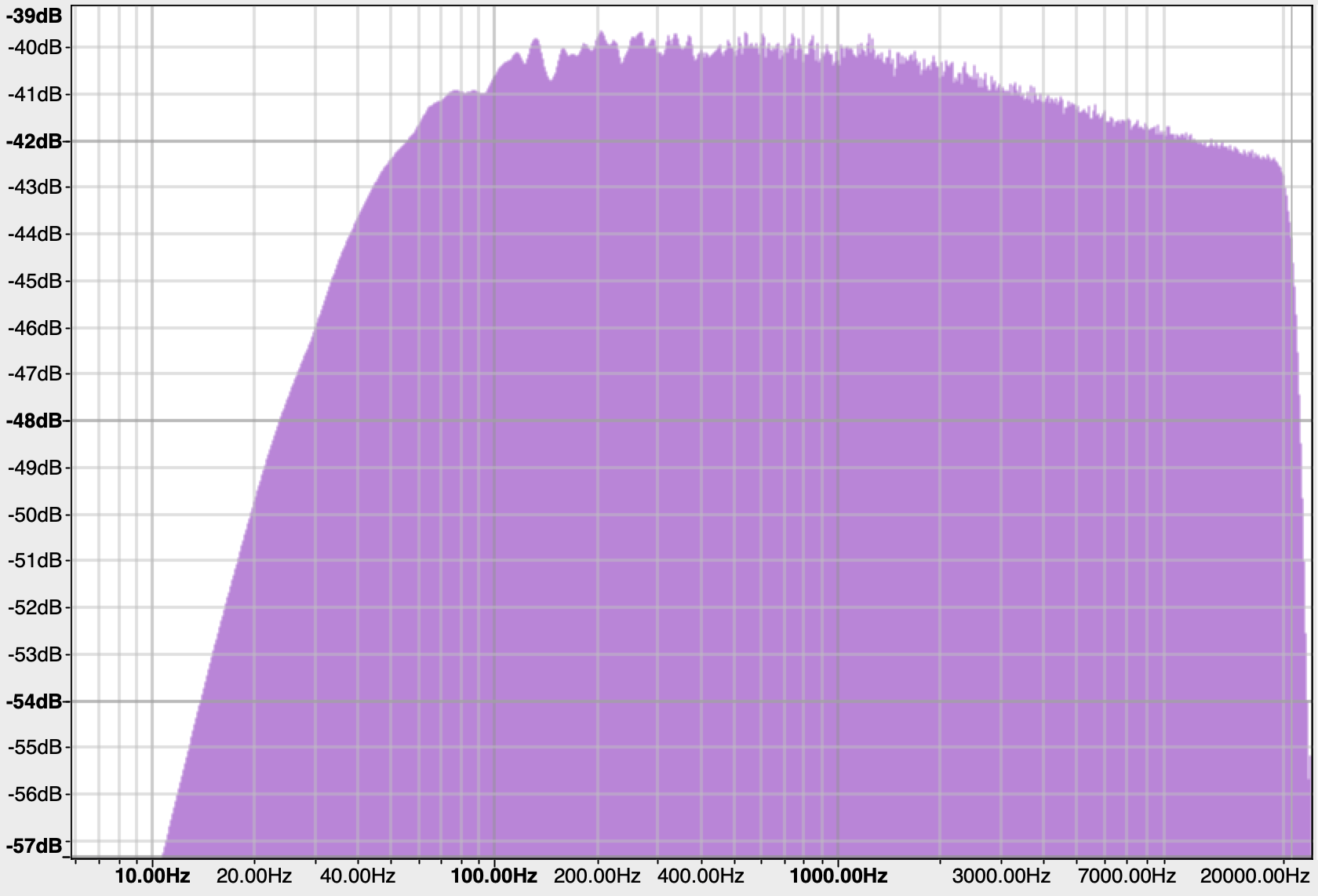
The White noise output is flat to within 2 or 3dB over the audio range.

The Pink Noise follows the theoretical -3dB/octave slope over the audio range, and beyond, although we can’t see that here. The sharp drop-off above 20KHz and below 50Hz is due to the limitations of my digital recording set-up. The unit has steep anti-aliasing filters at 20KHz.
So how did this come about?
Adding pink noise generation to my chip was suggested by Richie Burnett, who I know from the Synth-DIY list. He suggested the “Voss-McCartney algorithm” as the best method of doing it. I hadn’t heard of this, so I went off to research it.
The Voss-McCartney Pink Noise Algorithm
The algorithm was first proposed in a 1978 paper by Voss and Clarke, and then became well known after being featured in a Martin Gardner column in Scientific American. The basic idea of the algorithm is to generate a pink noise sample by adding together lots of white noise generators that have been sampled at different rates. In the Voss algorithm, each generator is sampled at half the rate of the last one.
The topic and the algorithm came up in a discussion on the music-dsp mailing list in August and September 1999, and several further refinements were added. The major one was James McCartney pointing out that by shifting the update times of the different generators, only one would need to be updated each sample. This evens out the computational load of the algorithm and makes it much more practical. It does throw up one interesting question though, which is how we efficiently generate the tree-like structure that is required to determine which output should be updated.
A further refinement is to add a white noise source at the full sample rate. This helps “fill in” some of the nulls in the frequency response and smooths the performance somewhat.
How good is the Voss-McCartney algorithm?
A theoretical pink noise source produces noise down to 0Hz and up to infinity (although exponentially decreasing), so the first thing to say is that any *actual* noise source, white or pink, is designed for a given frequency range and to given degree of accuracy. For musical purposes, we’re looking at the audio range from 20Hz to 20KHz, and while we might want our white noise to be reasonably flat across that range and our pink noise to be reasonably even, we’re not going to worry about a few decibels here or there. This is not a piece of test equipment, and having a super-high-accuracy pink noise source won’t make your synth sound better. It’s more important that it sounds good and is useful for music.
With that said, let’s have a look at the response of the Voss-McCartney algorithm. Allen Herriman points out that one way to think about the algorithm is that it is a white noise source being sampled by a sample-and-hold.
This gives us a way of getting a grip on the frequency response. The sampling-and-holding process gives a frequency response of (sin(x) / x). We can plot this response for the different octaves and see how they add together. Here’s an example at a sample rate X:

Halving the sample rate squashes the spectrum to the left. This is significant because this squashing means more of the lumpy part on the right moves down into the region we’re interested in. Here’s what happens when we reduce the sample rate to X/2:

As we move down the octaves, more of the noise power gets pushed lower and lower, but more little lumps get introduced in the higher frequencies. This is the next octave down, with a sample rate of X/4:

If we keep adding lower and lower octaves, we can build up our pink noise response. On this graph, the theoretical slope is shown in magenta, and the final response is shown in blue. This theoretical result matches our actual response shown at the top of the page rather well. The magenta vertical line is at 25KHz, the highest audio frequency we care about. The final result is basically within +/-2dB of the theoretical slope, apart from at the very highest audio frequencies, where it starts to droop a little bit by 4db or so.
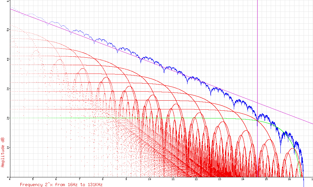
It’s clear that the response is still a bit “lumpy”. Unfortunately, adding more generators doesn’t help. The lumps happen because the generator’s sample rates are all related in neat octaves. We can avoid the lumps by setting up the generators at non-multiple sample rates. This works, but generating several prime-number sample rates is a computational nightmare. Alternatively, we could randomise the output sample rates a bit, or a lot, even. This is the basis of Larry Trammell’s Stochastic Voss-McCartney Algorithm, which I’m not going to describe here because it’s beyond what we can realistically manage, or what we realistically need. There’s a link for it in the references at the bottom, and it’s definitely worth a read.
Are there alternative approaches?
The other obvious way to generate pink noise is to copy the analog approach of filtering white noise, but to do it digitally. This can provide a very accurate pink noise response if you have a filter with enough poles and zeros. Unfortunately, there is no way a PIC is going to be able to calculate such a filter at the kind of rates necessary. This is a non-starter.
There’s another method presented by Stefan Stenzel of Waldorf Music, but again, although his method is clever and efficient on an ASIC, it’s not suitable for a low-end processor.
Can Voss-McCartney be done on a PIC?
Ok, so we’ve established that the algorithm produces decent, if not perfect, quality pink noise. The next question is “is it practical on a PIC processor?” This is not simple to work out ahead of time, but we can do some back-of-the-envelope calculations to see if it’s “easy”, “close”, or “no chance”. Let’s assume we want a 100KHz output sample rate. This gives us theoretical bandwidth out to 50KHz, which should be more than enough to keep any weirdness at the high end away from the part we care about. We’re going to need a fast processor, so I started by looking at the 16F18313 that I used for the StompLFO project since it can run with a 32MHz internal clock, giving a 8MHz instruction rate. This enables us to work out how many instructions we have available per sample: 8MHz/100KHz = 80 instructions. Ouch. That’s a few, but it’s not many, and this algorithm might eat them up pretty fast. So this definitely gets filed under “Going to be close”!
Breaking the algorithm down a bit, there are various stages:
-
- Update the LFSRs
- Update one of the outputs
- Add a constant white noise source
- Add up the various outputs
- Send the result to the outside world
Simple, right?! Let’s see.
Updating the LFSRs
Firstly, it’s worth pointing out that we only need two LFSRs, despite having a lot of generators. That’s because by using the McCartney trick of shifting the updates, we only ever update one octave generator and one white noise sample each time.
The code for our two LFSRs looks like this:
;	Update the two LFSRs
;----------------------------------------------------

	; 31-bit LFSR with taps at 31 and 28
	;----------------------------------------------------
	; This is our white noise source, and is also the fixed white
	; noise element of the pink noise source.
	swapf	LFSR1_4, W	; Get tap 28
	movwf	TEMP
	rlf		LFSR1_4, W	; Get tap 31
	xorwf	TEMP, F
	; Shift the XORd bit into carry
	rlf		TEMP, F
	; Shift the register
	rlf		LFSR1_1, F
	rlf		LFSR1_2, F
	rlf		LFSR1_3, F
	rlf		LFSR1_4, F

	; 21-bit LFSR with taps at 21 and 19
	;----------------------------------------------------
	; This is used for the lower octaves
	rrf		LFSR2_3, W	; Get tap 19
	movwf	TEMP
	rrf		TEMP, F
	swapf	LFSR2_3, W	; Get tap 21
	xorwf	TEMP, F
	; Shift the XORd bit into carry
	rrf		TEMP, F
	; Shift the register
	rlf		LFSR2_1, F
	rlf		LFSR2_2, F
	rlf		LFSR2_3, F
Updating one of the outputs
The next problem is how to work out which one of the shifted outputs we should update. How do we generate that interesting tree-like structure?
Simple! We don’t! Whenever I see anything vaguely complicated, I go running for a look-up table, and this is no different.
;	Update one of the LFSRs
;----------------------------------------------------

; First, we need to know which one we're updating
SelectOutput:
	; Update the tree structure counter
	movlw	D'1'
	addwf	COUNT_LO, f
	movlw	D'0'
	addwfc	COUNT_HI, f

	; Find out which output we need to update
	movf	COUNT_LO, w
	call	TreeTable

	; Update the correct output
    brw
    goto	Octave0				; Updated every 2nd sample
    goto	Octave1				; Updated every 4th sample
    goto	Octave2				; Updated every 8th sample
    goto	Octave3				; etc..
    goto	Octave4
    goto	Octave5
    goto	Octave6
    goto	Octave7
    goto	Octaves8to13		; These only come around every 256th sample

Octave0:
	; We assume the bit is cleared, and then set it if neccessary
	bcf		OUTPUT_LO, 0
	btfsc	LFSR2_2, 0			; Doesn't really matter which LFSR bit we use
	bsf		OUTPUT_LO, 0
	; The other outputs are done in exactly the same way
	goto	Octaves8to13Compensation

Octave1:
	bcf		OUTPUT_LO, 1
	btfsc	LFSR2_2, 0
	bsf		OUTPUT_LO, 1
	goto	Octaves8to13Compensation
You can guess what Octave2 to Octave7 look like. If you can’t, check the entire code. The Octaves8to13 routine repeats what’s above, but only gets called once every 256 samples, so it provides all the lower octaves. The fact that there’s a variable length here (Octaves 0 to 7 only do one set of branching, where Octaves 8 to 13 do two) explains the need for the Octaves8to13Compensation routine, which is just a bunch of NOP (“No Operation”) instructions to keep the two paths the same length in terms of instruction cycles.
Add the constant white noise
This is simple. We just take the output from our white noise LFSR and stick it into a spare bit in the output bytes.
;	Add white noise every sample to fill in the nulls
;----------------------------------------------------
AddWhiteNoise:
	; This uses the other LFSR, but is otherwise identical
	bcf		OUTPUT_HI, 6
	btfsc	LFSR1_4, 0
	bsf		OUTPUT_HI, 6
Add up the various outputs
Ok, so we’ve got two bytes, OUTPUT_LO and OUTPUT_HI, containing the values of our random generators. We need to add up the output of all the generators and send it to the DAC. This is a basic “bit counting” task. I’ve organised things so that there are a maximum of 15 bits (14 octave generators and the constant white noise generator).
Again, the quickest way is a look-up table. We can use each byte as the index into a table which tells us how many bits are set in that number. We do this twice for the OUTPUT_LO and the OUTPUT_HI and add them together.
;	Add up how many of the outputs are set
;----------------------------------------------------
; We do this with an 8-bit look-up to save actual adding
AddUpBits:
	; Add up the number of bits from Octaves 0-7
	movf	OUTPUT_LO, w
	call	NumOfBitsSet
	movwf	TEMP				; Store it in TEMP
	; Add up the number of bits from Octaves 8-15
	movf	OUTPUT_HI, w
	call	NumOfBitsSet
	addwf	TEMP, f				; Add the number in TEMP to get the total
	; We have the total number of bits in TEMP
Send the result to the outside world
This is simple too. We just copy the TEMP value we just generated into the DAC output register. It’s a 5-bit DAC, so we shift it over one bit first to use the most significant bits not the least significant.
OutputToDAC:
	lslf	TEMP, w				; Shift up to 0-30 range
	movwf	DACCON1
The entire thing runs in very close to the 80 instructions we were aiming at, so we basically get our 100KHz sample rate. We can output the white noise source to a pin too, and then we have a chip which provides both white and pink noise outputs on a single 8-pin chip. Just add 5V. Actually, sometimes it’s not quite that simple. The pink noise DAC output can’t source much current, so if it’s not feeding a high impedance, it’ll need buffering. This is because the resistor string DAC used has a high output impedance (and one that depends on the value set, too).
Fantastic! I want white and pink noise!
Well, there’s the usual options for Druid chips – program your own, or we’ve got some in the shop.
- PIC 16F18313 assembly code NOISE2.ASM
- Compiled version of the above, ready to program NOISE2.HEX
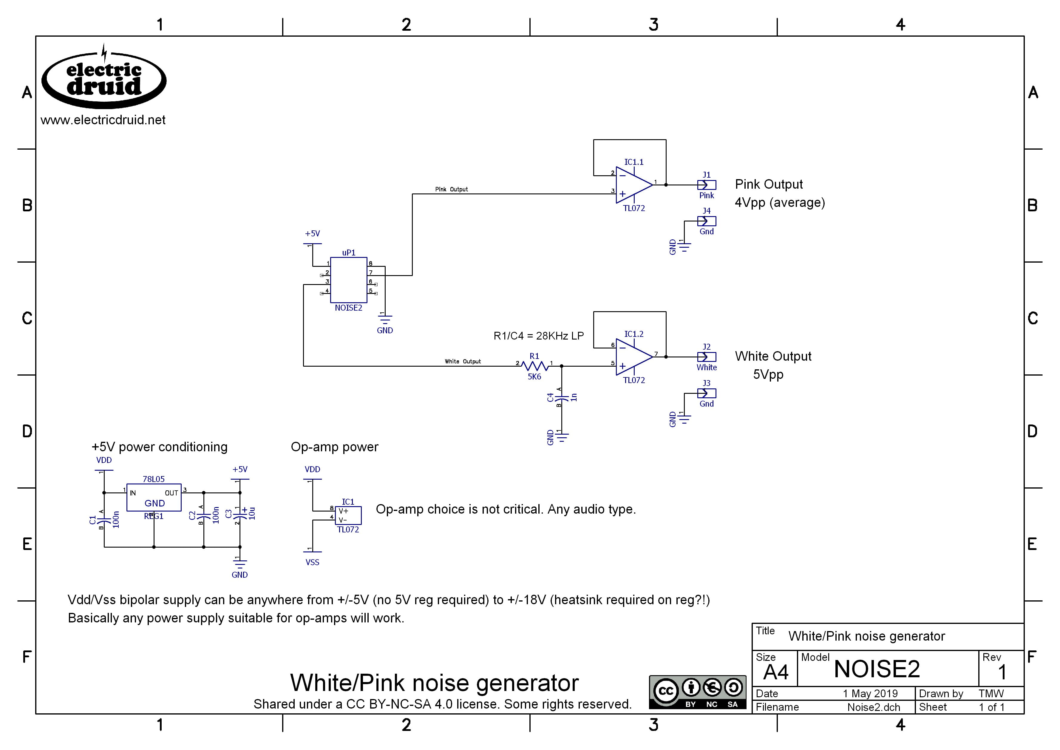
- NOISE2 datasheet, including schematic diagram
The schematic diagram is very simple. I added simple RC roll-off at 25KHz just to turn the digital pulse white noise into something more analog-looking. It sounds just the same though, but it makes a difference if you’re modulating things with it. Both outputs have been given op-amp buffers to protect them. As mentioned above, the Pink output cannot drive significant loads, so this buffer is a good idea. For the White output, it prevents subsequent circuits affecting the filter.
Credits and Feedback
Many thanks to Richie Burnett for bringing this algorithm to my attention in the first place, and for all the help via email, both on this project and others. It’s much appreciated, Richie.
Thanks also to Robin Whittle for his excellent page about the topic, which taught me a lot, and the other people mentioned in the references below, all of which I’ve found very useful and interesting.
Any mistakes spotted, feedback, or ideas for further development are always appreciated. Please get in touch.
References:
The original Voss and Clarke paper:
Voss, R. F., & Clarke, J. (1978). “1/f noise in music: Music from 1/f noise”. Journal of the Acoustical Society of America 63: 258–263.
Martin Gardner’s article:
Robin Whittle’s discussion of the history of the algorithm on the music-dsp list:
http://www.firstpr.com.au/dsp/pink-noise/
Larry Trammell’s description of the development of his “Stochastic Voss-McCartney Algorithm”:
https://www.ridgerat-tech.us/pink/pinkalg.htm
Stefan Stenzel’s “new shade of pink” algorithm on Github. You can also read his paper.
Dear Sir´s
Please be so kind an inform us by @-mail when You NOISE2 programmed generator chip is available in Your shop.
No problem, we’ll let you know. It should be available shortly.
I’d be interested too!
..as well as One-Shot Event/LFO generator 🙂
Hi Tom
thx, interesting work you did for the pink noise generator.
I’m using your Noise Pics in various of my Synth Projects.
One thing that just came to my mind….
Do you think it would be possible to create “blue Noise” by using a sort of “reversed” Voss/Clarke algorithm?
Maybe it would even be possible to do coloured Noise?
and then using an analogue Input to change noise colour :-0
On the other Hand all that can easily be done with analogue filtering (my way of doing it)
best regards, Thomas
Interesting ideas! I’m not sure, I’ll have to think about it. Thanks for the thought.
Maybe it is not hearable, but what noise cycle repeat time?
Roughly six hours. I think you’ll have forgotten what the beginning sounded like by then!
Hi. I programmed the chip (PIC, NOISE2.HEX)
But the sound of pinknoise is different from your example (white is great). In the noise random
HF clicks are heard, sound is irregular.
That doesn’t sound right! Have you got a sound sample?
Sample of my pinknoise
https://mega.nz/file/wQEmybLT#5zrKK3re90Y9e66ao_QBKEK1tgD6pK0jRPjfbORfN0E
Humm, that does sound glitchy. Could the chip be crashing and restarting for some reason? What are you using for a power supply? What have you got on the output?
I came across a similar issue on another chip, and eventually we traced it to the circuit being run from USB power. There was enough noise on the USB’s “5V” supply that the chip kept crashing and resetting.
I tried USB and battery power (3 x AA battery), but the result was the same. On the output i used a buffer amplifier and direct connect to sound interface (mic balanced input Audient id14)
I purchased the noise2 chip from you back in February,and I’m having an issue with it.
I used the circuit you supplied , and here is the issue. When using the 78L05 circuit with C3 (10uf) the voltage is a stable 5v but the outputs are very low from the chip and the chip draws about 64ma, in scoping the output of the white noise I see 59mv’s of signal. The chip also runs very warm, I am using a very regulated and filtered bench power supply for 12v into the 78L05. Which does not give me the expected output of 5v pp when putting this into the TL072. If I remove the C3 cap the power of course drops to about 2.6volts the current drops to 37ma and the output of the pic chip is at 504-506mv pp. is this normal or is this chip defective. In downloading the data sheet and looking at the current consumption on it , it appears to be drawing too much current , any suggestions.
This sounds like the chip has got damaged somehow. Static, maybe? That’s definitely not normal. Although your comment about the 78L05 “not giving the expected 5V” is suspicious – does the 5V power not work correctly all the time?
How to compile the assembly code “NOISE2.ASM”.MPLAB IDE doesn’t support PIC16F18313,and the new MPLAB X IDE has no MPASM.
Hi Eric,
Yes, Microchip saw fit to drop MPASM support after V4.1 or so. I’m still using V4.05 to maintain my legacy code. The new MPLAB X versions *must* support the 16F18313, since the old ones did! Or have Microchip turned *completely* stupid?!?
It’s annoying, and I don’t what I shall do in the future. The new assembler is a mess compared to the old one.
Tom
Hi Tom,thanks for your explanatio.