
How do you synchronise your modular synth with MIDI equipment? MIDI provides the MIDI clock message, but you need something to convert this to a format an analog modular synth can understand. Most MIDI-to-CV convertors will do the job, but that can be expensive. Here’s a cheap way to do it.
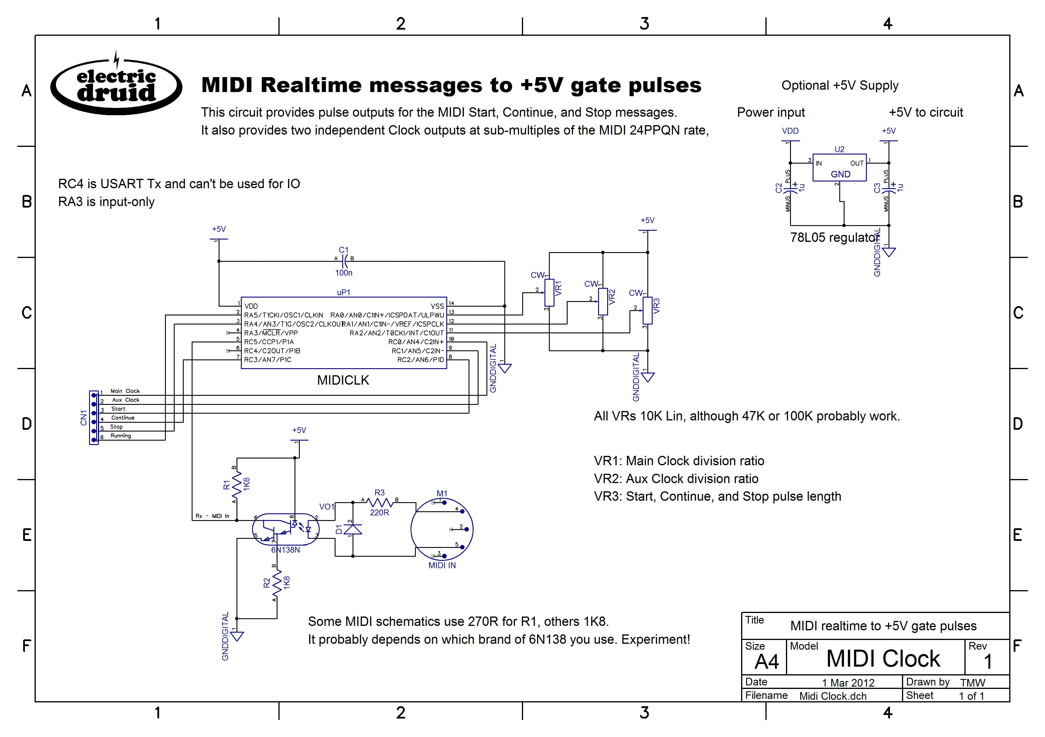
The Druid MIDICLK chip converts MIDI clock signals into 0-5V analog pulses. It provides two separate analog clock outputs, which can be set at various division ratios of the MIDI clock, which allows crazy polyrhythmic mayhem if you’ve got two independent sequencers. It also produces short 0-5V pulses for the MIDI Start, Stop, and Continue messages, as well as providing a ‘Running’ output which is high whilst the MIDI clock is running. These signals can be used to control your analog circuits.
Below is a example circuit which shows the various features of the code. It uses potentiometers for all the options, but for specific applications, these could be presets or particular voltages. For example, it’s unlikely you’d really need VR3 for control over the Start, Stop, and Continue pulse length. You’d pick a couple of resistor values and set up a divider that gives a reasonable pulse length for your circuit, or tie the pin to ground with 10K if you’re not using those outputs.
Great, but what could I actually use that for?
The circuit above will replace the typical LFO clock in most analog sequencer designs and allow you to synchronise your analog sequencer with your MIDI equipment.
It can also be used to synchronise the sequencers in monosynths like the SH101 or the Sequential Pro-One. Using an external clock with these synths frees up the LFO when the sequencer is running, which is a big step forward!
It’s a simple circuit, and it’s only designed to do one thing.
More details
If you’d like to build one, or like to know how I built mine, perhaps you’d like to look at:
- MIDICLK PIC 16F688 ASM code
- Assembled HEX code from above file
- MIDICLK datasheet (includes example circuit diagram, chip pinout, and details of division ratios)
We do have a few programmed MIDICLK chips in the shop, so if you don’t want to mess around with a programmer, you can grab one from there.
hi tom
amazing stuff you have here 🙂
i used the noise source to modify the little korg monotron with added noise. with the pic (smd version) it was possible to include this in the korg monotron itself.
i was just looking at your midi to din clock project, but the asm source code is for the vcdo and not the midi clock source……
best regards
tom explosion
Fixed, sorry! I’d have sworn I’d changed that link…
Hey Tom!
What’s the best way to collaborate it with the LoopEnv and the tap LFO chips?
For the TAPLFO, it’s simple. You’d feed the output from the MIDICLK chip to the Sync input of the TAPLFO schematic (Far right, R24 to base of TR1 – see this schematic). You can’t feed it in directly because the Tap Tempo input is inverted logic.
For the LoopEnv, I don’t know. You could use the MIDICLK clock signal as a series of gate pulses for the LoopEnv. That’d work, but it’s not very exciting. There isn’t an obvious way to synchronise the LoopEnv LFO rate with MIDI, since the speed the LoopEnv loops at depends on the settings of its Attack, Decay, and Release CVs. Hope this helps!
I regret trading in my Roland Juno-60 20 yrs ago because of its arpeggiator but even more so because I didnt realize at the time, it was the only polyphonic synthesizer I know of that had an external trigger / clock input for running in time to the clock pulses of an external sequencer or drum trigger source, that could clock the arpeggiator or be used to retrigger a chord, until the next chord was played which allowed hands free playing to do other things. back in the 80s.
So now my question is that I would like to somehow filter out of the midi stream the actual key triggers from playing the keys of a keyboard on its way to an external midi sound module, and filter in an external trigger source from an external clock or pulses from a sequencer or drum machine like the Roland TR 808 / 707. How would one go about doing that ? instead of buying another used Juno-60 at above the list price I paid for one 30 yrs ago !?!?!!?!
It can be done. A “hardware MIDI arpeggiator” is what you’re looking for. They’re a pretty rare beast, since everything has gone VST/AU/software these days. You’d probably have to build one, in which case, Olivier Gillet’s work is always excellent:
http://mutable-instruments.net/midipal
There’s also a closely related project:
http://midisizer.com/midigal/
About the only other one I could find was this, available as a kit or constructed:
https://www.tindie.com/products/hotchk155/arpie-midi-arpeggiator-kit-1/
Hope this helps!
Which channel of the 16 channels work?
you can add the ability to select the channel?
The MIDI Clock, Start, Stop, and Continue messages are all part of the “System Realtime” part of the specification. There’s also “Active Sense”, but it’s mostly ignored these days. These messages are not “Channel voice messages”, so they don’t have a MIDI channel. They’re sent to everything, and whether you do anything with them is up to the receiving device.
I am looking for a circuit that face the other direction.
A pulse CV Trigger to Midi out, with the ability to select the MIDI channel
You’d like to input an analog pulse, and output a MIDI Clock? No MIDI channel selection is necessary, as I said above. This isn’t difficult to do, but the problem is that most analog equipment works using one pulse to move to the next step of a sequence, often 16th notes. This is four clocks per 1/4 note. MIDI uses 24 clocks per 1/4 note (Helpfully, some Roland x0x gear uses this same rate, but it’s about all that does). This means you have to use an analog clock that is much faster than usual, and you have to put a divider between it and your analog sequencer or other gear.
I have wondered about working on a Analog/MIDI clock chip that could output signals useful to both domains though. It’s on the list for one day…
I would love to see this kind of thing elaborated upon. I’m using your midi to pulse converter to sync your TAPLFO chip to allow for CV 5V output but I would also love to have a Midi out that takes the pulse from the TAPLFO and converts it back into a midi clock output.
Thanks Colin!
I may well do some more work with this type of thing in the future. I’ve got one or two uses for it myself! Going from TAPLFO pulses to MIDI clock is more difficult but not impossible. It’d involve synchronising a higher speed clock to the incoming pulses, sort of like a phase-locked loop or similar.
Another possibility I’ve wondered about is to add a MIDI input to a new version of the TAPLFO, so it can directly provide waveforms at multiples of the MIDI clock rate (e.g. add the ability to sync to MIDI Clock as well as incoming pulses).
Tom
Have a look at this MIDI clock – it offers analog out also: http://www.erikoostveen.co.uk/#anchor2
Very nice! Thanks for sharing that!
Tom
hi lovely project. I was hoping to use something like this to do DINSYNC in my setup. Would it be a matter of connection start & stop together through diodes to pin 1 of a DIN plug. Clock going to pin 3. Many thanks Alan
Hi Alan, I think that what you suggest with Start and Stop would work. Tie them together with a diode-Or, and probably add a 10K pull-down to ground for when neither signal is high. The problem is that the code as written toggles the outputs when a MIDI clock pulse arrives, so the fastest clock output is 12PPQN, whereas DIN Sync needs 24PPQN. It can probably be tweaked to output a pulse every time a MIDI clock arrives, but it won’t do it “off the shelf”. Sorry.
Tom
dear Tom!
Thanks for sharing the schema and the code!
Works great for me!
I’m planning to replace the pots with rotaries because sometimes its a bit hard to find the right position.
Can you explain the division?
Basically the code keeps a decrementing counter running, and every time a MIDI clock (24PPQN) comes in, the count is decreased by one. When it reaches zero, the output toggles. So a counter reset value of 1 will give 12PPQN output, a reset value of 2 will give 6PPQN, etc. The available values are:
HTH,
Tom
Thank you Tom! 🙂
Hi Tom, thanks for sharing the code and the project. I have noticed that when turning the clock ratio pot while the clock is running it loses the first beat. Have then to stop the clock and start again. I wonder if this is easy to change. Many thanks. Goncalo
p.s. by the way, it seems that by stoping the midi clock, the pic is not reseting properly. When the clock starts again the pic starts where it stoped instead from 1 beat. Thanks again
It’s going to be pretty difficult to change. The reason being that the time when the change is made might not make sense when switching to a different ratio. How do you switch from triplets to sixteenths without losing something, unless you happen to have just finished the third triplet? It’d be possible to only switch at times that match, but then that will introduce a variable amount of delay (since the chip will likely have to wait until the next safe point to switch comes along), so it’s not ideal either.
Thanks
Hi Tom,
thanks for designing and sharing this project. It’s not clear to me if there is already a choice for 1/32 (8 clocks per QN ), if not how could one implement said division in the ASM? I know my assembly skills are dull 😐
thanks in advance
Massimo
No, there’s no option for 8 clocks per quarter note. Because of the way I did the code (the simple way!) it’s not possible. Sorry!
Hi Tom,
Just found your awesome sites and project, thanks for sharing.
I have the Pic16f684 ic’s laying aroundand the Pic16f688 is hard to find in my country.
And I read in the datasheet there is only different in RAM and FLASH memory size if I’m not correct.
Before I build it and wont ruin the Ic’s, just one question,
Can I swap the pic16f688 to 16f684 ?
If so, should I change the Asm file or leave at it is?
Thanks
Tobie
The problem with the 16F684 is that it has no UART module (“EUSART” in microchip-speak). That’s required for the MIDI input. The 16F688 has this EUSART module, so it’s a good chip for little MIDI projects.
Also be aware that since I wrote this code, Microchip have dropped support for PICASM in MPLAB X. I’m currently still using V4.05 to get around this, one of the last versions that included it. There’s a new assembler in the more recent versions, but it’s not really compatible.
Oh ok, good to know. I will try to find the chip then. Thank you for the replied.
Hi Tom,
I built the example circuit on stripboard (using a 10K trimmer for VR3 and 270R for R1,though I think 1K8 would work too). I tested the circuit using a LED to visualise the clock pulses (midi coming from a Korg SQ1) and noticed that they very faintly light up when VR3 is turned ccw (starting from a certain setting). Could it be that a small voltage offset is introduced by setting VR3 to a certain point? I haven’t tried out the circuit with a module yet (front panel still needs to be build) but think it will work without problems, just wondering what causes the offset or if it’s by design.
Wim
VR3 is the output pulse length, so I’d expect it to affect the brightness of the LEDs. CCW will be less, CW will be more. There’s no offset going on – you’re seeing very brief pulses as a low LED level because of persistence of vision.
VR3 shouldn’t affect the MIDI Clock outputs, since these are square waves, not a monostable pulse. The range of pulse lengths is from 256us to 65.5ms.
If you’re having trouble with it, get in touch and we’ll discuss it.