
Flangers are generally regarded as one of the most complicated pedals to build. A typical design has tons of chips and lots of circuit elements. Flangelicious isn’t like that.

By using a microprocessor to generate an LFO-modulated clock signal directly, we can get rid of a lot of the non-signal path stuff and add features whilst we’re about it. This gives us a much cleaner, simpler design for a flanger with a genuine fully-analog signal path. In fact, it can all be done with just four 8-pin ICs.
Flangelicious sound examples
To give you a flavour of the sound of the Flangelicious, here’s some sound samples recorded through the unit pictured above (my personal “blue meanie”). These are completely dry guitar samples played through the pedal and recorded into the computer – no amp, no amp modelling, no other effects, nothing. This pedal is the classic four-knob flanger version, equipped with an 1024-stage MN3207.
Two versions of Flangelicious
The Flangelicious comes in two versions: a classic four-knob flanger, and a more experimental multi-waveform flanger. They’re identical apart from the FLANGE chip you use, and both versions can be built with the same PCB with no component changes, and both versions can use either 1024-stage or 256-stage BBDs for different tonalities. You can even build one PCB, and swap FLANGE chips and BBDs back and forth. Let’s have a look at the two versions:
Classic four-knob flanger (4KNOBFLANGE chip)
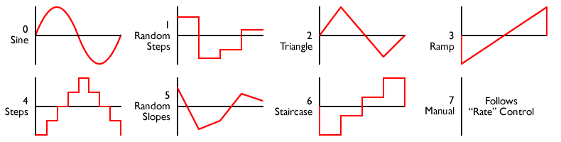
The Druid 4KNOBFLANGE chip offers control for Manual flanger frequency, Depth, Rate, and Resonance (Feedback). The LFO uses a specially shaped waveform which avoids the abrupt changes of a triangle LFO, but avoids the apparently-doing-nothing periods at the peaks of a sine LFO. Manual, Depth, and Rate are all variable using 0-5V control voltages. The chip outputs a biphase clock from 25KHz to 500KHz that can drive MN-series delay lines directly.
Experimental Multi-waveform flanger (MULTIFLANGE chip)
The Druid MULTIFLANGE chip includes an LFO with eight waveforms, including a “manual” mode for fixed flanger (“matrix”) filtering effects. Rate, Waveform, and LFO Depth are all variable using 0-5V control voltages. The chip outputs a biphase clock from 25KHz to 500KHz that can drive MN-series delay lines directly.
So why build a Flangelicious rather than something else?
Comparing the Flangelicious schematic with another flanger of your choice will show you the benefit to be gained by rolling up the LFO and voltage-controlled clock into a single chip. In some designs, this part is a third to half the circuit.
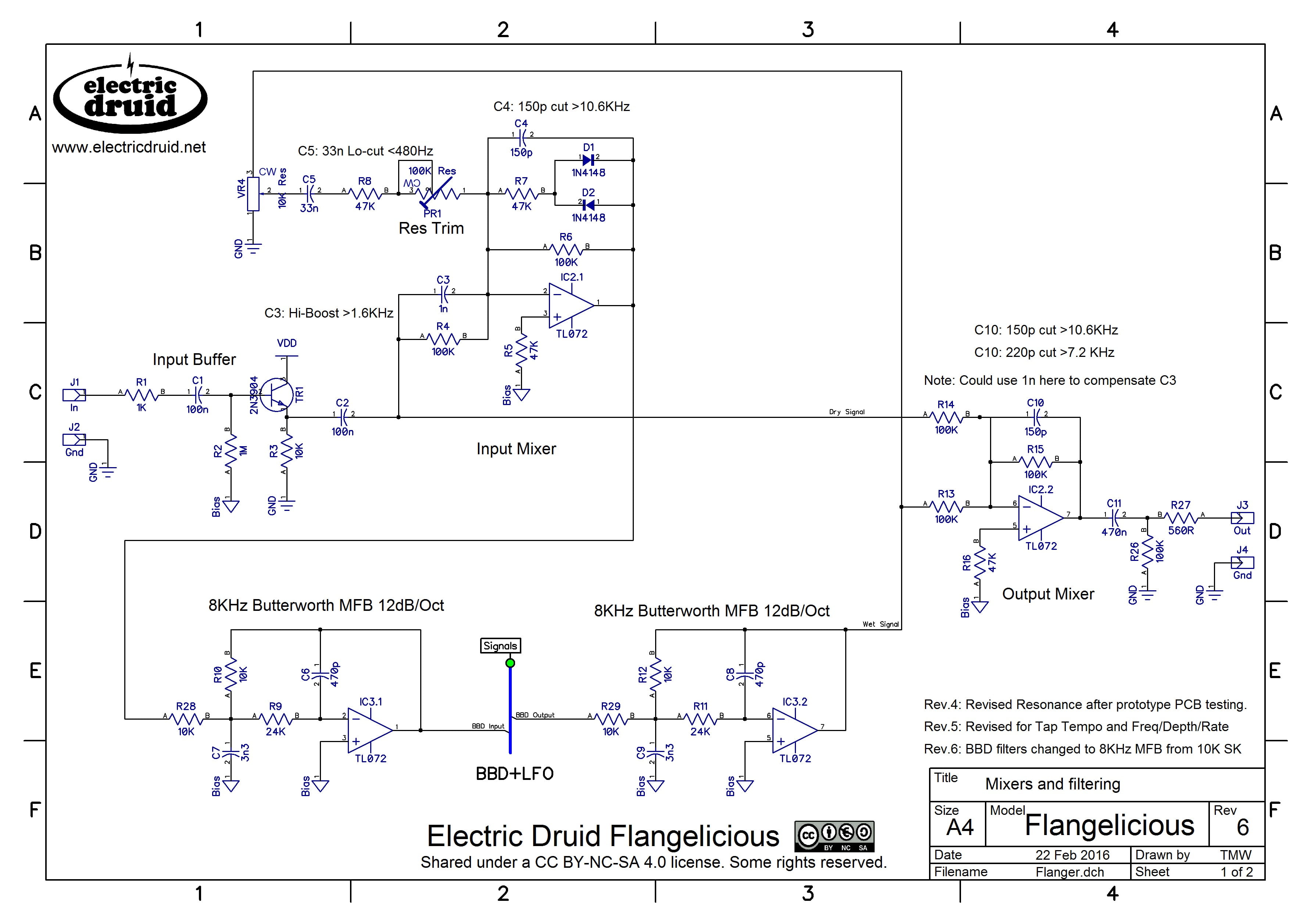
What doesn’t change is the analog signal path – input mixer with feedback for that resonant flanger sound, pre-BBD filter, BBD, post-BBD filter, and output mixer to mix the wet and dry signals to produce the flanging. Luckily for us, this can be done with four op-amps and one BBD chip – just three more 8-pin chips.
In the Flangelicious design, the BBD filtering is deliberately kept fairly light, and set at a frequency to give as much top-end as possible. Flangers love sounds with lots of rich harmonics, so it seems a shame to remove them all. For the same reason, there are tone-shaping components scattered throughout the circuit to boost harmonics but roll-off noise. These are all clearly marked and labelled, and are ideal places to start tweaking to customise the circuit for your perfect tone.

The Flangelicious PCB can accept either MN3209 256-stage delay lines or MN3207 1024-stage delay lines (or the modern equivalents like the BL3207). The different delay lengths provide different tonalities, but both provide a solid flanging sound.
Problems and Possibilities – some personal notes
This project has been one of the most difficult to finish that I’ve worked on. I’ve been playing with it since at least summer 2012, so it’s been nearly four years on the bench. This one has really spent its time in development hell before it escaped to see the light of day. One problem is that the 8-pin chip only offers three analog-to-digital channels (CV inputs). This means that if you want to add a “Waveform” control, you have to drop the usual flanger “Manual” control. In the end, I decided that both options are worthwhile, so that’s what I’m offering. I’d be interested to hear what people think of this decision.
On the positive side, I’m pleased with the code. It’s pretty sophisticated stuff for a 8-pin, 8-bit chip, and it makes full use of the both the features of the newer “Enhanced” 12F1xxx processor and also of all the coding tricks I’ve learned over the last few years. The interrupt routine is kept short, just reading values from ping-pong buffers, and the real work is done using DSP-style block processing as required in the main loop. Without these techniques, there’s no way this chip could pull this off. As it is, every single byte of the extremely limited RAM is used, and the Program Memory is over 95% full too, so even like this, it’s a tight fit.
PCBs and chips for this project

PCBs and programmed chips for this project are available in the shop. You need the Flangelicious PCB + chipset, which includes your choice of the two versions and BBD. You might also need a set of pots for the project.
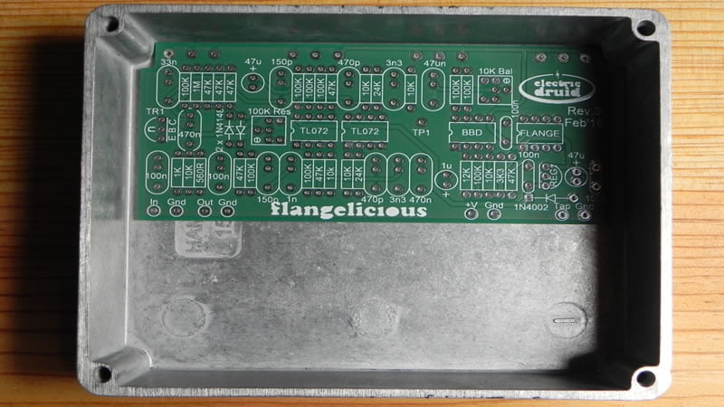
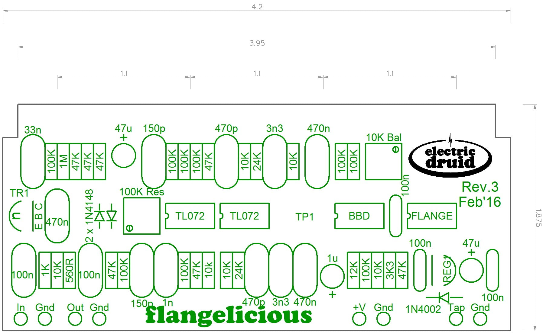
The photo above is the Rev.3 PCB, which allows for caps with a lead spacing of either 5mm/0.2″ or 7.5mm/0.3″ to be used to make life easier for DIY. For the build above I used my favourite Wima box film caps, which have a 5mm spacing. Similarly, the PCB layout for the two trimmers can accept the pinouts of several different types of trimmer. The latest PCB is the Rev.4, which is basically identical, but adds a cutout in the top edge to make fitting a DC socket slightly easier.
The PCB measures 106x48mm. It is designed to fit into a Hammond 1590BB enclosure in landscape format. The PCB-mounted pots make the build easier.
Ok, so what do I need to build one?

Pop over to the shop and grab the Flangelicious PCB + chipset, which includes your choice of the two versions and BBD. You might also need a set of pots for the project.
Alternatively, you can get a complete parts kit from Germany, from either Das Musikding (Four Knob Flanger / MultiFlange), or UKElectronic (Four Knob Flanger / MultiFlange).
The only document which you’ll really need is the Flangelicious construction guide.
Project files
Here are the full details if you want to tweak the code, do your own PCB, or otherwise experiment with it.
Four-knob classic flanger
- 4KNOBFLANGE.ASM code
- Assembled 4KNOBFLANGE.HEX code from the above to program into a 12F1501 chip
- Datasheet for the 4KNOBFLANGE chip
Experimental Multi-waveform flanger
- MULTIFLANGE.ASM code
- Assembled MULTIFLANGE.HEX code from the above to program into a 12F1501 chip
- Datasheet for the MULTIFLANGE chip
Files common to both versions
- Rev.6 Schematic (Page 1)
- Rev.6 Schematic (Page 2)
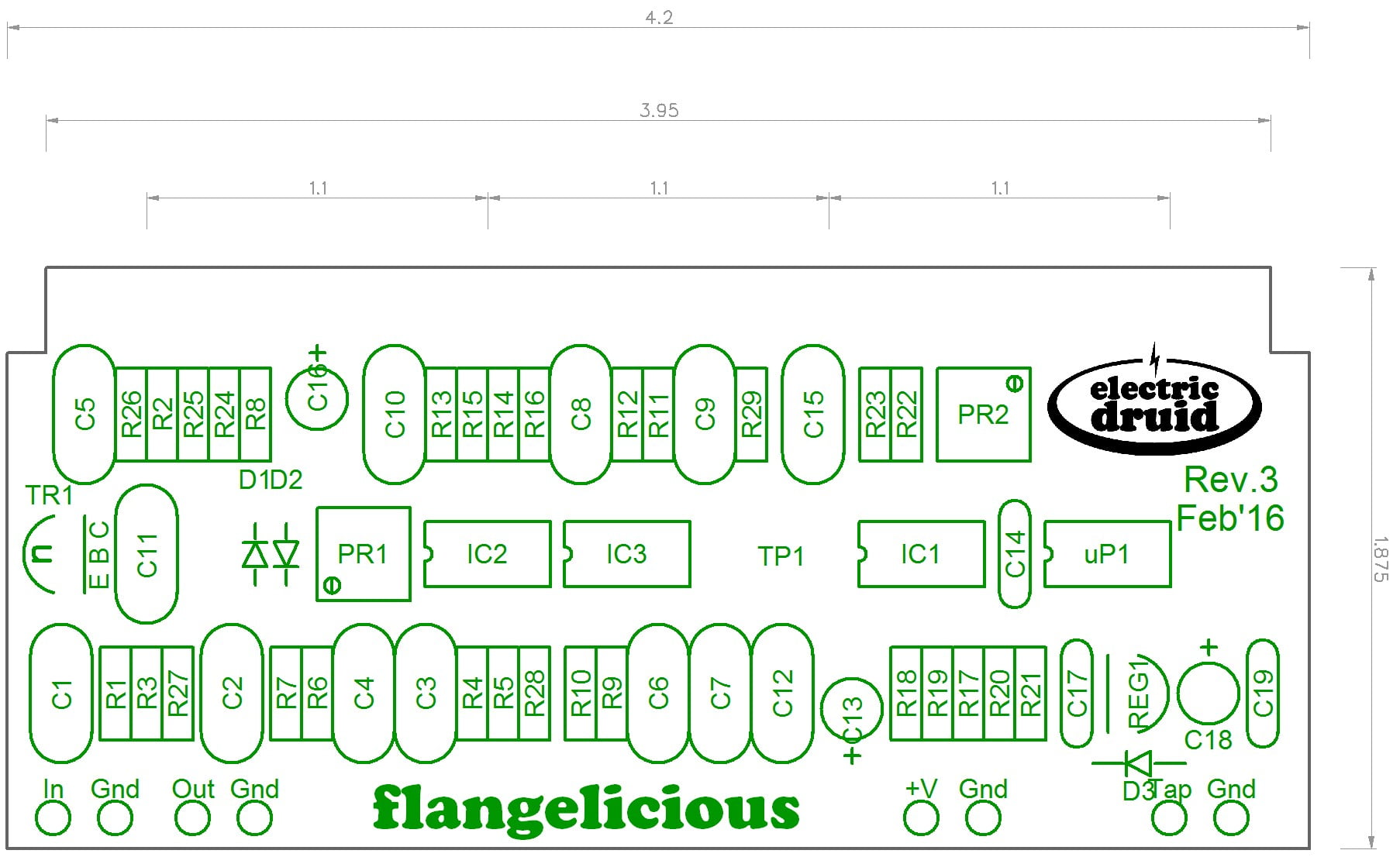
- Rev.3 PCB Reference Designators
- Rev.3 PCB Component Values
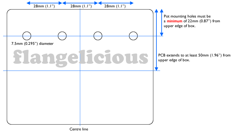
- Enclosure drilling guide
- Flangelicious construction guide
Update 27th Feb 2016
The third revision of the PCB for this project is now finished, and I’m confident that it’s about as good as it can be. That needs manufacturing and testing, and then a large batch of boards can be made for the shop.
The new board has improved BBD filtering, and allows for caps with a lead spacing of either 5mm/0.2″ or 7.5mm/0.3″ to be used to make life easier for DIY.
Update 24th May 2016
This page has been heavily revised to reflect my decision to have both versions of the chip available. There will further updates shortly as the construction guide and other documents get listed.

Flangelicious by Tom Wiltshire for Electric Druid is licensed under a Creative Commons Attribution-NonCommercial-ShareAlike 4.0 International License. Here’s the legal stuff.
Ingenious! Could the same clock gen be used to drive a switched capacitor filter and make a Waheliciuos?
Yeah, it probably could. Most switched capacitor filters need a clock x50 or x100 of their cutoff frequency. Since the Flangelicious clock chip produces 25KHz to 500KHz, that’d give you reasonable audio frequencies. With the multiple waveforms in this code, it’d make for a pretty wild filter effect. Let me know if you try it!
DO YOU HAVE AN ESTIMATED TIME OF ARRIVAL ?
Yes, I do, but then I keep failing to meet it because something else gets in the way. “Soon” is about as much as I can say right now.
Sorry!
Tom
hi, hate to be yet another person asking for an ETA on this, but my friend has asked me to build them a chorus pedal and I have a choice between this, or filling a way overkill modular synth karplus strong pcb I’ve got lying around with a TAPLFO added. Will it be worth waiting for this PCB to be released or should I just build the overkill version?
Hi there,
Thanks for your message. It’s nice that people are interested in the flangelicious already, so don’t worry about asking for an ETA.
The second revision PCBs arrive on Monday. I don’t expect there to be any further problems with it, but I need to put one or two together to make sure.Since it’s untested, I’ve only ordered a few boards (5) but once it’s confirmed ok, I’ll order more.
The code is basically done. I’m not totally happy with it (when am I ever?! I’m a tweaker!) but I’ve run out of memory in the chip, so I’ve got to admit that that’s it for this one! No more features can be added or improvements made, unless Microchip release a bigger version of the 12F1501.
Hope this helps you make a decision about which one to build!
Tom
Thanks for the reply! Can I email you and get first dibs on a PCB/Chip?
Great build. You say not to use batteries due to the current draw, how much current does it draw ?
Around 18-20mA. That’s not a huge amount, but it’ll eat 9V batteries pretty fast!
Nice project!
I’d like a manual control. Would it be hard to add one in, analogue style in between the PIC and the BBD? Or would the PIC have to be reprogrammed to have no offset of it’s own (unless you add negative power to get negative offset)?
About the different number of BBD stages: do they sound different enough to warrant having both and a switch between them? I like features :p
Lastly, what are the dimension of the PCB?
Thanks! With the multi-waveform version of the PIC (currently published) it’d be pretty much impossible to add a ‘manual’ control. The chip outputs a variable-frequency biphase clock signal between 25 and 500KHz. How do you add anything to that?!
I’ve done another (more conventional) version of the PIC for the standard four-knob flanger. It uses a triangle wave with the exponential modulation (so hyper-triangular in linear terms) and the knobs are Manual/Frequency, Depth, Rate, and Feedback/Resonance. There’s the usual interaction between Frequency and Depth. If you increase the Depth, you don’t get so much range for the Frequency control, basically. At max depth, you don’t get any (the whole range is swept by the LFO). At min depth, you’ve got a static flanger you can set anywhere with the Frequency/Manual knob. I’m still wondering which chip should go in the shop? Standard flanger or freaky flanger?
The two BBDs do sound pretty different – after all, 256 stages is two octaves higher than 1024 stages. Personally, I like the 1024-stage sound better – it has more of that deep whoosh that I associate with flangers. I guess you could wire a pedal up for both, but I think I’m probably just going to build two units so I’ve got one both ways!
The PCBs are 106x47mm, designed to fit in a standard Hammond stompbox in landscape format. Rev.3 PCBs are tested and fine, and I’ve got more boards on order, so they’ll soon be in the shop. Prototype units have gone out to a few beta-testers for comments and feedback, and then I’ll order chips too. I’ve also got a construction guide document and a proper datasheet in the pipeline, so expect some changes to this page shortly.
Hope that answers all your queries! Thanks for the interest.
Tom
hi, I wonder if it would be possible to mod this into a chorus or even delay by disconnecting the feedback, playing around with the filter cutoffs and putting in different BBDs? Sorry for my mediocre understanding of those circuits, I do hope this isn’t a stupid idea 😛
Thanks again for a great project, will definitley get one when they are available!
I’m working on a chorus which is basically a modification of this board, since the circuits are so similar. As you say, stick in a 1024-stage BBD, and then you can adjust the filter cutoffs a bit, and you don’t need anything like so much feedback for a chorus. I’ve been tweaking the firmware a bit though, to try and get the widest range of usable chorus sounds out of it. The initial version felt a bit like a one-trick-wonder with a sweet spot but not a lot else.
Changing this to a delay is more difficult, and I don’t know how many stages the PIC can drive. It’d probably depend on which BBDs you used because the clock pin capacitance (which is the limiting factor – too much capacitance and you can’t get a sharp rise time on the clock) varies between manufacturers, although it’s always more for longer BBDs. For delay, I have a different idea.
Now a Chorus with different waveforms would be tremendous! No more of that just Rate & Depth bullshit (or even worse four pre-set switches)
It would be even better if it could be crammed into a 1590B (which this one already could if the danged stomp switch wouldn’t get in the way)
As for the Flanger, I think this idea would deserve a deluxe treatment with the more sophisticated Tap-LFO chip. I would personally rather have THE flanger of my dreams with the parts count of a normal flanger than just a damned good better than most flanger with a low parts count. Not trying to poo-poo your damned good better than most project, just giving my opinion fwiw.
Your opinion is appreciated! I need to know!
I’ve been to-ing and fro-ing on that very issue. I think in the end, there’ll probably be several versions of this flanger. The basic plain-vanilla four knob flanger (maybe with tap tempo, if I ever manage to squeeze it into the code. I can’t let go of that idea..). The experimental multi-waveform flange-up/flange-down version that I started off with. And maybe, just maybe, a 14-pin all-the-bells-and-whistles version which has more options than anyone’s ever seen on a flanger, which would let people put what they wanted in and leave out what they don’t want. Although obviously, everyone will stick EVERY SINGLE KNOB on it and finish up with something that looks like a hedgehog that fell into a bucket of knobs.
That sounds awesome. When might it be available? Can’t wait to build
I’m just awaiting some feedback from my beta testers, and then I’m going to order a big pile of chips ready for the shop – so it should be early June.
Hi Tom,
can you recommend values for a chorus voiced circuit?
Boss Ce-2 has for example a high boost of 2.3 kHz at the pre-emphasis filter.
I assume C3, C4, C5 and C10 are the only values that have to be changed and the anti aliasing filter can be left as it is?
What to do with the flanger feedback?
Thanks a lot!
Looking forward to this project 🙂
Yes, the components you identify are the ones that would alter the tone. C3 works in conjunction with R4, so if you wanted 2.3KHz instead of 1.6KHz, you’d need 680pF (You can check this on the RC filter calculator). Similarly C4 works with R6, and C10 with R15. Since all those resistors are 100K, it’s pretty easy!
Most chorus pedals don’t use feedback, so you could leave out VR4, C5, R8, and PR1.
Aside from that, the FLANGE chip’s sweep range is mostly too severe for a chorus, but by putting a V3208 2048-stage chip in it (hence making the delays a bit longer) and turning the Depth down, you’re definitely into chorus territory.
Good luck with your experiments!
Thanks for your response!
Alright, I will try the V3208. I’d like to keep the feedback path but switching with an on-off-on switch. In some flanger designs I saw feedback added for even or odd harmonics by leading the feedback to the inverting and non-inverting inputs.
Anyway what really rock my socks off would be a multiphase chorus with TZF like the Dimension C but with an easier clock and LFO solution like the MULTIFLANGE. Probably even include the companderchip! 😀
Will you be selling a pre-programmed 12F1501 chip?
Yes, I will. Preprogrammed chips will be in the shop in early June.
Hello Tom,
first, let me thank you for your generosity in sharing your fantastic projects. Your Tapflo made me buy my fist PIC-programmer – and showed me clearly my personal limitations when I tried to do some programming myself.
Now I have been spending quite some time on making this work for me (which usually means a 1590a fit) and had my first success tonight. Hooray, it flanges!!!
However, I think I am not getting the biasing right. Could you shortly explain what to look for when adjuisting PR1 and PR2? They seem to be highly interactive and the existence of a test point indicates that something could be measured regarding the BBD bias. I am using an MN3207 if it plays any role.
Thanks a lot, Lars
Hi Lars,
Glad you like the projects and glad to hear your Flangelicious is flanging!
The trims aren’t difficult to set up, so don’t worry. The easy one is PR1, the resonance trim. This sets the maximum resonance. Just turn the resonance control up to maximum, and then use the trim to adjust the maximum resonance to taste. Typically, you’d set it to the point just before the flanger starts to howl – but you don’t have to!
PR2 is the clock balance trim on the output of the BBD. There’s no trim for the BBD bias, which is done with fixed resistors. The test point is there to give you a convenient place to attach a oscilloscope if you have one. This makes adjusting PR2 for minimum clock feedthrough very easy indeed. Alternatively, you can use a multimeter on an AC setting and adjust the trim for minimum level – probably 100mV or less. Finally, you can do it by ear. Turn the amp up loud enough you can hear some background noises and then tweak the trim until you get them as quiet as you can.
There shouldn’t be any interaction between the two trims – they adjust quite different things.
Good luck and enjoy your flanger!
Tom
Hi Tom,
thanks very much for your quick reply. All right, I mislabeled a pot (shame on me). No wonder PR1 and “intensity” were highly interactive. So now PR1 is understood and settled.
But I cannot grasp PR2. When I attach the mutimeter to the testpoint, the flanging fades away and finally stops altogether and the cicuit is only revived by unplugging and re-plugging the power. I already posted my copies of the schematics at DIYstompboxes (I hope you don’t mid, here: http://www.diystompboxes.com/smfforum/index.php?topic=114171.msg1059140#msg1059140). Would you have a peek what I’ve done wrong? Thanks a lot!
Sure. I’ll see you over on DIYStompboxes.com.
T.
Hi tom been looking forward to this project for awhile, watching your progress with anticipation. Great to see it come to fruition.
What are the design considerations with adding CV control for modular?
Well, the CV that the PIC sees needs to be 0-5V, so you need to bear your input range in mind. The VCDO schematic has CV mixers you could use, although I inverted the CV inputs on that chip to make it simpler to use inverting mixers for the CV inputs and save an op-amp. If you’re programming chips yourself, that’s a sensible code tweak for a CV-controlled unit.
In practice, the PIC’s ADC inputs are pretty robust and as long as you use a decent sized resistor (it was 4K7 on the VCDO) you can’t (don’t seem able to, anyway – I haven’t managed yet) blast them with enough current to kill them. I drew protection diodes on the schematic in the datasheet, but the Frequency Central “Waverider” modules never used them and I haven’t heard that those die unexpectedly, so the diodes can probably be regarded as “belt and braces” rather than essential.
Hope this helps!
Tom
I’m quite interested in using the FLANGE chip for a chorus/vibrato project. Is the standard modulation waveform on the 4KNOBFLANGE suitable for vibrato along the lines of the roland ce-1 sinewave lfo vibrato? Would the MULTIFLANGE set to the sinewave modulation waveform be more suitable? Thanks.
The 4KNOBFLANGE waveform would be fine for vibrato. Either triangle waves of sine waves are typically used for vibrato, and the 4KNOBFLANGE waveform is a blend of both! Technically, it’s a triangle wave without some of the upper harmonics, which leaves the points rounded instead of pointy.
What might be a problem is getting the depth low enough. For a flanger, you want the widest sweep you can possibly get, and the Druid chips do a 20:1 range, which is over 4 octaves. You probably don’t want a vibrato anything like that wide!
For this reason, I’ve been thinking of doing a separate version of this chip specifically for Chorus effects. I can’t give you a timescale though, so if you want to have a go with a FLANGE chip in the meantime, do let us know how you get on!
Tom
hi Tom, great project .
If I want to use with Bass guitars, and before I build it, what should I mod for bass frequency range?
Thank you. *pardon for my English 🙂
The unit will work fine with bass as it is. The only thing I would say is that I’d recommend the longer delay line – the 1024-stage rather than the 256-stage. The longer delay means the flanger’s notches go lower in frequency.
Hi there I’m intrigued by the programable chip, how can I get into it? can you point me to some resources that will help me learn about them, how they work and how to do them etc
Many thanks
Daz
I don’t know of anything in particular that I’d recommend, but there is no end of stuff online about programming PICs/AVRs. The Arduino world is a nice way to get into micro controllers, since the code is easy (compared to assembly language!) and there’s a lot of routines already done for you for common peripherals. Maybe have a play with an Arduino board and do some experiments with that. At some point, you’ll find you’ve outgrown what an Arduino can offer you and you want to go further (a bit more “bare metal”) but by then you’ll be familiar with the technology and techniques.
HTH,
Tom
Hi Tom,
Just about to buy the pcb and chip set (waveform selector) was just wondering if you could tell me the difference in choosing the 1024 and 256?
The delay chip selection affects which part of the frequency spectrum is swept by the flanger, with the shorter delay higher and the longer delay lower. That provides two different tonalities but they’re both clearly “flanging”.
Tom
Hi Tom,
another question, got the pcb.
Was just wondering why the trim pot on the pcb has 6 holes, is it possible to use the regular trim pots with 3 lugs
The trim pot footprint has six holes to allow more flexibility about which type of trimpot you use. If you look closely at the PCB, you’ll see that pairs of the holes are connected together. You can use any trimpot that uses one hole from each pair. That covers the ones with the legs in a triangle, both 0.1″ and 0.2″ wide, and it’s also possible to use the ones with the legs in a row. There’s a note about this on page 9 of the Flangelicious construction guide – have a read!
HTH,
Tom
Hello Tom
I would like to know if it is possible to use synth levels with the flangelicious.
Thank you.
Joaquin
The maximum signal level is limited by clipping diodes in the input mixer. This avoids overdriving the BBD which can’t accept a higher input level. If you wanted to feed a higher level through the circuit, you’d need to alter the R4/100K input resistor to that mixer (and adjust the C3 hi-boost capacitor) to reduce the level coming in, and then adjust R15 and C10 to compensate at the other end. Both of these mixers are simple inverting op-amps, so the gain equation is the familiar Rf/Rin.
Is it possible that your pic chip would clock other 1024 BBDs such as SAD1024? I’m probably betraying an extreme naivety about these circuits with this question. Perhaps the MN32XX and SAD1024 require two different types of clock signal? It would be silly for anyone to design a novel circuit for such a rare expensive BBD, but they sound so good; it would be interesting to try one out in this design if they would be compatible with it.
I don’t know what voltage the SAD1024 expects – that would be my only concern. Otherwise the flanger clock chips output a basic biphase clock that would drive any BBD. If the clock input capacitance is too high, the clock chip will need buffering, which is the same for *any* clock chip, not just a PIC-based one. But the SAD1024 has a relatively low clock capacitance I think, so that shouldn’t be an issue. So the only remaining problem would be the voltage level, but again, a simple buffer (CMOS, probably) would work as a way of converting the levels from the 5V output to whatever the SAD chip needs.
Hello Tom,
I found your page looking for short BBDs, because I want to build an analog Karplus-Strong-thing.
Then I saw this, a chip with CV input for BBD frequency. Right now, the link to the datasheet gave me a 404,
but how much control do I get on Manual by CV? Is it really V/O (five octaves only?), plus how many bits
(sorry, I don´t know about PICs)
Apart from this, your site has the best “customer service” I´ve ever seen. On your VCO site you´ve been
asked about using it in a way that´s not planned, and instead of getting pissy you just told them how
to change the code.
This will get you an order from here, but I hope once again you won´t get pissy for most of the stuff
not being programmed by you..
Hello Druid!
I’m not so handy and I bought the flangelicious, I finished and it sounds amazing, but always sounding a lfo noise in the background, like a robot… When we are in a stage is disturbing.. Do you know why?
Thanks a lot!
Hi Alfred,
It sounds like clock bleed through. A certain amount of background noise is normal, but you should be able to minimise it with the clock balance trim.
HTH,
Tom
Hi, Tom–
I’m having a similar problem as Alfred Tauron with a Flangelicious that I assembled myself. The clock bleed-through is apparent and loud enough that I can’t play at stage volumes without hearing it.
I did adjust the Balance trim, and while it does minimize the clock bleed-through quite a bit somewhere in the middle, the lowest bleed-through is still audible at stage volumes. I bought a multi-turn trimmer to give me finer control of both trimmers.
Is there some component that can be swapped out to reduce the bleed through, or are there mods that could be made to roll off the bleed through?
Two other questions: I am testing the Tap momentary-on footswitch with the 4-knob flanger, and it doesn’t seem to do very much. When I do press the switch, it causes an audible pop in the output signal.
a) How do I set the knobs so as to hear the maximum effect of pressing the Tap footswitch?
b) Is the audible pop normal?
Thanks very much!
Multi-turn trims help quite a bit, since you can adjust the clock balance more accurately. Beyond that, the only way to improve the S/N ratio is to boost the signal going in so you don’t need so much gain after the pedal (which will boost the noise too).
The tap switch on the four-knob flange resets the waveform to the top, so if you set it to a slowish sweep, you should hear it start to sweep down when you tap it.
Hey Everybody,
Here is a nice mod you can try on this Flange. This mod creates a nice and unique sounding distortion. What you need to do is add a 3PDT toggle switch for the transistor in the circuit. The stock transistor is a 2N3904, and that goes on one side of the switch. And on the other side I put a BC557B transistor with the wrong pinout order. If you place it (the BC557B) in the correct order it adds a signal boost instead. By the way the BC557B is a PNP instead of a NPN. Remember to run the 3 center poles of the switch to the 3 hole of the transistor on the PCB. Also if you add the mod with the “Tap” function to reverse the order of the flange it ends up making the distortion sound really wicked turning it into a not so ordinary distortion. I experimented with different PNP’s and the one I mentioned has the right amount of HFE hitting that sweet spot. The HFE on the BC557B is 220 min. to 475 max., so if you get a PNP close to that it should work. I tried an MPSA92 with low HFE and it sounded good but not quite right; and I also tried a 2N5087 and the it had more distortion but slightly gated. An MPSA12 with huge HFE sounds crazy, but highly gated.
Try it out guys and let me know what you think.
Thanks Paul!
could you explain to me how to connect the Tap up or down to the flangelicious pcb?
It needs to be a latching SPST switch to ground. A toggle or a slide switch would be good. The MULTIFLANGE chip has an internal pull-up on the chip, so the pin only needs to be shorted to ground for the other option.
Hello and thank you for your work!
Just for the info:
Personally I loved both versions so I put the 2 ic classic and multi in the same box connected to a switch dpdt 6 pins that separates pins 2 and 3, the other pins are common and it works very well
thanks again
Very clever! I like it!
Dear Tom! Thanks for your project, it sounds great! I build classic version. There is one issue which bothers me: it’s that clock noise (well, I guess it’s a clock noise). Sounds like fishes swimming in a water ;p It’s a little bit annoying or strange. When I recorded few pieces with your flanger when guitar track is being a little bit compressed “fishes” gets louder. Is there any method to correct this? I tried trimmer, but it don’t change too much. Anyway thanks for your effort! Cheers! 🙂
Christopher
A little bit of clock noise is pretty normal. You can usually trim it down to “quiet” but not to “none at all”. If you want a more compressed guitar sound, you’d do better with the compression ahead of the flanger. That’ll improve the signal level going into the flanger and should help the signal/noise ratio. But even then – many compressors are noisy, and you might find “flanged hiss” is a problem instead!
Hi Tom,
I was planning to buy the PCB and mod it to be a eurorack module. Any suggestions here, am I completely wrong when I think the circuit could run on +12V, forego the 5V regulator and feed my power supply’s 5V, and then change the input and output gain to handle eurorack levels?
Looks like and awesome product!
One or two customers have build the PCB up as a eurorack module. The circuit will work happily enough at 12V not 9V. It’s a shame not to use the full +/-12V supply you have available, but the circuit was designed for a unipolar power supply and converting it for a bipolar supply is much bigger deal! So run it from +12V and +5V as you suggest, tweak in/out levels, and it should be fine.
Hello Druid,
I was thinking if you could give me a hand on a very similar project i’m doing. I came across this flanger of yours while looking out on how to fix the problem on mine. Basically i though as you might, on a much versatile way to drive the BBD chips.
I’m using a TI dsPIC to generate the modulated clocks, very much as you try here. The schematic i have is very close also. Couple of in an out cut off filters, virtual earth mixing, etc… (But’s supposed to be a chours, so no feedback so far)
Here comes the weird stuff…
I’m getting a really weird audible high pitch out of the bbd, that changes in some intervals (i think is thirds). And that obviously gets into my signal path.
I’ve programmed a steady clock output that i can manually swing with a pot, from 30k to 250k, and while doing a full turn on it i can hear several cycles of this noise, going from a low pitch, in thirds, to a really high pitsch, that comes down a gain to a low pitch and so on.
I don’t know if im clear at all with this. So i know is not related to the change in the clock itself, but some else i haven’t quite figure out yet!
Let me know! I’ve been struggling with this for a long time now.
Thanks a lot,
Luis.
Hi Luis,
Are you using an NCO to generate the clock frequencies? NCOs don’t generate a fixed frequency exactly. Because the increment is rarely an exact divisor of the maximum accumulator value, the number of steps in a given cycle can vary. The *average* frequency is what the usual equations give you, and that’s correct. But the exact frequency for a given cycle can vary a bit. Since these variations depend on the increment value, they also form a cycle, and if the output frequency is high enough, the “jitter cycle” might be within audible frequencies. I would suspect something like this to be the problem.
The solution is to increase the resolution and clock speed of the NCO so that the jitter is smaller, but when we’re dependent on the hardware of the chips we’re using, we don’t get much choice.
The PIC I used has a 24-bit NCO with 20-bit increment values (so you can’t use the very highest frequencies). Since the jitter is proportionally worse on the biggest increments, that’s not really a problem.
HTH,
Tom
Hey Tom. Thanks for replying.
I really appreciate it man!
Is not NCO. I’m using the output compare module of the pic, and changing the counter register on it, to toggle an output.
So, if I wirte a steady number on it, the output frequency is constant. Shouldnt be any jitter.
But weirdly enough i’m still getting a weird pitch. That way, is always the same note, and not the third intervals i described. I could send you an audio some how if you wanna. Don’t know if its bad grounding or what, and is just some harmonic of the clock getting to the audio signal,…. Don’t think so.
I’m thinking now that it could be the crossing point between clocks. As the datasheet describes they should be in a specific voltage part. I’mm gonna try to control that and see what happens.
Do you happend to came across a similar problem of what i’m describing while doing yours?
Once again, thank you very much Tom!
Just built the classic four-knob Flangelicious and it is the GREATEST flanger I have ever heard — this is not hyperbole! It was exactly what I wanted and hoped to hear. My RAT plays very nicely into and it gets some very extraordinary tones clean as well. I added the open momentary switch to reset the flange and it is a very neat addition to an already cool pedal. Extremely straight-forward assembly if you have some experience building (I started with paint-by-numbers years ago, then moved to reading my own resistor code charts and cap codes and then on to this unit) — definitely mind the tea breaks in the instructions! Tom has designed a masterpiece and I’m glad I held off building any other unit in favor of this one. Sorry this turned into a review instead of a comment, but for anyone seeking a flanger worth assembling STOP HERE — you will NOT be disappointed! Thanks, Tom!
Thanks for the positive vibes! Glad you’re enjoying it.
Hey, Tom! Thanks for all the awesome work! Got a question for you. Thinking of doing this build with some mods…. Gonna do classic 4 knob flange with your fancypants LFO hooked to the manual for extra LFOing as well as expression and CV jacks.
So my question is, will accidentally feeding over 5v to the CV jacks by combiningg the internal controls with extra CV/expression devices hurt the chip? And if so, a 5.1v zener (1n4733A) should do the trick for capping the voltage, right?
Thanks!
There are lots of ways of protecting the CV inputs, and zeners is a good solution. Make sure you use a resistor in series with the input too. Several of my other schematics use a 4K7/100n as a filter and as protection on the PIC’s CV inputs. The chip has internal protection diodes, but too much current will fry them, so the 4K7 resistor keeps the current to a reasonable level. And then if you’ve got the resistor there already, you might as well add the cap and get some lowpass filtering and noise reduction on the CV too!
I just bought Flangelicious PCB, board is marked electric druid 2020. I want to add the CV option shown in the construction guide, but I don’t see the +5v, CV, and ground points on the board like depicted in the guide. Is this option not available on the “newer” PCB? If not, how would I add an expression pedal input?
The three pads shown in the construction guide are the three pads that the pot normally mounts to (any pot except resonance). They’re not labelled on the board, only on the diagram. Apart from the Resonance control, the pots on the Flangelicious are simply wired as voltage dividers between 0V and 5V and just provide a control voltage to the FLANGE chip. So one end of the pot is 0V and the other end is 5V, and you can use those connections to wire in an expression socket.
Does that help make it clearer?
Yes, thanks!
I just completed the four knob version and it works and sounds great. Thank you Tom for your excellent work. I’ve just ordered two of the multiflange with chipset and am so excited.
Glad you like it, Joseph!
I take it you can mount the PCB on a 5U panel ( for modular synth use) , is it possible to add an attenuator pot to the input , as the synth output level is anything from 0v to 10v
Yes, there’d certainly be loads of room on a 5U panel to mount the PCB. The +15V power supply would probably work fine, but you might need to consider the extra volt-drop on the 5V regulator. Perhaps use a heatsink or replace the small 78L05 regulator with the heavier-duty 7805 which has a metal tab on the T0220 body which acts as a built-in heatsink. I haven’t tried it, so I can’t say for sure. Maybe the 78L05 is fine.
An attenuator on the input would work, but you’ll need to boost the output later. You could do a sightly more significant re-design for the bipolar supply. It would mean tweaking plenty of values, but it would allow you to drop the input buffer too.
Hi, I recently just built the 4 knob flange using the V3207D BBD and it flanges, kinda except either with the feedback knob can’t be turned passed like 3-4 (depending on the manuals setting) without it howling at me, I adjusted the trim pots by ear and I have no access to an oscilloscope. I’ve seen other versions of the 4 knob flange on youtube where they have these 2 knobs turned all the way up without it howling, is there something simple I’m missing?
The “Res” trim lets you set the maximum amount of feedback that’s possible. Set the resonance/feedback knob to the maximum position (so it starts howling at you) and then turn the trim until you get it to calm down! That position is then the “maximum” setting on the feedback knob – adjust to taste. I like to have the maximum position just on the edge of feedback but not actually howling at me.
It’s true that the resonance is not constant across the range of the Manual knob, because the frequency response of the circuit is deliberately shaped in many places and not at all flat. Consequently, you might need to play with the Manual knob a bit too when setting the Res trim if you want to make sure to avoid howls.
Hey, i got a few cap values off which were letting more power go to the feedback than it should thus not allowing it to work properly, i switched em out for the right one and this thing sounds awesome compared to the other cheaper flangers i’ve gotten off amazon, thanks for the response i knew it had to do something with that pot just wasn’t sure what besides the wrong caps
Hello once again, is there a resistor i can change to make the overall volume louder, it’s fine enough i just get a little volume cut when i run distortion into it, is there also any mods or anything i can do like add switches or stuff to make it more versatile
Increase R15 to increase the volume. Bigger values will give you more gain in the final mixer stage. The cap C10 will also need to be decreased by the same factor to avoid darkening the tone. So for example, if you go from 100K to 220K (x2.2) then the cap needs to go from 150p to 150/2.2 = 68p. That final cap value is somewhat a matter of taste anyway though, so don’t sweat it, treat that as a guide only and just use something that you think sounds good.
Hello Tom, I just received the kit from Musikding and am about to embark on the Flangelicious tour. I bought both chips and wanted to integrate both in the box with a switch. I read in the comments above that someone did this with a switch for inputs 2 and 3 (from the BBD). I was thinking that I would need to also cut the 5V input and maybe the ground as well. If I switch only 2 and 3 will there not be a problem with power going to both chips? Anyway, I love the constructions details (the best I’ve ever seen!) with all the modifications that you’ve made available and look forward to experimenting… Thanks.
No, there shouldn’t be any problem having both chips powered. The only really critical ones that need switching from one chip to the other are the clock outputs.
Great. Thanks. And what a sound! Having lots of fun with it so far…
I would really like an indicator LED on this to demonstrate the waveform, is there any way to do that with the existing design?
There’s no simple way to indicate the LFO output, because the LFO never gets to the “outside world”. Instead, only the modulated clock signal is output.
If you wanted eight LEDs to indicate which waveform you’re using on the MultiFlange chip, you could do that by feeding the the Waveform CV to a bargraph driver chip so that increasing CV lights a different LED each time. Honestly though, for clear waveform indication, it’s probably better/simpler to fit a small 8-way rotary switch instead of the pot!
For guitar, a flanger must have a minimum delay of 0.4 milliseconds to sound good; otherwise it’s a chorus. Through-zero flanging like manual tape is good for program material like drums, but drops out at the zero delay for guitar and doesn’t sound musical, when in subtractive mix mode. Chorus with regeneration is not a flanger. Your maximum clock should go to 640Khz with an MN3204 (512 stages).
hi
can you please port code for 12F675?
cheers
The 12F675 doesn’t have the NCO peripheral this job needs, sorry.
Having trouble understanding the offboard wiring diagram, since I’m a novice and haven’t seen input jacks illustrated like that before. In the diagram, are the ground terminals the ones furthest to the outside/against the enclosure? And on the stereo input jack, it looks like the ground connects to both the ground terminal and one of the positive terminals. Is that correct, and does it matter which one is which? Thanks
Yes, the ground terminals are the ones closest to the enclosure. And yes, on the input stereo jack, the “ring” connection is used to connect the ground so that the power is only powered up when something is plugged into it. The “tip” is the signal as normal. This trick only works putting a mono jack into a stereo socket, so yes it does matter which is which.
Hey, I built this pedal awhile ago and i was just wondering if there’s any filter mods or anything I could do to the regen/feedback knob since that would be in the analog pathway,
Is there a good place to start with that? I’ve looked at other schematics but I don’t want to rip the board apart to accidentally break it
C5/33n is probably the best place to start. That’s after the resonance pot, which is a pity, but it’s otherwise a convenient place to hack into the feedback signal – remove the cap and you’ve got a feedback send/return, basically.
Alternatively, experiment with some different values in that location. The 33n deliberately rolls off the low end of the feedback which lets the resonance increase more before you hit oscillation. Both larger and smaller values give different effects.
Thanks for the quick response, i put in a switch so it’s 33nF or 27pF which kind of cuts out the feedback entirely giving a more chorus sound, i also took 1 leg out of R14 and threw in another switch so i could disconnect the dry signal from the mix giving a vibraflange sound
G’day Tom,
I picked up a 4KNOB kit from Musikding and then followed your precise and well presented instructions very carefully, including the requisite cups of tea.
The end result is flangelicious!
Only just started to explore the sonic possibilities, looking forward to more noodling.
Not sure links are allowed – but just in case they are here are some build pics and a tiny demo: https://imgur.com/a/tdR3phA
Glad you had a good experience with the build process, and glad to hear you’re enjoying the pedal. Thanks for the photos and demo – there’s a moment there where it gets away from you!
Indeed – I wanted it to go all wonky with the resonance cranked so didn’t back off the RES trimpot. I was hearing some 60s bad sci-fi tractor beams being engaged!
Hey Tom
Finished my Flangelicious build recently, and love it. Great sounding pedal.
Tricky to dial in, but there’s definitely a couple of sweet spots.
Just wondering if it can be run at 12v or 18v?
Cheers!
It can, but since the BBD is limited to 5V, there’s no headroom to be gained much. By all means try it if a 12V supply is more convenient, but don’t expect the sound to change at all. 18V will mean that the 5V regulator will be dropping a lot of voltage and that “spare” voltage gets turned into heat. You would probably find the regulator gets hot and might need a heatsink.
Any suggestions on adding a compandor ?
Perhaps tapping at input of first bbd filter, then at output of second bbd filter…
Thanks!
Yes, those sound like sensible places to tap the signal to me. If you try it and it works, do let us know!
Hey, I was wondering if anyone has any thoughts on adding those CV/expression pedal inputs. I’m having trouble fitting isolated stereo switched 6.3mm jacks in a way that makes sense into the enclosure. Most of the ways I’ve come at it are ugly and impractical. Curious to see if anyone added these in their build and what they used to make it work. I was thinking of top mounted 3.5mm jacks, but it is genuinely difficult to find stereo, switched and isolated variations of those. Thanks 🙂
I used this 3.5mm connector:
https://docs.rs-online.com/7404/0900766b815885e6.pdf
Then, modified circuit following comment here:
https://electricdruid.net/flangelicious-a-super-dooper-flanger/#comment-36972
ie. “use a 4K7/100n as a filter and as protection on the PIC’s CV inputs”
When using the above, only the wiper is switched, and the other potentiometer legs are left attached to ground and +5v respectively.
This is what I came up with: haven’t tried the CV’s yet, but all the pot’s work.
https://drive.google.com/file/d/12dL6QS8_O4LZzwbvkulrr7OZiL97HXlt/view?usp=sharing
Experienced a little noise initially: need to work on power supply isolation.
Hey Tom! Great project!
If putting a switch to go between the 3209 and 3207, which pins of the unused BBD can be left connected, and which should be switched out, and should the disconnected pins of the unused BBD be grounded or left floating? Thanks!
Hey Tom! Just wanted to follow up on this question. I’m guessing pins 3 and 5 are what should be connected/disconnected, with everything else left in place, but I’m not totally sure.
Sorry, I missed this. I’m not sure, honestly. I’ve never tried it this way around. I’ve switched the FLANGE chips, but not the delays. You’d definitely want to switch the clock pins because of the capacitance, but whether you’d need to switch the input and output pins to avoid loading as well, I don’t know. I’m afraid you’ll have to experiment!
So a friend of mine mounted the Flangelicious kit from musikding and asked me to check what was wrong in it because as he said: “It speaks like R2D2”. I plugged it and found that there’s a little R2D2 bleed from somewhere. I tried to play with the trimmer while checking on an oscilloscope but it only lowered the white noise, tried to lower the cutoff freq of the filters but it didn’t change anything…
He built the flange to feed it into a huge fuzz. So if you add the fuzz, you just get yourself random audible frequencies on top on your guitar signal, this is very uncofortable and makes the pedal useless for such a case.
From what I’ve read in this forum it seems to be normal? There’s nothing to be done? Would a *true* MN3102 do the same?
Thanks.
Yes, a certain amount of “R2D2 bleed” as you poetically put it is typical and unavoidable. It can be reduced by careful setting of the clock balance trimmer (use a multiturn trimmer for this) but it can’t be completely eliminated. It happens because the BBD clock is a digital NCO not an analog VCO. It has a certain amount of jitter, which we hear as weird bloops and bleeps. I’m hoping one day to come up with an improved firmware that will reduce it, but I haven’t managed yet.
Running the Flangelicious into a huge Fuzz is pretty much the worst-case scenario, since the massive gain will boost any background noise along with the signal. A much better solution (from a noise point of view) would be to put the fuzz first and the Flangelicious afterwards. This will also have the advantage that the heavily fuzzed signal will give the flanger a lot of signal bandwidth to work with, so you’ll hear intense flanging.
Finally, yes, a “true” MN3207 BBD does seem to help. I’ve tried various BBDs in the circuit, and some are definitely noisier than others.
Okay, thanks tom!
hi tom,
years later i revisited this… had imho on my build too much high end hash and parasitics…
now, bugs and birds and running water noises are cool AF but with the amount of filth i tend to use, i just couldn’t get it quiet enough to be useful, and i took it off my board.
it sat in my pedal crib a couple years, and i finally got a chance to revisit it recently, and as of today’s fiddling, i’d say its bloody perfect now.
it required ditching the noisy hissy tl072’s i had used, and replacing them with bog-standard lm1458. 90% of the hiss and noise instantly gone.
but i still had the unusual noises at the top of the sweep, they were cool, but for me, not useful.
so the top left of the circuit’s pcb, there’s a pad for 150p… i found a 470p and 100p were what were there when i opened it up, so 560p on the top one definitely helped the noise floor… above that, it seemed to color the guitar signal too dark.
there’s another 150p on the bottom side of the pcb, under the opamps.
that one has a huge effect on the tone of the signal… i tried up to 3.3n there, before settling on 820p there, which seemed to eradicate the noise completely, but not affect the guitar signal at all.
then i dialed in the feedback so it would just self oscillate when the front panel was pegged.
adjusted by ear the bbd trimmer for least clock noise,
and holy cow, man, this thing sounds lush velvety and liquid and QUIET now, it absolutely crushes every other flanger in the crib.
IF anyone else finds themselves with a build that seems to “bright” or has too much high frequency content, these couple simple mods should take care of it.
i always LIKED the circuit, but i couldn’t use it before.. now its absolutely freeking perfect…
so… for yet another time… thanks tom, this sucker slays!
Hi Jimi,
I’m glad to hear you found a way to make it work for you, and thanks for sharing your tweaks so other people can try it.
Regards,
Tom
Hi, would you please explain in more detail which parts did swap for what exact values? I’m gonna be building this circuit soon and I’d like to include your mods since I dislike that clock noise sound
Hello! Coming back to this pedal after a while and am wondering about protecting the CV inputs on this pedal: Wouldn’t the proposed method above on this page (Adding a 4k7 resistor in series to the CV inputs and a 100n in series to ground) affect how the knobs respond? Correct me if I’m wrong but adding that series resistor I mentioned would effect what voltage the Flangelicious IC sees, regardless of what’s connected to it, would it not? Thanks in advance!
No, it doesn’t seem to affect the knobs noticeably. If you wanted more sophisticated options for CV inputs, have a look at the VCLFO or VCDO datasheets, since there are examples in those that show a full set-up with CV mixers combining a control knob and an external CV with level control.
Thanks for the quick response Tom! Unfortunately my understanding of CV mixers and all that is basically non existent, would a simple solution just be to add a 5v1 zener diode in series with the CV input on the PIC along with some resistor for current limiting or would that cause unintended side effects?
Thanks again for your help.
A 5v1 zener would want to go from ground up to the CV input, not in series, but otherwise, yes, that and a series resistor should work as a simple voltage/current limit to protect the chip.
Hey Druid,
I’m getting the same LFO clock noise bleed on my multiflange. I probbed around the circuit and I’m pretty sure its LFO signal coming off the Multiflange chip. Used a oscilloscope to trim down clock noise best I can but to as little effect on it the LFO bleed (tried 3362 and 3392 multi turn). The manual setting sounds great but any of the waveforms has that “R2D2” noise. I’ve tried 3 different MN3207 (vintage ones I believe), could they just be bad MN3207, should I try getting a new BL3207 or 3209?
any suggestions appreciated.
Thanks
Hi, Tom–
Are you saying that it would be possible to completely remove the clock bleed-through by changing the program/code?
If so, what do you think might need to be changed? I’m a decent Arduino programmer in C; I don’t know assembly but could probably figure it out.
Also, I’m thinking a negative feedback loop that uses an inverse of the clock bleed-through waveform be enough to cancel it out; the question would be how to implement this idea with minimal hardware (do as much in software as possible)…
Thanks!
No, it won’t be possible to completely eliminate it, but it might be possible to minimise it further or even reduce it to an insignificant level. The noise is intrinsic to the NCO method used to generate the clock (look up “NCO frequency spurs”). The NCO hardware on the PIC has it’s own limitations too, and I don’t know how much can be done with work-arounds. Finally, I found it very difficult to come up with an effective method of objectively measuring the noise (it varies across the sweep and from one frequency to the next) and that made it hard to know whether a small change had genuinely made an improvement or not.
Hi,
i was just wondering what is the purpose of D1 and D2 in the input mixer. I ran this through LTspice for some simulations and I didn’t notice anything exept classic diode voltage drops. Could you please explain the magic behind these diodes please?
Thanks 🙂
They’re there to limit the input signal level to something the BBD can cope with. Obviously if you increase the signal level, you get distortion from the diodes (it’s almost a classic overdrive circuit!) but it’s much better to have distortion we planned for in a stage where we know what happens rather than the worse-sounding and ugly distortion from pushing the BBD too hard.
Flangers sound good when they have a rich signal to work with, so a bit of distortion in the input mixer isn’t really a problem, more just a bit of “character”!
Hi Tom, Just finished building this and I’m very happy with it as part of my project to replace my “cold” BOSS ME50 with a 13 pedal analogue (or hybrid analogue/digital) board. I have to say the PCB was a delight to work on compared to my home made single sided ones (usually designed by others but not always). I chose the modern V2308, whats the difference with a BL3207? Now for a nice case.
The biggest difference is that the BL3207 is a shorter delay (1024 vs 2048 stages), so the sweep shifts higher by an octave. That gives a sonic difference, but they’re both very clearly still “flanging”. It’s just a slightly different character.