
The FilterFX project uses the Druid STOMPLFO to control a 12dB/oct state variable filter. A state variable filter (SVF) is chosen because this filter design offers highpass, bandpass, and lowpass outputs which gives us the greatest range of different effects. The LFO offers eight waveforms, including two random waveforms (one does those crazy sample-and-hold effects like the Maestro FSH-1).
Furthermore, the PCB provides for addition of an expression pedal to allow the filter to be used like a wah pedal (but don’t expect a replacement for your Clyde McCoy – this is a whole different thing!). The expression pedal can be used as well as the LFO modulation, or with Depth at zero, by itself. The Expression pedal input can also be used with a 0-5V CV. There is also a Sync input for the LFO which allows the LFO to be kept in time with an external clock from a sequencer, drum machine, or another LFO. In many ways, this is a modular synth filter in a stompbox, and it can sound like it, too – there’s a distinctively “synthy” element to the sound with this one.
If you want to cut to the chase and build one, just skip down to the “What do I need to build one?” section.
FilterFX sound examples
To give you a flavour of the sound of the FilterFX, here’s some sound samples recorded through the unit pictured above. These are completely dry guitar samples played through the pedal and recorded into the computer – no amp, no amp modelling, no other effects, nothing.
First, a basic funky riff with some lowpass autowah:
Next, something similar, but with highpass filtering taking all the fundamental out (mostly with the Ramp Up waveform):
A lead solo with lowpass filtering using the Random Slopes waveform for a less repetitive wahwah effect:
Some rhythm guitar with lowpass and then highpass filtering using the Random Levels “sample and hold” waveform. This can get pretty abstract:
Finally, some strumming and playing about with the different waveforms available and fiddling with the Rate and Depth knobs a bit. This is wild filter mayhem:
<COMING SOON! EXAMPLES WITH EXPRESSION PEDAL AND WITH SYNC’D SYNTH!!>
STOMPLFO chip provides eight waveforms, Tap Tempo, and External Sync
The SVF filter is controlled by a Druid STOMPLFO chip which has eight waveforms, including two unusual random waves for less repetitive filtering effects. Rate, Waveform, and LFO Depth are all variable using 0-5V control voltages.
The LFO also offers tap tempo to set the speed which is very useful with a rhythmic effect like this one, and there is a provision for a Sync input which can accept clock pulse from a sequencer, drum machine, synth, or other LFO to keep the FilterFX in time with other gear.
So how does it work then?
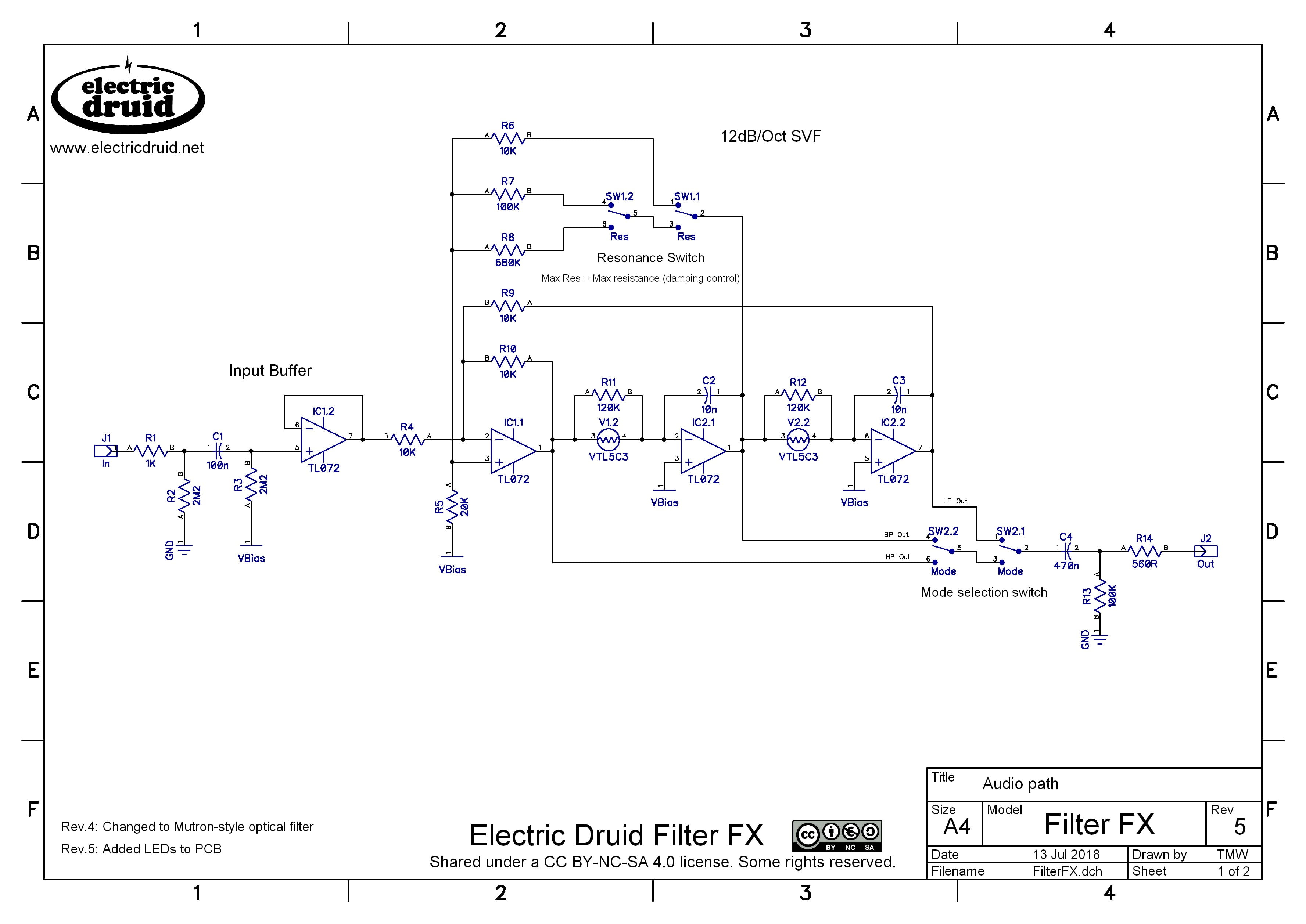
The schematic is pretty straight-forward, and will be familiar to people who’ve studied state-variable filters like the Mutron. At the input we have a simple unity-gain buffer IC1.2 to provide a good input impedance and prevent tone-suck. Then IC1.1 acts as a differential mixer, mixing the input with the two feedback signals from the next two stages. IC2.1 and IC2.2 are op-amp integrator stages, with their frequency controlled by the two vactrols. Basically what happens is that the vactrols control the rate at which the two caps C2 and C3 charge up. By the magic of analog computing, the result of all this is that we have lowpass, bandpass, and highpass outputs available from the two integrators and the mixer stage. The Mode switch selects between them and the signal is taken to the output. Since the audio path is pretty simple and doesn’t include huge gain (except for perhaps on the highest resonance setting) the pedal is quiet.
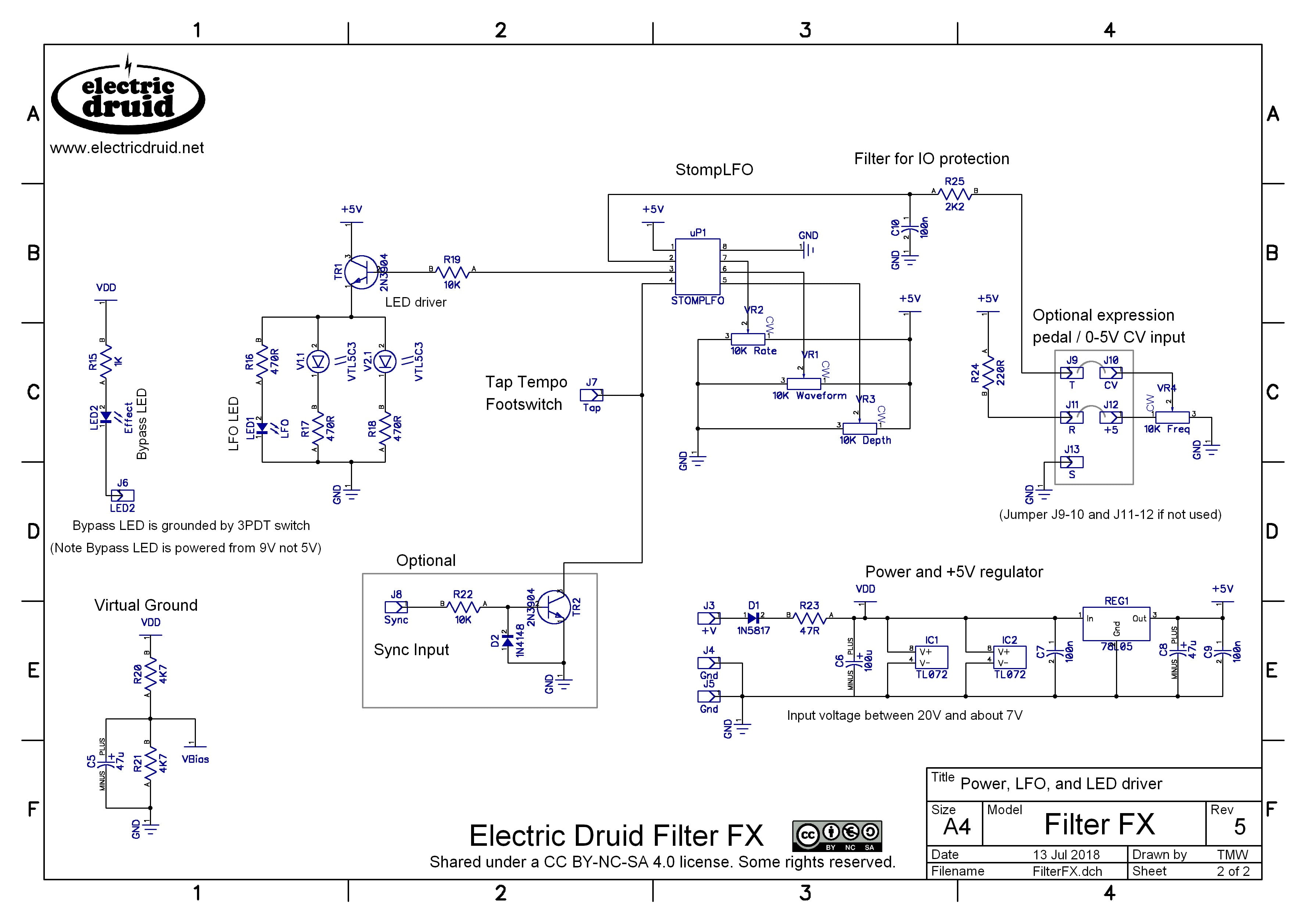
The second page of the schematic is dedicated to the LFO and the power circuit. The LFO is very simple since all the hard work is done by the STOMPLFO firmware. The PDM (pulse) output from the chip is used to drive the two vactrols and the LFO LED. The Tap Tempo foot switch simply grounds pin 4 of the STOMPLFO, and the optional Sync input allows incoming clock pulses to do the same thing, whilst protecting the chip from negative or over-voltage situations.
The power circuit is standard stuff for a stompbox, with a series diode D1 to protect against reversed power connections, and R23/C6 to provide some power smoothing to prevent hum. REG1 gives us a stable 5V supply for the STOMPLFO processor.
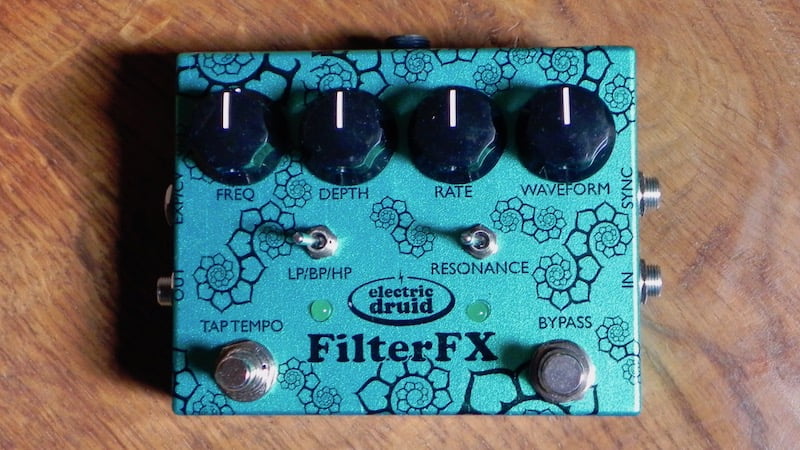
There was a thread on DIYStompboxes about the development of the FIlterFX pedal a while ago if you’re interested and want to see what the prototype looked like. The final unit (fully tricked out with Sync and Expression/CV inputs) looks like this:

Ok, so what do I need to build one? PCBs and parts for this project

Pop over to the shop and grab the FilterFX PCB+Parts set, and the FilterFX pot set. The first includes the PCB, the StompLFO, the two unusual three-position switches, and two VTL5C3 vactrols. The second is a full set of pots for the project.
The most important document you’ll need is the FilterFX construction guide. The Enclosure drilling template comes in handy later on too.
Unfortunately the large amount of hardware and special parts required for this project (two footswitches, up to four jacks, two toggle switches, four pots, and a couple of costly vactrols) means it’s not a cheap build, but you probably won’t find many commercial alternatives with similar features for much less either. At least we can bulk-buy the parts which helps.
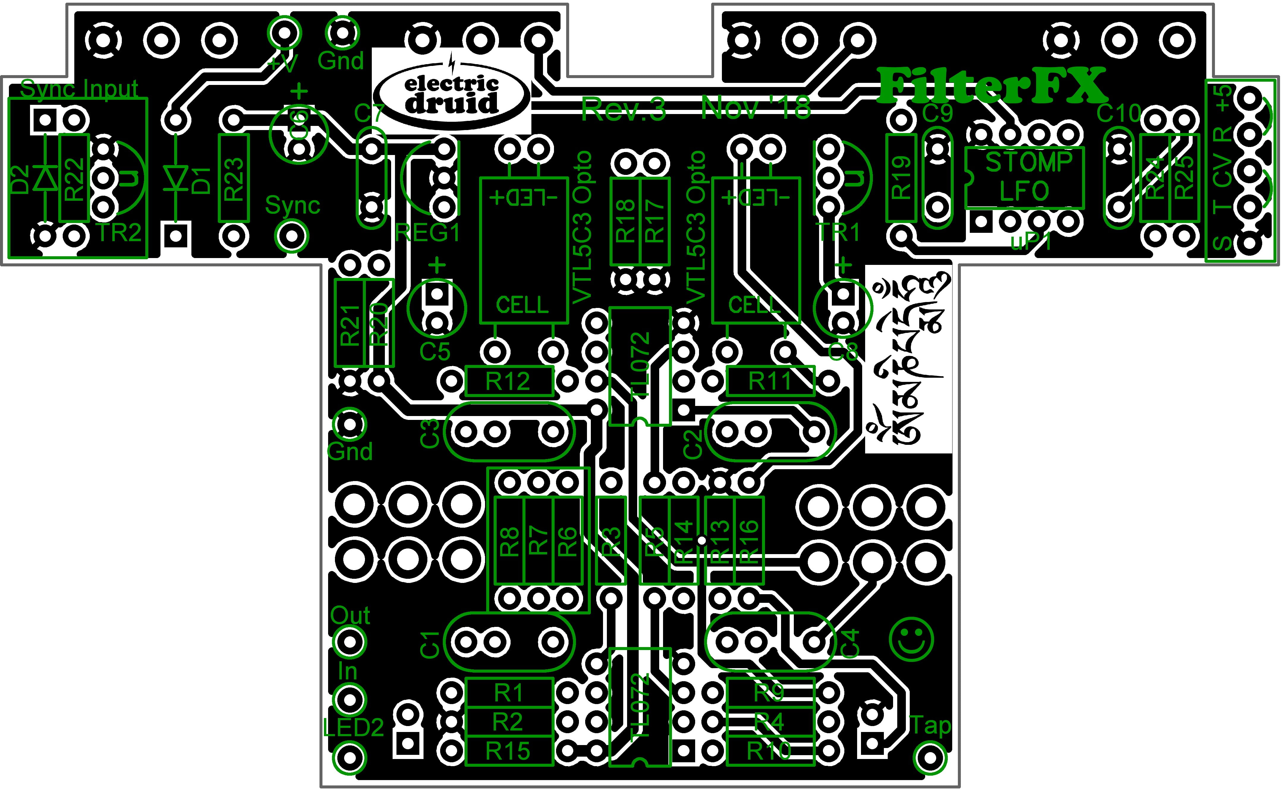
The photo is the latest Rev.3 PCB, which allows for caps with a lead spacing of either 5mm/0.2″ or 7.5mm/0.3″ to be used to make life easier for DIY. For the build above I used my favourite Wima box film caps, which have a 5mm spacing.
The PCB measures 112x68mm. It is designed to fit into a Hammond 1590BB enclosure in landscape format. The PCB-mounted pots make the build easier.
Project files
Here are the full details if you want to tweak the code, do your own PCB, or otherwise experiment with it.
FilterFX files
- Rev.5 Schematic (Page 1)
- Rev.5 Schematic (Page 2)
- Rev.3 PCB Reference Designators
- Rev.3 PCB Component Values
- FilterFX enclosure drilling template
- FilterFX construction guide
The STOMPLFO eight waveform LFO chip with tap tempo
- STOMPLFO.ASM code
- Assembled STOMPLFO.HEX code from the above to program into a 16F18313 chip
- Datasheet for the STOMPLFO chip
Since the code is provided above if you’re familiar with a bit of PIC programming you can tweak the waveforms or the frequency range for your own purposes.
Feedback and comment
As ever, any feedback about the project is appreciated. Please get in touch on the contact page, or comment below.

FilterFX by Tom Wiltshire for Electric Druid is licensed under a Creative Commons Attribution-NonCommercial-ShareAlike 4.0 International License. Here’s the legal stuff.
Filter Fx. Wonderful bit of kit as always
I like this one a lot . Sounds excellent and very versatile . Tough competition for all things Meatball . To me , this one’s better .
Is it possible to mod it to have a jack with only the CV as output to use it for other devices? And voltage would it be?
The FilterFX isn’t ideal for this since it uses the digital output from the StompLFO chip to drive the vactrols directly, rather than turning it back into an analog voltage. So in that sense, there is no CV to output.
However, that said, it wouldn’t be too hard to do. You could probably add the 4 components for the passive filter (check the StompLFO datasheet) on the output jack.
Alternatively, it’s also very simple to knock up a quick StompLFO circuit on a bit of stripboard to make a CV-producing device to control other pedals. Again, the circuit is in the datasheet. The “minimal” version is only the StompLFO chip, 3 or 4 control pots (you can drop the 1K/100n filters – not essential), 3 caps and 2 resistors (100n decoupling round the chip, and passive output filter), plus the 5V power supply (another 7 parts, but many are standard to all stompbox circuits). The circuit is the same for the ONESHOT chip too, so you can simply swap the chips over and experiment with that as well.
Can this be modded in any way to add envelope following to this one , so you can choose between that and the LFO ?
Yes, it’s possible. You could pick up the input signal after the input buffer (IC1.2 pin 7) and feed that to the envelope follower. The only quirk is that you ideally need an envelope follower that provides a PWM output that could drive the LED. You could add a PWM generator to a standard env follower, but it’s a few more parts (high frequency triangle wave oscillator and a comparator is the typical way).
HTH,
Tom
If you do a second version of this pedal with a stock envelope selectable mode it would be the perfect filter pedal. It sounds amazing!
Thanks! I’d like to try and add an envelope mode one day.
Sorry , a bit late but these are crazy times . Thank you for the advice . I’ll try this as soon as possible , but it will depend on how fast I can get the parts together . Been waiting a month now for an order from my supplier , so that is not exactly encouraging . Think this is one of the finest filters around .
Hi! I am just going to put this together over the next few weeks now that the PCB and parts have arrived. I wonder is there any simple mod that I could do to make this switchable into a tremolo?
It might be possible, but “simple”? No, probably not. Sorry!
I do have some StompLFO tremolo designs in the works though. Have a look at this:
https://www.diystompboxes.com/smfforum/index.php?topic=124744
Could your ENVGEN 8C VCADSR Envelope Generator be used for that ?
In theory it could. In practice, getting reliable gate pulses from a guitar signal is not simple. Plus like that, you’d lose the ability to control the dynamics, since you’re replacing the guitar’s actual volume envelope with a new one. So yes, it’d work, but I’m not sure it’d be that great. Maybe I should try it before I rule it out though.
I use it with my synths and it sounds amazing. I love it!
Hi, just wondering if dry blended pot can be added to the pedal to mix the input signal with the effect?
Yes, it certainly could be. The question is how complicated you want to get with it. You could add a full inverting op-amp mixer, with both wet and dry controls, or just a dry blend control, or you could go with a simple passive crossfade from the input buffer output to the filter output.
This is a very fun project with a lot of useful sounds. Is there a simple way to boost the output volume for the effect? The perceived loudness drops a lot when using the bp or hp settings for the filters.
Yeah, a volume drop is typical because you’re cutting so much of the sound away. The amount of volume you lose depends on the filter settings. Unfortunately there isn’t really a simple way to just tweak a couple of values and get more volume. It’d be possible to stick a simple boost circuit on the end, of course. That’s one way. At the risk of some distortion, as an alternative you could modify the input buffer to have some gain (non-inverting op-amp). Filters often sound great with dirty inputs, so it might not be bad, but it might not be the sound you’re after.
If you wanted a boost, something like this would do it:
Electro Harmonix LPB-1 booster
You could drop R13 and R14 from the FilterFX schematic and also drop R1 and C1 from the boost. Our C4/470n takes over from C1 and it’s all good.
I have built an :PB-1 boost before and I am familiar with it. I’m also thinking that the Jack Orman mini-booster would be an easy add-on as well. not a huge issue in either case. thanks again for a really well-done filter project.
tried the LPB-1 but had some noticeable hiss added in with the boost. put in an amz mini-booster and got a great clean boost from it.
Hi Tom. Another really nice project. I was planning to integrate one of your lovely stompLFO inside a Ms20 filter “clone”… Now i’m considering your design.
A question : is it possible to rise the value of the resonance (ie replace resistors by a pot) to get the same self-oscillating character of a Ms20-ish filter ? And would it sound good, with TL072 ?
Thanks !
Nico
Hi Nico,
Yes, you can replace the resistors with a 1M pot for the resonance. The filters I’ve built so far don’t *quite* oscillate (because of the variation between the vactrols, I expect) but if you wanted full oscillation you could experiment with decreasing the value of R9/10K to increase the lowpass feedback gain. That signal is what produces the resonance, and the Bandpass feedback path is then used to damp it, which is why the resonance control works “back-to-front” e.g. bigger resistance = less signal = less damping = more resonance.
Thanks Tom. For the resonance pot, which do you think would work best ? Lin / log ?
Hi Tom,
Just wondering if you could offer a little more detail regarding the pot-mod for the resonance control. I have found the resistors that control resonance that need to be removed but I’m having trouble figuring out how to wire in the 1M pot. Where do the three wires from the pot need to go on the PCB for this to work properly? Thanks for your help.
Ben
Hi Ben,
You’d have to:
1) Remove the three resistors 10K, 100K, 680K from inside the little box on the silkscreen.
2) Swap the resonance switch for a pair of wire links to hard-wire it into the “High” position.
3) Use one pot outside lug and the centre lug and wire those to the 680K resistor position. If the pot works backwards, use the other outside lug!
I hope this helps, good luck!
Hi Tom! I want to integrate it to an MS20/lm13700 filter. I tried conneting pin5 of taplfo3 (pwm out) to the middle lug of freq pot but i lose high end. Am I doing this right? Because I love the way this one sweeps, cant get it to work the same way with my 13700filter.
Thanks!
Gus
Sorry Gus, I don’t understand what you’re describing. Get in touch via email and we’ll discuss it!
Hi Tom, was going to send you an email but thought others might benefit from your reply. Can I just use a 3.5 mono jack for the CV/expression pedal input (obviously to control with CV rather than a pedal). If so how should that be wired? Also with adding CV inputs for the functions on the stomp LFO chip should I just be wiring the jacks straight to the chip or is there a better way to do that?
The best would be a 3.5 mono jack with a normalled connection. The signal from the pot’s wiper would go to the normalled connection so that when a CV jack is inserted, it breaks the connection. The ground is simple.
Note that the input I intended as a CV input includes a RC filter R25/C10. The lowpass filter is not essential, but the series resistor of 2K2 absolutely is, because this limits the current that can flow through the StompLFO’s internal protection diodes if the input CV goes outside the 0-5V range. So definitely include a series resistor if you add CV inputs to other inputs.
HTH!
Thanks Tom! That all makes sense.
Hi Tom. Sorry to hijack this, but could you explain to me what the 220R R24 in Series from 5V to the TRS jack does? Does it provide some limit together with the 10K Freq Pot?
Hi Max,
It’s there to limit the current that can flow if the +5V is shorted to ground briefly when a jack is inserted – or if someone inserts a mono TS jack instead. It’s just for safety, basically.
Hi this looks and sounds great. Will the version of PCB and additional parts be available soon to purchase? I’m wondering if i should wait or try and source those parts myself. Thanks!
Yes, they’re available:
FilterFX PCB + Parts set
Tom it looks like it says the PCB + parts kit is unavailable when i go to that page. Maybe I’m missing something?
Any chance anyone knows of a filterFX Tayda drill template?
If not, I’m going to have a try at creating one (I’ve never created one before though so it might end in disaster). However, I noticed the dimensions on drill template don’t seem to add up to the 1590BB dimensions exactly (if I add all the y or x dimensions they don’t equal 119.5mm and 94.0mm). They are off by a little bit. Any chance you could update Tom? It probably doesn’t really matter but I’m an engineer so I can’t handle non-exact thing. Ha. If you don’t update I’m sure the existing dimensions are close enough but just thought I’d ask.
Thanks!
The problem is that there are several versions of the “standard” 1590BB box, Peter. There’s the official Hammond boxes, there the Eddystone versions (which are made by Hammond, but somewhere else) and then there are clones which are “equivalent” but often differ by a couple of mm.
The important thing is to work out the centre point for the box you’ve got and work outwards from there!!
Oh! Multiple versions. Ha. Ok roger that. I’ll see what I can come up with. Thanks!
What adjustments would I need to make for this to work with some hand rolled vactrols using this LDR?
https://www.taydaelectronics.com/datasheets/files/A-5795.PDF
Basically, you can adjust it for *any* LDRs by adjusting the C2/C3 cap values and the R11/R12 resistor values. How it works is:
You turn the Depth pot down to zero and the Freq pot down to zero, and then change the caps until you get the lowest filter frequency you want. Changing the Resonance switch can make this more obvious. 22n takes you another octave below 10n. 4n7 is an octave higher. What is most suitable depends on the LDRs. Adjust to taste.
Once you’ve got the lowest frequency sorted, you keep the Depth pot at zero, and turn the Freq pot to the highest setting. Again, more resonance can make this more obvious. Then you change the R11/R12 value (currently 120K) to give you the highest frequency you want. Again, this is largely a question of taste, and it’s possible to set the sweep range either wider or not-so-wide.
I set it up for something I thought was fairly flexible, but not extreme, with the Xvive VTL5C3 vactrols I had. Other vactrols or hand-rolled LED/LDR combinations might well need other values, so experiment. As you can see, it’s not hard to do.
I just built a second FilterFX and was comparing it to my first one (I got the LDRs from here for both of them btw). The high freq on the second one is so high/weak it’s almost not audible with the dept at min and freq at max even at higher resonance settings. In general at more usable settings the pedal is much quieter (where the middle resonance setting on second pedal is more like the right setting on my first build).
I thought it was broken it was so different. I swapped the TL072s and STOMPLFO chips between the two but that had no impact. I was about to send you an email and then I saw this! I’m guessing normal LDR differences are causing this. This is great info to know! I might suggest putting it into the construction doc even. Perhaps even suggesting a trimmer pot for the resistors for those that want to be overachievers? 🙂 Not sure if that is practical or worth it though without a new PCB layout to accommodate trimmers although there is open space around R11/R12.
Now the real question is which one sounds better? I’m not sure…. ha. I do think the new one is a little to weak when it is at the high freq values and low resonance, so maybe I’ll try to tweak the resistors. But the new one does have a bigger sweep/depth it seems, I’m guessing due to this difference. I guess perhaps we should just say it’s like the early fuzz pedals and you have to find one you like! 🙂
Thanks for the great pedals Tom!
To be honest, that doesn’t sound quite right. The symptoms you describe sound like there’s something up with the filter. I’m not surprised that swapping TL072s and the StompLFOs made no difference, though. Perhaps one of the feedback paths isn’t quite right? Get in touch and we’ll discuss it.
Hi Tom. Is there datasheet for the Salecom T812 somewhere, or a explanation of the internal connections? I can’t find it, and it will help me understand the wiring of the mode switch. If you can help me in someway, it will be nice. Thank you
Hi Laurent,

The switching is a bit weird for these On-On-On switches, I agree! It’s much easier to *see* than to explain, so I’ve done a diagram showing what happens with the toggle in each position:
Perfect! Thank you
Finished this build a few weeks ago and the pedal has quickly earned a spot on my board. I really like the more subtle settings added to almost anything I play. Especially combined with drive. Adds a lot of depth to my tone. I really enjoy the pedal. I placed it in the middle of my board so I can add drive before or after. Both of which sound great to me.
Hey there,
Thanks for developing this kit. I just had my second cup of tea and decide to do a quick power test. Each op-amp sockets returns a 9V power however the STOMPLFO socket only returns a 2.88V power instead of the 5V announced. I checked the soldering which seems correct. I don’t really know what else to check, maybe you can help me ?
Thanks 🙂
The classic error is to put the 5-volt regulator in back-to-front. I *know* it should be obvious, but I still do it!
Aside from that, a short somewhere might cause a low voltage.