
In the last six months, we’ve been very busy here in the Druid workshop, developing and testing new versions of our PIC-based chips. This work is now complete, so I’d like to introduce the new chips.
Why bother? What was wrong with the old ones?
Ok, there wasn’t anything much wrong with the old ones, but things have moved on since 2008 when most of them were originally developed – ten years ago already! Most importantly, Microchip have released a newer range of processors, the “enhanced” 16F series chips. The original chips mostly used the 16F684 processor, which could run at 20MHz, but required an external crystal to do so. The newer chips can run at 32MHz, and no longer need a crystal. This saves parts and cost, and frees up a couple of pins for extra features too. This provided the motivation for a comprehensive update.
The new designs increase the size of lookup tables, with data tables moving to 16-bit resolution and including interpolation for super-smooth results. The extra speed moves the sample output rate up to 31.25KHz, so there is an improvement in quality.
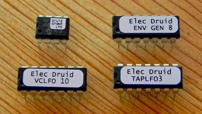
TAPLFO3D – Tap Tempo LFO with many features
The original TAPLFO2D chip was one of our most successful and popular designs, and has inspired a range of exciting and versatile pedal projects.

The new chip adds plenty of new features:
- Smoothing filter to reduce clicks from sharp waveform edges
- Two sets of eight waveforms for sixteen separate waveforms in total
- CV invert configuration input to make life simpler with CV mixers
- Unipolar or Bipolar output selection

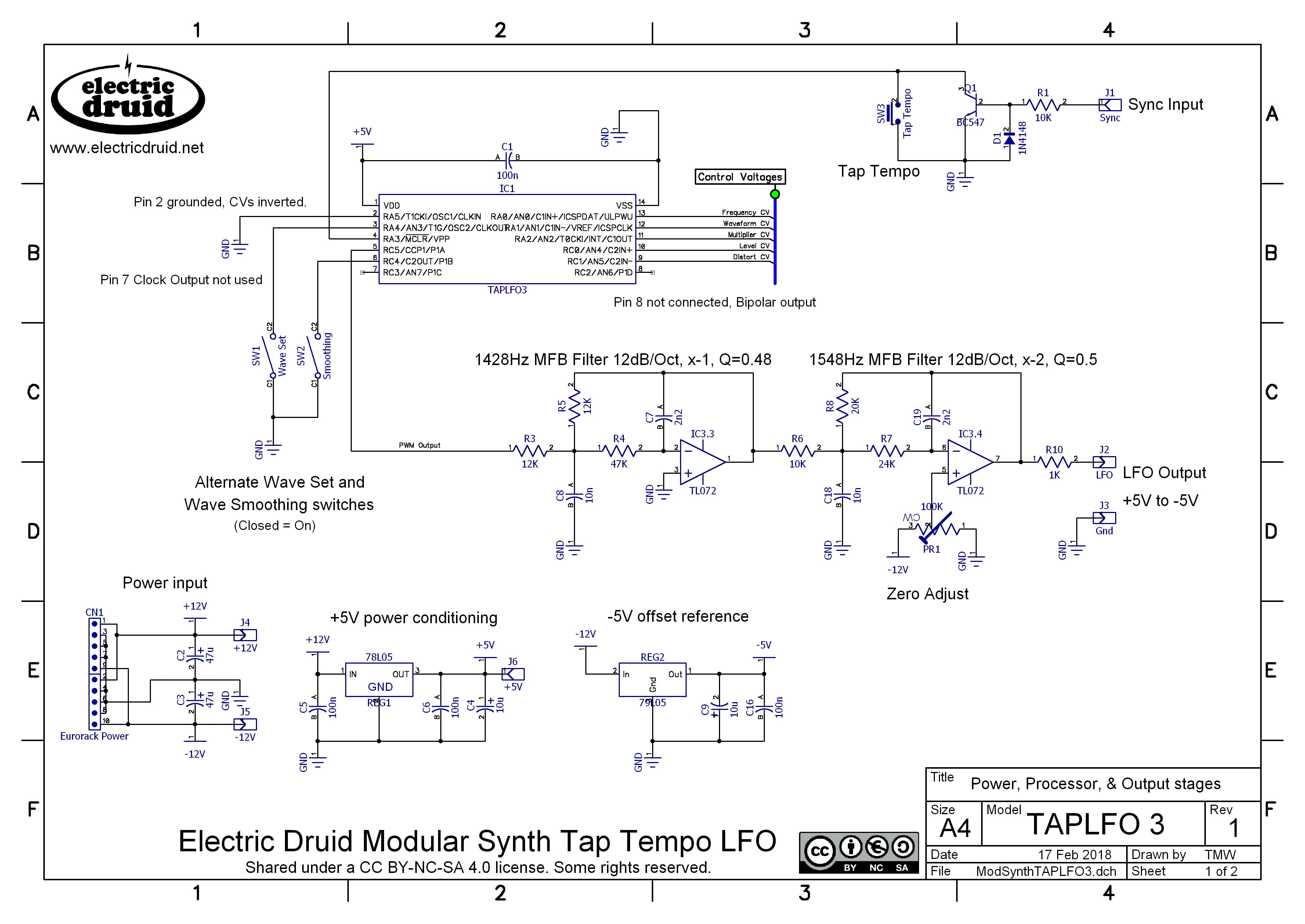
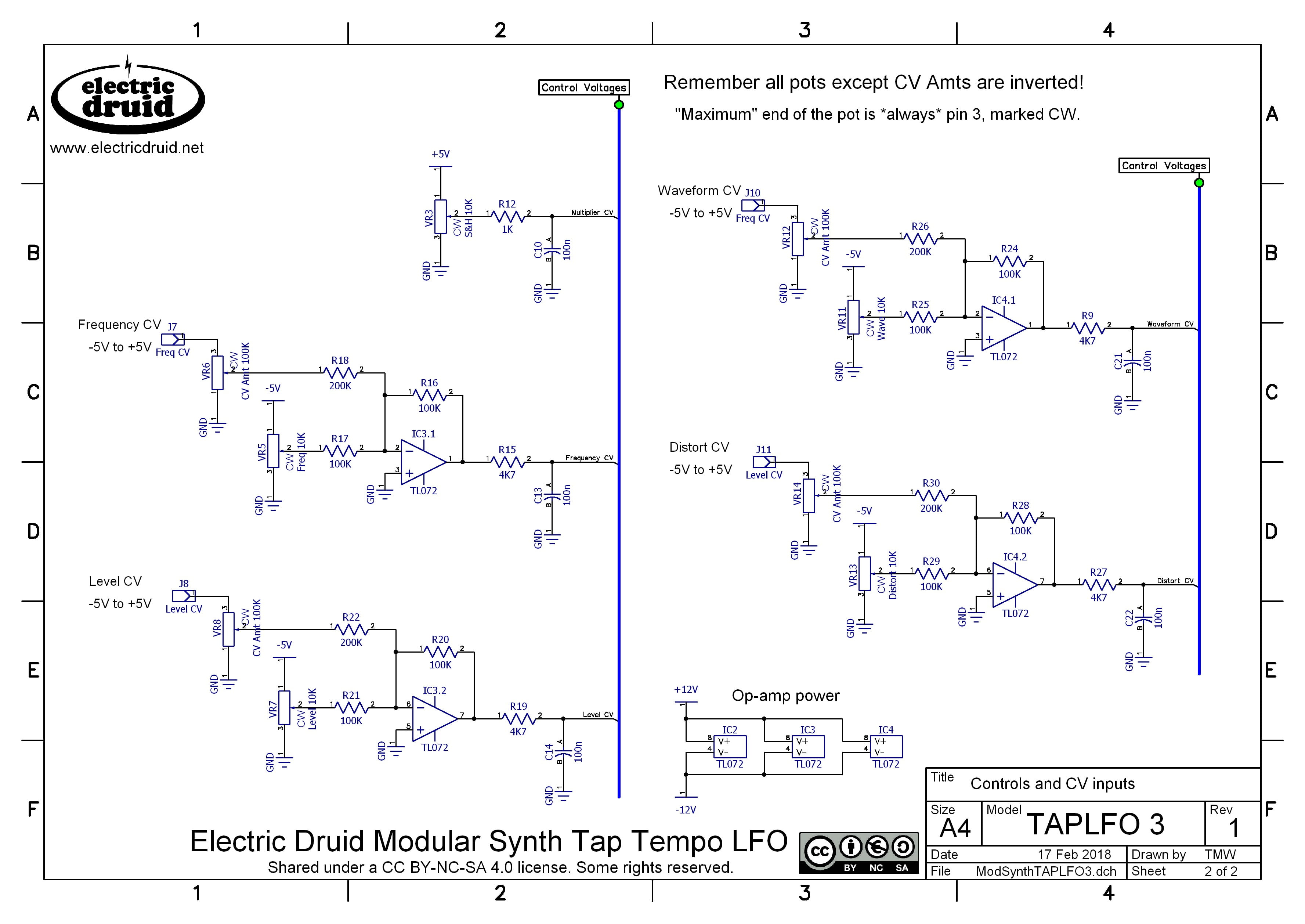
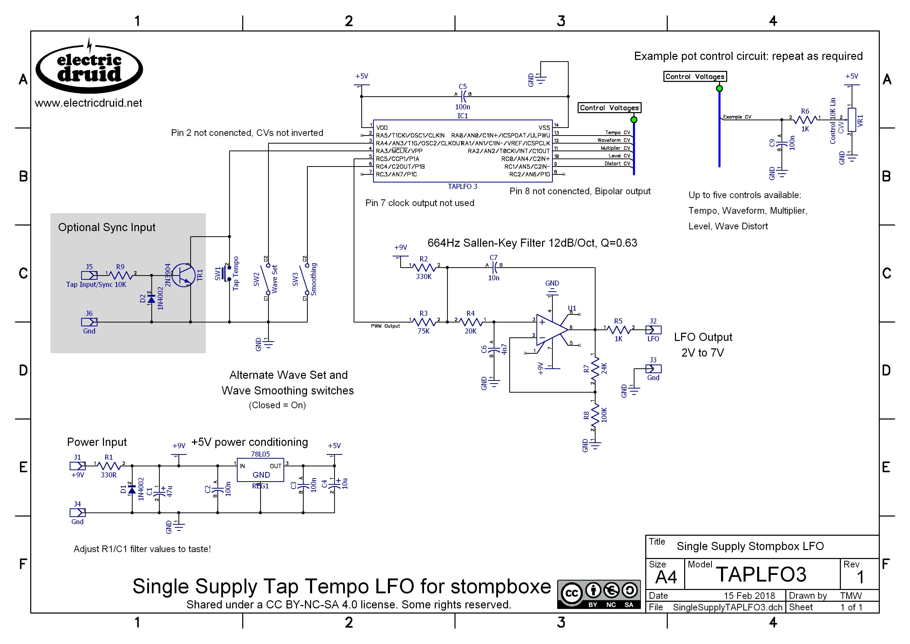
TAPLFO3D details
- Voltage-controlled low frequency oscillator PIC 16F1824 ASM code TAPLFO3D
- Assembled TAPLFO3D.HEX code from above file
- Modular Synth Tap Tempo LFO Circuit Diagram Page 1
- Modular Synth Tap Tempo LFO Circuit Diagram Page 2
- Single Supply Tap Tempo LFO
- TAPLFO3 datasheet (includes circuit diagram and chip pinout)
TapLFO3D – some bug fixes
The TAPLFO3 chip released in February 2018 had a small bug in one of the arithmetic routines that caused it to run slightly slow when compared to the tapped tempo, especially at slower tempos. This has been fixed, and the switch debouncing has also been improved. You can read more about it here if you like. In January 2023, we discovered that in certain circumstances, the Clock Output on the 3C chip dropped output pulses when used with a stream of sync input pulses. The new 3D version fixes this minor bug.
STOMPLFO – 8-pin tap tempo LFO for smaller spaces
The StompLFO design is a simplified and lower-cost version of the TapLFO designed to fit in an 8-pin chip. As such, it can replace the typical dual op-amp Schmitt trigger/integrator LFO design that you see in a million stompbox and guitar pedal circuits.

One significant difference from the other LFO designs is that it uses Pulse Density Modulation (PDM) instead of Pulse Width Modulation (PWM) for the output. This enables the output frequency to be much higher (2MHz instead of 10’s of KHz) and that means simple RC filters can smooth the output easily without losing any waveform detail.

The Offset CV and Depth CV interact in an interesting way to allow the chip to produce bipolar or unipolar waveforms of either polarity. Furthermore, in between these extremes, it responds sensibly to increasing depth, making it easy to set up for a given situation.
The diagram above shows the output for a Triangle wave with 0-5V Depth CV (in blue) and various Offset CVs (in red). The graphs show 0V Offset, unipolar positive “bottom up” depth control, 5V Offset unipolar negative “top down” depth control, 2.5V Offset bipolar “middle outwards” depth control,and finally 1.25V, which starts off bipolar until the output runs out of range, and then increases in a unipolar fashion. This allows full depth control without ever going beyond the lower (or upper) limit.
STOMPLFO details
- Voltage-controlled low frequency oscillator PIC 16F18313 ASM code STOMPLFO
- Assembled STOMP.HEX code from above file
- STOMPLFO 8-pin Tap Tempo LFO Circuit Diagram
- STOMPLFO datasheet (includes circuit diagram and chip pinout)
VCLFO10 – A fully voltage-controlled LFO with two sets of eight waveforms
The VCLFO was the first significant PIC project I ever coded. As I learned more and more I was able to add more features and make improvements, which is why it was onto version 9 before it made its public debut!

In the ten years since then, I’ve learned far more, and the new VCLFO10 takes advantage of this and does many things I wouldn’t have thought possible originally, like the random slopes waveform. Some of these new waveforms have already been put to good use in the Benidub DS71 Dub Siren. Pop over to their site and have a listen.

So, what have we added? Here’s the improvements and additions:
- Increased waveform resolution and interpolation
- Faster output sample rate of 31.25KHz
- Range CV to select one of four ranges: 0.05Hz to 12.8Hz, 0.1Hz to 25.6Hz, 0.2Hz to 51.2Hz, 0.4Hz to 102.4Hz
- Smoothing filter to reduce clicks from sharp waveform edges
- Two sets of eight waveforms for sixteen separate waveforms in total
- CV invert configuration input to make life simpler with CV mixers
All in all, it’s a big step up.
VCLFO10 details
- Voltage-controlled low frequency oscillator PIC 16F1825 ASM code VCLFO10
- Assembled VCLFO10.HEX code from above file
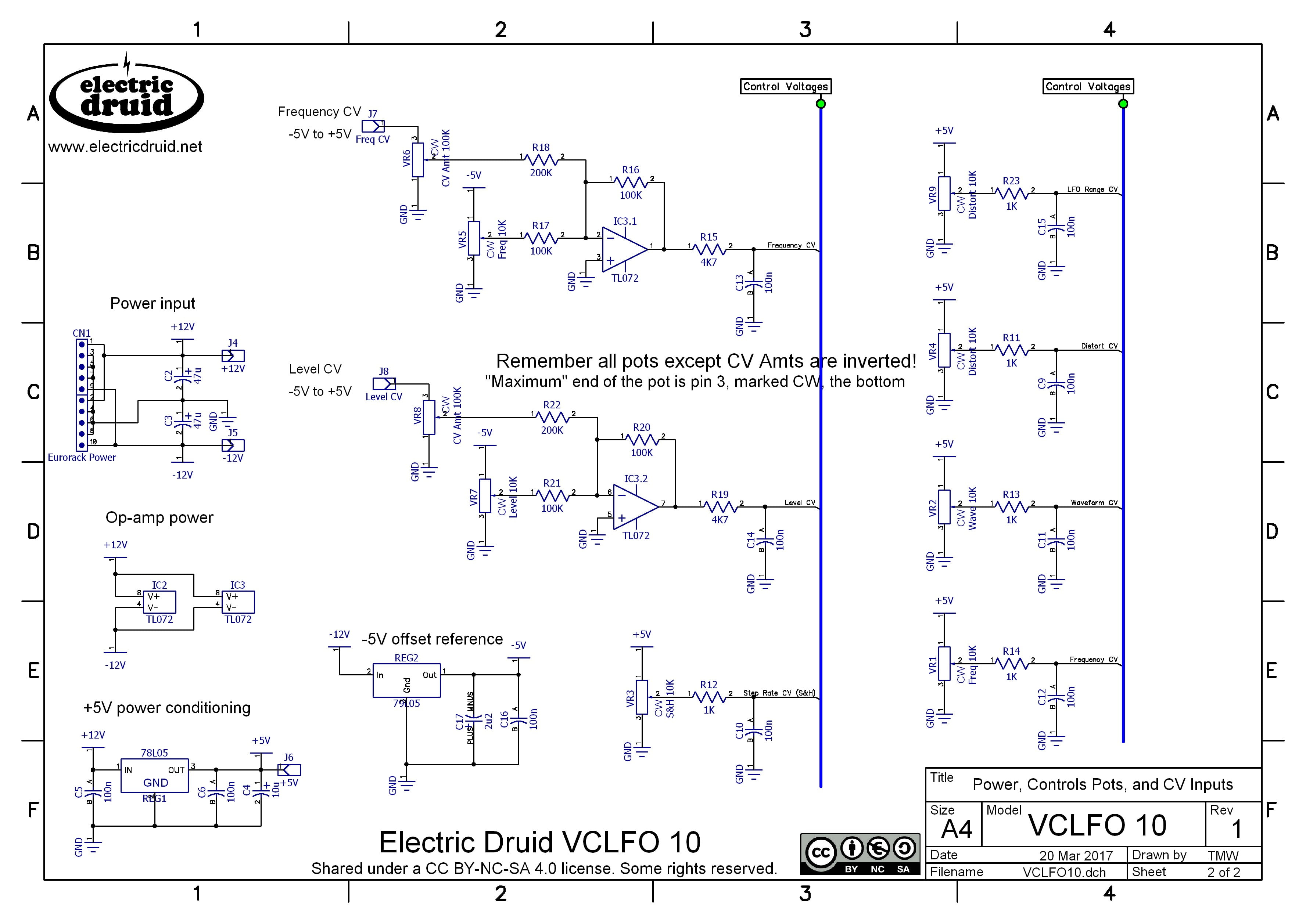
- Voltage controlled VCLFO circuit diagram Page 1
- Voltage controlled VCLFO circuit diagram Page 2
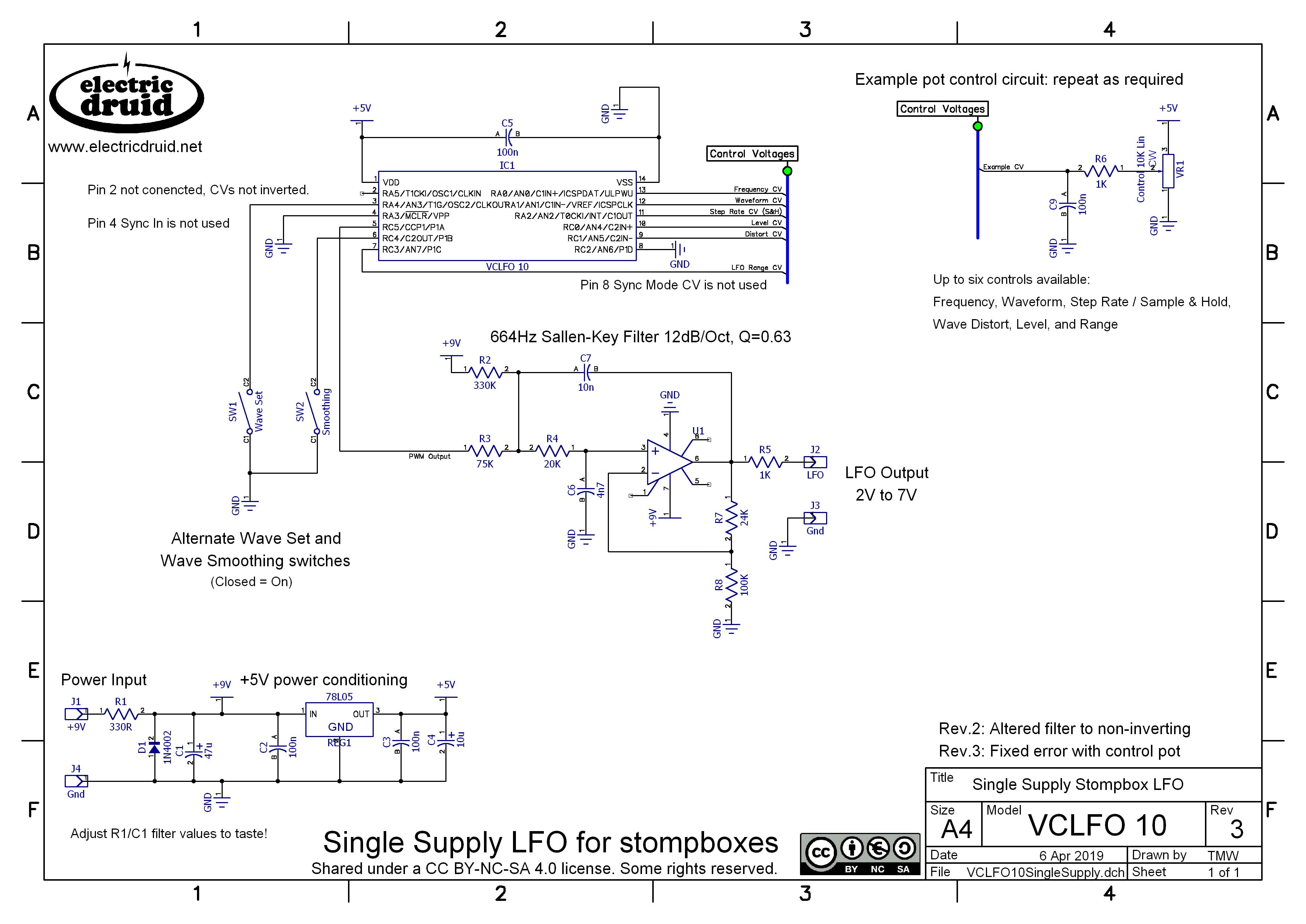
- Single Supply VCLFO Circuit Diagram
- VCLFO10 datasheet (includes circuit diagram and chip pinout)
ENVGEN8C – a voltage controlled ADSR envelope generator with looping features
I was never entirely happy that I had to have two separate designs to include the looping features I wanted on an envelope generator. The VCADSR 7B had Gate and Trigger inputs, and the LOOPENV 1B replaced the Trigger input with a Mode CV input that allowed selection of two looping modes or standard ADSR behaviour. It would have been possible to move the code to a 20-pin chip, but that would have been overkill.
The new chip allows me to finally solve this problem neatly, and the ENVGEN 8 has both Gate and Trigger inputs, and the Mode CV and looping features of the LoopEnv.

The other major improvement is that it now uses an on-chip 10-bit multiplying DAC. This not only means that the need for post-chip filtering is much reduced or eliminated, but also that the Level CV control can be done without loss of resolution. The output remains at 10 bit resolution at low levels as well as high.
Additionally, the sample output rate has gone up to 31.25KHz, the tables have been improved, and we’ve added a Punch feature which gives your shortest envelopes more thump.
Example Output
The following diagram shows some example outputs with the three different modes (MODE CV) and the effect of the LIN/EXP selection input to select exponential or linear shapes. The first two modes respond to the GATE and TRIGGER input, but the LFO Looping mode runs constantly irrespective of Gate state.

ENVGEN8C details
- Voltage-controlled VCADSR envelope generator PIC 16F1764 ASM code ENVGEN8
- Assembled ENVGEN8.HEX code from above file
- ENVGEN8 ADSR and AS3360 VCA Circuit Diagram
- ENVGEN8 datasheet (includes circuit diagram and chip pinout)
- Example modular synth envelope generator schematic
ENVGEN8C – a bug fix
EnvGen8C fixes a few minor problems. The previous chip wouldn’t go to the release stage correctly if the Mode was switched with the gate still high, and wouldn’t power up correctly if the Gate was high (which is an over-voltage condition – not good!). The new code fixes these annoyances.
Final Note
As ever, any comments, ideas, or corrections are appreciated. Please get in touch through the contact form. Thanks and enjoy the new chips!

The TAPLFO3, STOMPLFO, VCLFO10, and ENVGEN8, projects, code and schematics by Tom Wiltshire for Electric Druid are licensed under a Creative Commons Attribution-NonCommercial-ShareAlike 4.0 International License. Here’s the legal stuff.
Incredible, thanks sooooo much for sharing, this page is a goldmine!
With all those new chips around I might finally go for that DIY Polysynth..
Anyway great work, keep it up!
Great to see guys!
Tom Wiltshire, thank you ever so for you post.Much thanks again.
Gracias por compartir estos diseños. ¡Eres uno de mis ídolos diy!
looks great! Was about to order a while ago and saw that the previous chips were discontinued, so now I am ready to go …
One question: can the small 8 pin stomp lfo also used in a modular setting? Using a similar schematics as the larger lfo? I am looking for a small and simple lfo to use in a modular synth (also a replacement for the usual analogue square/triangle) with minimal circuitry. Only CV input would be the tap tempo. But the output should be bipolar -5V…5V. Is it recommended to use the filter example from the other lfo? Or are there simpler solutions? Will there be more example schematics?
Thanks!
Hi,
There’s no problem using the StompLFO in a modular. Yes, you can use the same CV input from the TapLFO schematic, but you’ll need to add an inverting stage as well – there’s no software “CV invert” option on the StompLFO.
For the +/-5V output, you can use just the second stage of the TapLFO’s filter – the 1548Hz part with the offset and gain. There’s no need for a 4 pole filter with the StompLFO’s PDM output.
HTH,
Tom
PS: There might be some more example schematics in due course…I’ve got a few things up my sleeve!
Hi Tom
Really good update.
I must say, your ‘creative commons’ sharing model is a wonderful example of the best of the synth community.
Great work!
Best Regards
Love this new ADSR, but got a problem the time settings, just work on a limited part of the pot, about from around the middle, it will not trigger the ADSR cycle outside this area,when I am using the gate input, but seems to work on trigger input.Will be thankful if you know why. And a great thank you for publishing the code!
This is a problem. It shouldn’t behave like that.
If you’re just using the Gate input alone, you need to connect the Gate and Trigger inputs together (e.g. feed the Gate to both inputs). It won’t work correctly with the Trigger input left unused.
If you have more problems get in touch and we’ll get you debugged!
Hello Tom,
I’m planning to build a TapLFO using the schemas given in the datasheet and adding a few more tips like a 7-segment display that would display values for multiplier and LFO waveforms. Maybe for Distort as well, but I have to think about it.
I saw that in the TAPLFO3 application notes, the Waveform CV input can be powered in + 5 / -5V CV with a max amplitude handled by the VR12 potentiometer. In addition, manual adjustment is possible with the VR11 potentiometer. This one is supplied with -5V / 0V. What makes sense since IC4.1 is mounted in inverting amplifier. Yet (sorry for the silly question) what happens when VR11 sends 0 volts and VR12 receives, say, + 5V? The output of the amp comes out of -5 volts, right ?
How does this affect the RA1 input of the MCU (Pin12) ?
What happens is that the internal protection diodes start to conduct because the input has gone outside the supply voltage of the PIC. To protect the diodes, it’s important to limit the current that can flow. That’s why there’s a 4K7 resistor in series with the input – it’s not *just* there to act as an RC filter, although it does that too.
Also, you’ll notice that the external CV inputs are shown with a 200K input resistor, so they are reduced to a +/-2.5V range. That still allows the CV input to cover the entire range of the control, but it also helps limit the amount of current that can flow in the diodes when the input goes outside the usual range. We used a circuit like this on the Frequency Central Waverider VCDO module, and as far as I know no-one has ever blown up one of the CV inputs, so it seems to be reliable and safe.
Good luck with your project – multiplier and waveform displays sounds great!
Hello Tom
Is it possible to have a software LFO invert on TAPLFO or stompLFO on an unused pin ?? For example if I wouldn’t want to use the Clock output or LED output pin would it be possible to assign that pin as LFO invert?
Yes, that would be possible. It’s easy to invert the output (just flip the values before they go out), and to do that based on the state of a pin is also very simple. The only awkward bit is setting up the pins correctly so that you’ve got inputs and outputs in all the right places! Email me if you need help with it.
Super thank you Tom!
I’ll try to come up with something and if I get stuck I’ll shoot you an email
Cheers
I’ve built three 8-pin stomplfos into my synth design but they don’t always start oscillating at switch on. I typically have to re-start the synth 4 to 6 times to get all three LFOs running. Once running they stay running. I’m using a large linear +/- 15V PSU and each stomp ic has a 7805 regulator, 10u electrolytic and 100n ceramic on its pins. How can I get all three to start every time?
Hi Steve,
Sorry to hear you’re having trouble. To be honest, failure to start up is not something I’ve ever seen but get in touch directly and we’ll see if we can’t get you up and running.
Tom
False alarm – the problem is elsewhere in my synth – it seems that connecting USB to the Arduino Due is somehow preventing the LFOs from starting up. Maybe the USB is trying to power the whole synth when its psu is off? Anyway, not electric-druid’s problem. 🙂
I can recall from an ancient epoch (1980s) trying to design and build these types of functions with discrete components (gasp)
Somewhere in the future I thought, maybe some of these circuits will be expressed as ICs . . . and here we are.
Can i use stomplfo just as a clock for a cd4040? if so, how? ive tried to use the PDM output as is to the clock input of the 4040 but cant get it to work. 🙁
You could probably use the StompLFO as a clock, but you will definitely need some filtering on the PDM output. Otherwise, you’re not feeding a slow LFO waveform to the CD4040, but instead a 2MHz pulse signal!
Hi Tom,
Would it be possible to use the ENVGEN8C as a drop-in for the ssm2056? Maybe smd with some tinkering?
Thanks!
It’s not a drop-in replacement, but like you suggest it can be done with some tinkering, SMD or not. We had a customer who managed to fix a Korg Polysix that had had all the envelope chips removed by rigging up a daughter PCB with the EnvGen8 on it instead. So, yes, it’s possible.
I’m trying to compile the StompLFO code, and I keep getting a ton of syntax errors. I’m using MPLAB X 5.45 and the default ASM compiler. I’m assuming the problem is related to my setup in some way. And obviously I’m pretty new to the PIC / MPLAB environment. Could you point me in the right direction in terms of getting the right compiler and/or other environment settings/variables correct? I would love to tinker with the code and test things out. Most excellent work on the code comments, by the way. Thanks for the assistance.
Unfortunately Microchip have just recently abandoned their previous PIC .asm compiler in favour of a new product they’re calling PIC-AS or something. It is not a separate assembler, but rather just a part of the C compiler. It uses a quite different syntax to the earlier compiler, so the code is not compatible at all. This is in many ways a completely crazy move on Microchip’s part since it makes all the code in their own datasheets obsolete, not to mention the enormous amount of PIC code that exists on the web.
I think the last version of MPLAB X that uses the previous compiler is 5.30. Here’s a link to the various versions:
https://www.microchip.com/en-us/development-tools-tools-and-software/mplab-ecosystem-downloads-archive
For the record, I’m currently still using 4.05, although I did install 5.40 briefly on a new computer before I realised the chaos it causes.
HTH,
Tom
Wow, that does sound like a really bad move. I appreciate the help in figuring this out.
Is it possible to update the syntax to conform to the new compiler without rewriting the code significantly? Or is it just such a pain that it’s nor worth it?
It’s possible to rewrite the code, but (I thought) the changes are significant, so it’s a pretty big job. And tedious, to boot!
There’s some stuff online. Have a search for “Converting PIC ASM to XC8 compiler” or similar.
I notice that the values in the control/phase-inc tables have changed from the ENVGEN 7B to the 8C. How is the difference derived, as it doesn’t appear to directly relate to the change in clock freq. from 20MHz to 32MHz ?
It’s more to do with the change of sample rate from 19.5KHz to 31.25KHz. However, I also tweaked the control curve a bit between the two versions. I’m always searching for the best balance between control at the short end and access to longer times, and juggling the amount of control rotation dedicated to each.
Thanks – that makes sense as 31.25/19.5 gives the approx. ratio of the table entries! (I’m looking at porting Jean-Pierre Desrochers “Moog” control tables across from the ENVGEN7 to the ENVGEN8C).
Wouldn’t the little 8 pin PIC with the PDM output be the perfect ic for a little throw in midi2cv solution? That’s something I am looking for since years and I guess a few other people too 🙂
Can you please tell me, on Vslfo10 and Taplfo 3 chips, is it possible to modulate all the waves one by one in a circle?
It’s possible to modulate the waveform CV, but it doesn’t morph from one to another – instead it switches abruptly from one to the next. It would be possible to do this “in a circle” by using a 0-5V ramp wave CV, so that the sequence of waveforms repeated as if they were arranged in a circle.
The only chip we have that can moprh from one waveform to the next is the VCDO. That can run at low audio frequencies, but isn’t brilliantly suited to use as an LFO. Sorry!
The asm and hex files on this page cannot be downloaded?
Sorry about that! We had a problem, now fixed.
Just a slight question for clarification — on the TAPLFO, the unipolar/bipolar setting only matters when the Level is not at full, right? Similar to the interplay between the STOMPLFO’s Depth and Offset?
Yes, that’s true. At maximum level, you won’t see any difference between the two settings.
Thank you Tom for all the fantastic work you put out!
I’m having trouble with the StompLFO I wanted to ask if you’ve seen before. At low speeds high depth the output is ringing on the downward slope. I’m using the Sallen-Key filter from the datasheet. Would you have any advice on how to debug it?
That sounds like there’s too much resonance in the filter, so there’s probably a mistake somewhere since the design value for the Q is only 0.63. Check the part values, and check the soldering on those gain resistors R7/R8. Too much gain there will boost the resonance.
Hi Tom,
Love this website! I had a question about the VCLFO: When using potentiometers for cv control the datasheet shows a 1K resistor between the pot and the cv pins on the chip with a 1nf cap to ground behind said resistor. I’m planning to use rotary switches for range, sync and wave cv. Should I put that resistor and cap combo between the common pin of the switch and the cv pins on the chip, or should the common pin of a rotary be connected directly to the cv pins?
P.S: I’m making gerber files for the VCLFO and VCDO with added display features. Is it okay if I maybe share those online someday?
Kind Regards,
Tim
The 1K/100n from the pot wiper is just a little RC lowpass filter to help keep scratchy noises from the pot out of the CV input. As such, it’s not strictly necessary even for pots. You could leave it off for the switch, I’d say.
Feel free to share any files you’ve done. Those are yours to do whatever you like with, after all. From my point of view, I appreciate people putting in the work to develop stuff around my chips, so thanks.
Hello Tom,
Bravo for all this work! Impressive!
I built a VCADSR with this PIC and your Program, I would like to integrate the velocity of the keyboard, I thought of entering it using CV Time, but this value does not seem to be taken into account when the ADSR sequence is in progress (I modified your software so that the more the voltage is positive on the CV Time input, the longer the times A, D, S and R become);
do you have an idea to achieve this?
I should note, that on my system, the velocity arrives 500µs after the Gate signal.
THANKS.
Kind Regards,
Got
Hi Got,
The Time CV is taken into account every time the Attack/Decay/Release CVs are updated. What I can’t tell you off the top of my head is how often those CVs are updated. “A few KHz” is probably the right answer, but I don’t remember exactly.
Changing the code around so that “More CV = longer times” will give a strange response with a velocity CV- hitting the notes harder will produce a slower attack, the opposite of what we naturally expect. Of course, it might be interesting to experiment with, so go ahead!
HTH,
Tom