
For this post, I’d like to take you through the process of designing a pedal, from initial idea to completed PCB and pedal. Everyone has their own way of doing this, so I thought it might be interesting for people to see the way that I work on something like this. Pedal (or Synth) design is a combination of engineering decisions and aesthetic choices, and engineering in the service of those aesthetic choices. That’s what makes it so fascinating to do!
If you want to cut to the chase and build one, just skip down to the “Can I build one?” section.
Where did the idea for the Hard Bargain come from?
The pedal started as my thoughts about tone controls for dirt pedals. There are various different tone controls that appear on pedals, and probably most things have been tried at least once. Overdrive/distortion/fuzz pedals are a specific application because the tone controls have so much to work with they can shape the entire sound of the pedal – they’re a key part of the voicing of a particular circuit. So what options are there?
Active controls
- Baxandall Bass/Treble or Bass/Mid/Treble
- Sweepable controls, with Frequency and Cut/Boost
- Full Parametric EQ, with Frequency, Q, and Cut/Boost.
Passive controls
- Amp tone stacks (Fender, Marshall, etc etc)
- Big Muff Pi and derivatives
- Simple RC lowpass (Proco RAT and similar)
While the Big Muff control is a masterpiece of doing a lot with very little, in general I prefer active controls – no volume drop, bigger cut/boost range, more control, no interactions with other circuits around them. For some of the passive circuits, you finish up needing either a buffer to prevent interactions or an op-amp to provide make-up gain afterwards, and if you’re going to do that, you might as well have an active circuit in my view. The problem with some of the active circuits is that they’re complex to build and require several controls, so they’re complex to use too.
What exactly are we trying to do?
I decided I needed to come at the problem from a different direction, so I started thinking about what we’re generally trying to achieve by twiddling a tone control. I tried to boil it down and simplify it as much as possible, so I finished up with four basic options:
- Smoother or heavier sound (more bass)
- Brighter sound (more treble)
- Cut through more (mid range peak)
- Classic scooped tone (mid range notch)
It occurred to me that this could be done with two controls – one that provides a Bass/Treble balance, and one that offers a mid range Cut/Boost. The Hard Bargain design came about as a test platform to see if this idea was practical and offered a good range of control for just two knobs.
Designing the tone controls
Ok, so I’d established the general concept. Now I needed circuits to implement it. I vaguely remembered something about a rarely-used tone control known as a “Tilt” control which offered the sort of Bass/Treble balance I was looking for. This is pretty much an active version of what the Big Muff tone control does. The only reference I could find was on the Elliott Sound Products (ESP) audio pages. The circuit looks like this:
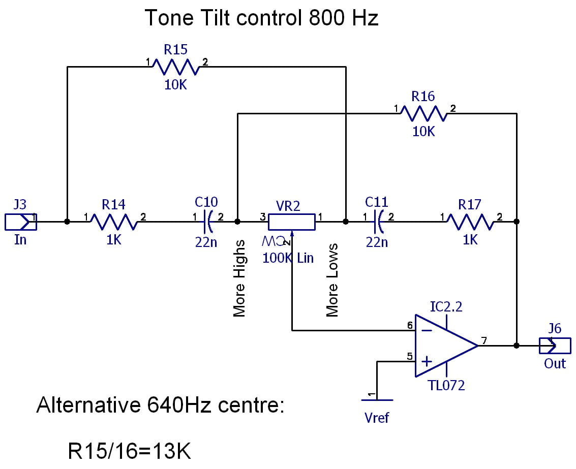
Rod Elliott is rather rude about the circuit, but he’s thinking about it in a hi-fi context. For our sound-sculpting purposes, it might be just the thing.
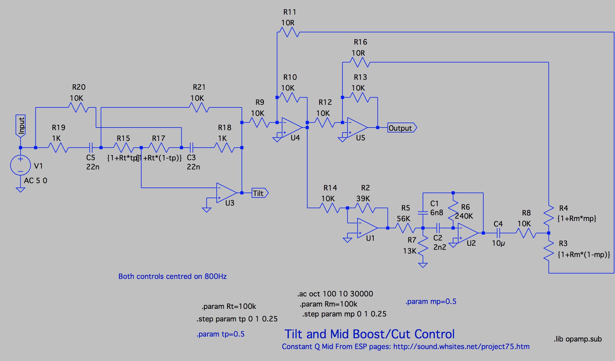
The other part of my two-control scheme was a Mid Cut/Boost. There are lots of ways this could be done. For some reason, initially I decided that a constant-Q design would be a good idea, and again I started with a design from the ESP pages, this time from a graphic equaliser project.
Putting these elements together in an LTspice simulation allowed me to see the resulting frequency responses. The Tilt control as I found it was centred on 800Hz, which is a pretty good starting point, so I left it alone and designed the mid-cut/boost to match. This was a question of finding a good set of component values for the Multiple-feedback bandpass filter that the circuit is based around. I use the extremely useful OKAWA web-based filter design tools for this kind of task. This gave me a Rev.1 schematic:
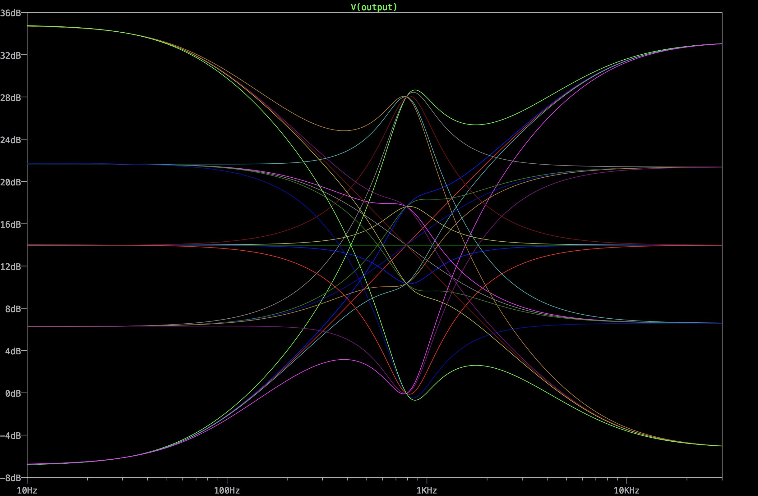
This gave me a working tone controls, but there’s still a lot wrong with it. It’s far too complicated for a start. Five op-amps just for two knobs? That’s pretty wasteful! However, the response graphs I was getting looked good, so I thought I was on the right lines:
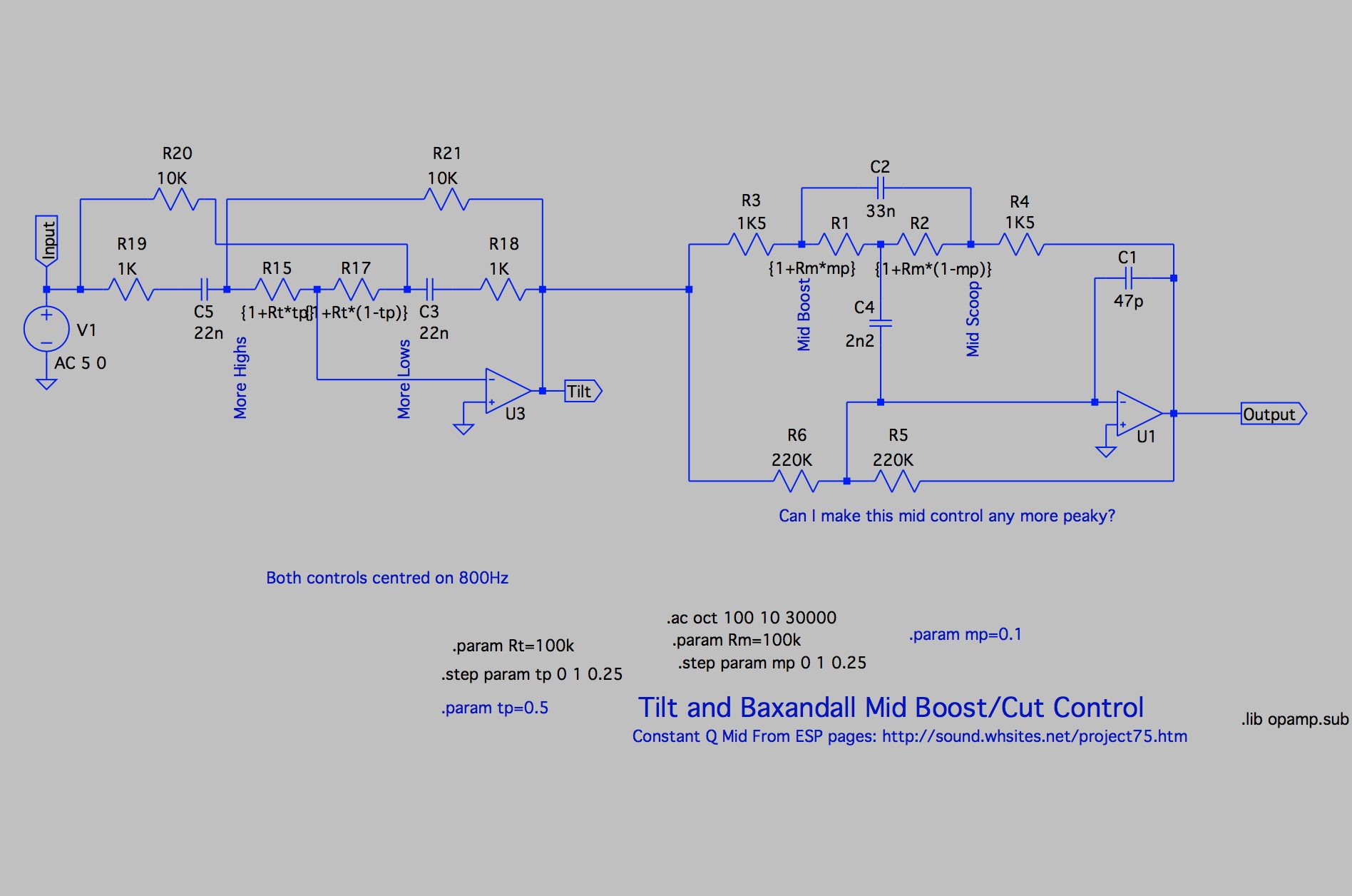
At this point I decided I needed some feedback from my contemporaries, so I posted a thread about the design on DIYStompboxes.com. While I got some positive feedback for the design, it also confirmed my suspicion that it was over-complicated, and Scruffie suggested an alternative Baxandall-type Mid control instead. So I went back to the simulation and swapped the constant-Q stage for the much simpler Baxandall style mid control. This is not constant-Q, but perhaps that wasn’t really important. I wasn’t clear in my own mind why I’d made that choice initially, so it wasn’t too hard to let it go. That gave me the following design:
Comparing the frequency response with the previous design shows how similar they are in overall character, even if there are a few differences of detail. Mostly the mids on the Baxandall design aren’t so “peaky” – a lower Q.

Thinking that perhaps I could get a higher Q sound by using an alternative circuit, I also experimented with a gyrator-based circuit, which is another common option for an EQ section. It’s possible to build gyrators with very high Q if required. The circuit is also pretty simple:
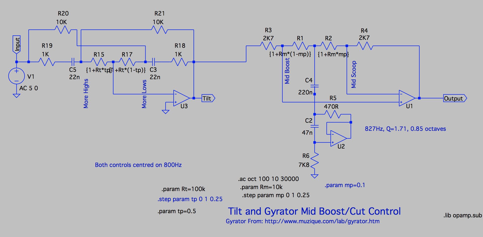
However, looking at the frequency response for this mid control (and this time, just the mid control on its own) showed up a defect.
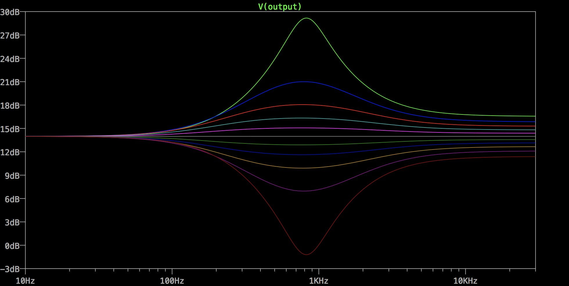
This graph shows the response every 1/10th of the way around the knob’s travel. As you can see, most of the action is at the extremes of the range, with almost half the response between 0-10% for the cut and 90-100% for the boost. The response of the Baxandall circuit was more even and so was the preferred design.
At the end of these initial experiments, I’d tried three different designs of mid control, decided on one that looked to provide the best balance of performance versus complexity, and settled on initial component values based on a crossover frequency of 800Hz. There’s nothing that’s magical about this number, and it could be higher or lower. That is not something that can be decided in a simulation, so it was time to get a circuit together to test it.
What kind of distortion stage?
The basic question with dirt pedals is how “hard” you want to make it. Are you aiming for a soft overdrive that just gives the guitar sound a bit of bluesy grittiness, or are you aiming for something more crunchy? Maybe you want an all-out wall of death noise?! All of those options are possible.
For this design, I wanted a fairly hard distortion, something that would provide plenty of distortion harmonics for the tone control to work with. I hoped we’d be able to get meaty scooped-mid tones and screaming-mid leads, so I wanted something that really rocked, but at the same time I wasn’t aiming for extreme metal, which is a sound of its own.
Like with tone controls, there are various options when it comes to creating distortion, and you need to know which to choose to do the job you want to do. Here’s a few:
- Op-amp with diodes in the feedback loop, Tubescreamer style.
- Op-amp for gain with silicon diodes to ground after the amp, Proco RAT/Boss DS-1/ MXR Distortion+ style.
- Transistors with diodes in the feedback loop, Big Muff PI style.
Of course, there’s a lot of variations here. “Diodes” is a pretty big group, and you have a choice of silicon versus germanium, or LEDs, or power diodes, or transistors of various types wired as diodes, etc etc. Many of these aren’t particularly interesting, but some produce a distinctive sound.
I was aiming for a fairly hard distortion sound, so I chose the second option, an op-amp providing gain with diodes afterwards to hard-clip the signal.
Input buffer with gain
I like to start a pedal circuit with a high impedance input buffer, so that the effect doesn’t load the guitar (the notorious “tone suck”) and so that we have reliable pedal that can cope with whatever you plug into it. If you use op-amps, the typical buffer design is a unity gain voltage follower. This voltage follower design is easily tweaked to add gain, so that’s what I did.
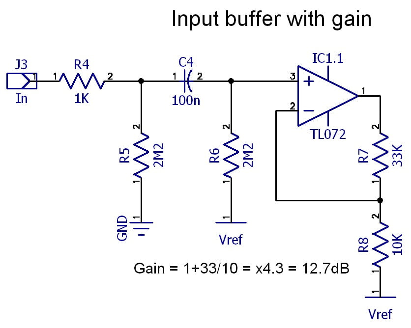
Since this was not the only gain I was going to put in the circuit, there was no need to go crazy, so I picked a couple of conventional values (10K and 33K) and had a look what I got. For the non-inverting op-amp arrangement, that gave a gain of (33/10)+1 = x4.3, +12.7dB. That’s a reasonable boost for starters, and acts as the foundation of our sound. It also gives us a bit more level to work with so that we don’t have to provide massive gain in our distortion stage, which tends to get a bit noisy. If you wanted a bit more boost, swapping the 33K for 47K would be a simple change to make.
The next step was to add a proper variable-gain drive stage to this. With no particular reason not to, I chose another non-inverting op-amp stage. (Note that the +ve input on pin 5 of the opamp is the input from the buffer above)
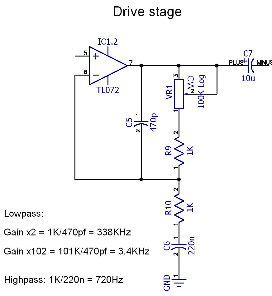
The values here were selected to give a good gain from a easily-available 100K pot. A log pot is chosen because the gain should be linear in decibels. If we aim for a gain of x100, we need 1K resistors. We don’t want the gain to go right down to unity, so we can include a resistor in series with the pot to provide a lower limit to the gain. Given that we already have a gain of x4.3, we should consider that any gain here is multiplied by that factor. On this basis I chose a low value of 1K, which gives a minimum gain of x2 for this stage. With the 100K pot, the maximum gain is (100K+1K / 1K) + 1 = x102. With the gain from the input stage, that gives a total gain of x438.6. That’s +52.8dB, which is plenty of gain.
What’s more tricky than the gain is the frequency response of this stage. C6 acts as a highpass filter and rolls off the bass below its cutoff frequency. In this circuit I chose the TubeScreamer value of 720Hz to avoid muddy bass notes. Similarly C5 rolls off the treble, and interacts with the gain control with more treble being lost at higher gain. Since higher gains tend to produce more distortion and harmonics, this “compensation” effect is quite useful. With the given value, at minimum gain the capacitor has no effect except on ultrasonic frequencies of several hundred kilohertz. As the gain is increasing the cut-off frequency moves down until it reaches 3.4KHz at maximum gain. This is low enough to smooth the op-amp clipping a little at the extreme and to prevent too much treble reaching the next stage.
Signal Clipping
Although we’ve added gain, we haven’t deliberately added any clipping. However, if the pedal runs on 9V, a typical op-amp might only be able to provide an 8Vpp swing before it starts to clip close to the supply rails. At maximum gain, that means that a signal of only 8V / 438.6 = 18mV would be enough to clip the op-amp. Pretty much any guitar can put out 100mVpp, and humbuckers and other hot pickups can produce much more, so this level of gain is enough to produce op-amp clipping already. This means that choice of op-amp in this circuit is significant, since some can “lock up” when driven hard to their rails. We need one that copes reasonably gracefully with being overdriven hard.
After the op-amp, we have the clipping diodes to ground. There are two sets of diodes, one set pointing down, and the other set pointing up, to clip negative and positive peaks of the waveform. Three diodes are used to boost the output level. Diode choice is left open. These could be the typical silicon 1N4148 or 1N914 signal diodes, or they could be germanium diodes like 1N34s, or they could be LEDs of various types. Or different types could be combined for an asymmetrical arrangement, with a silicon diode in one direction and an LED in the other, for example.
Having made these decisions, I now had most of the schematic worked out well enough to be able to lay out a prototype PCB. Here’s the Rev.2 schematic.
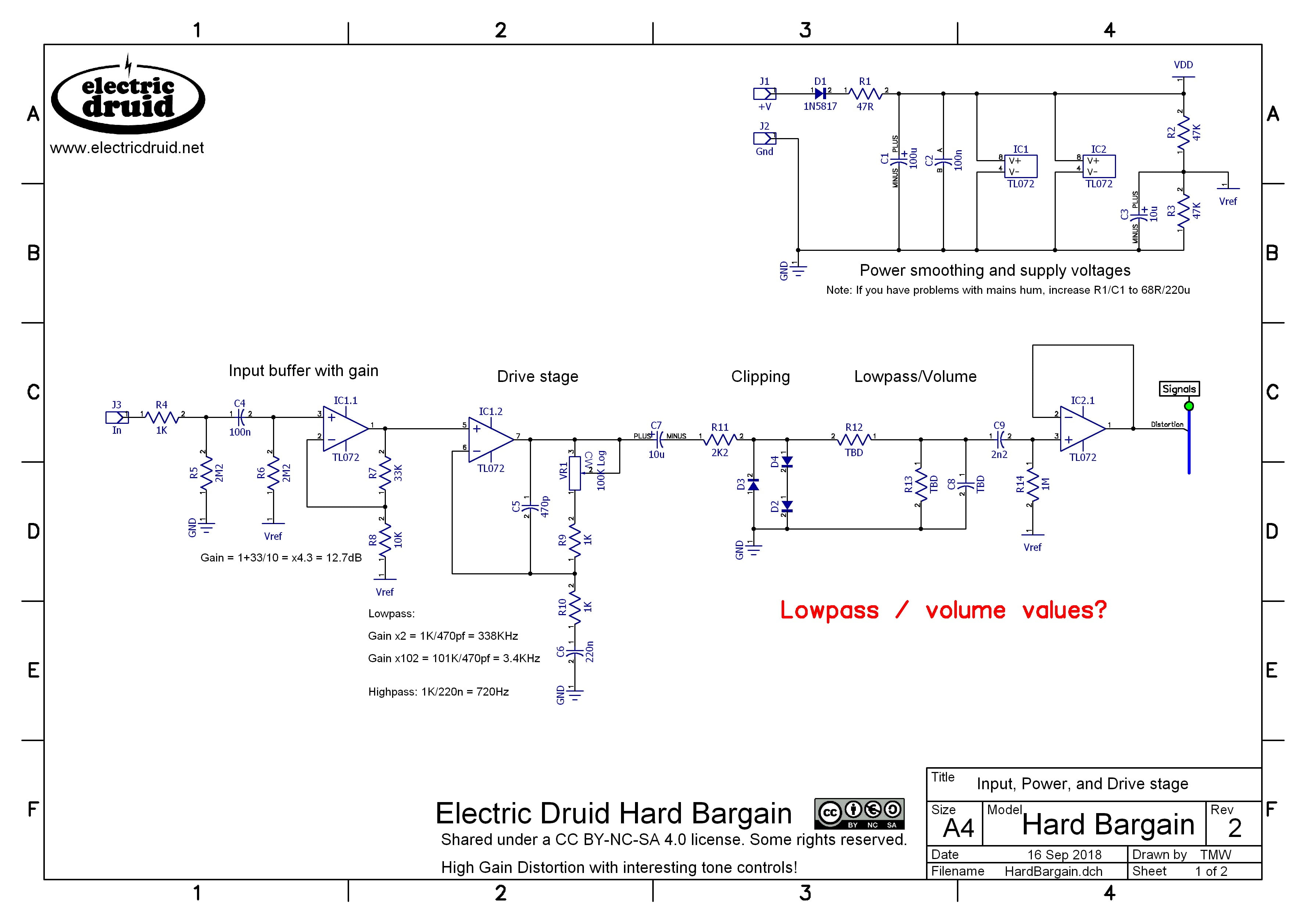
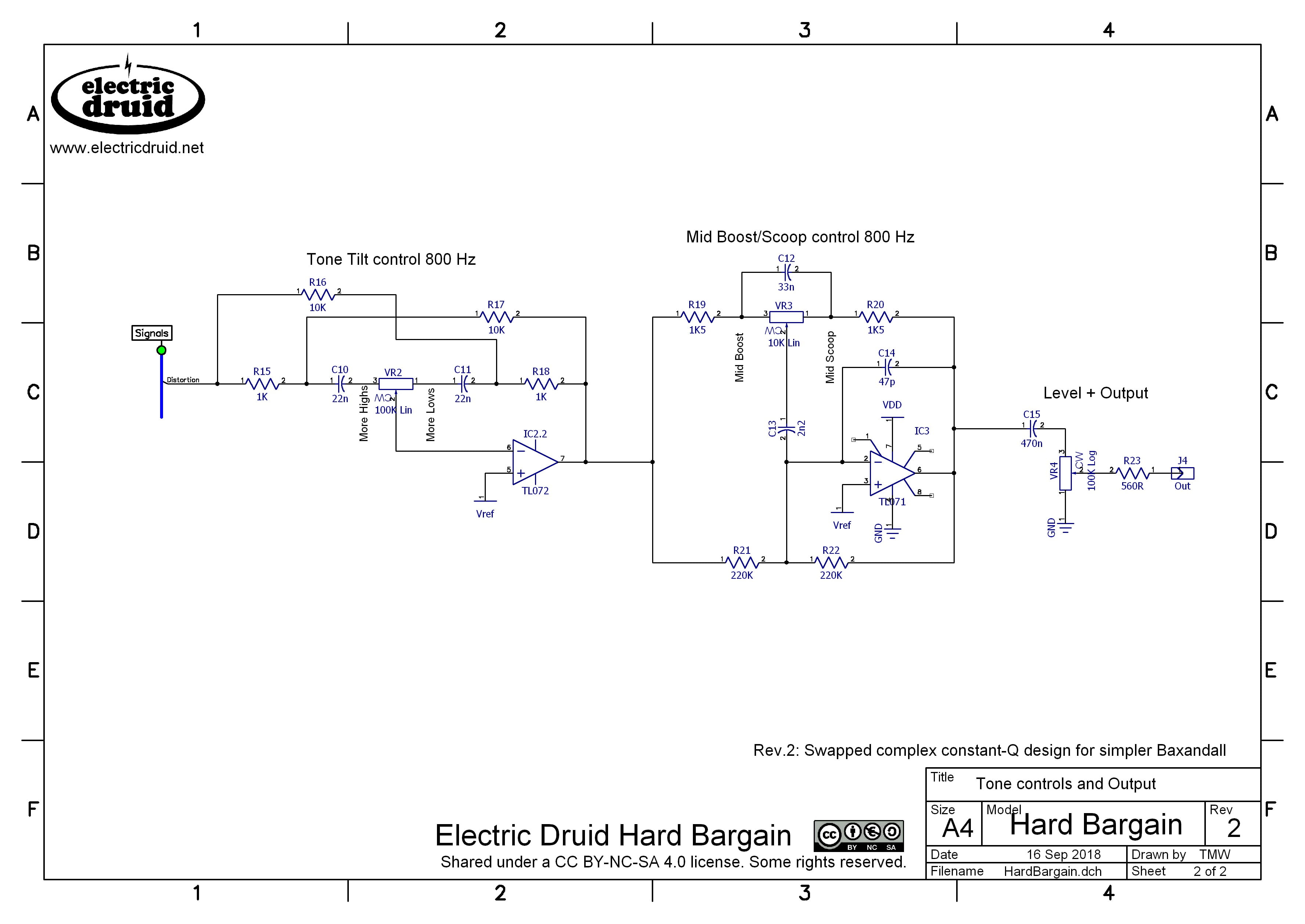
Aside from the parts already mentioned, this schematic includes a potential divider and a capacitor after the clipping (R12,R13,C8) and a buffer IC2.1 to drive the Tilt control circuit. The addition of the resistors and capacitor was to give me an opportunity to remove some treble and reduce the level if required. I didn’t mark any values on these components initially, since I didn’t know if this was necessary, but I wanted space on the PCB to have the option in case it was. The components were marked “TBD” for “To Be Determined”.
The first PCB
The only other addition was to stick a volume control on the end. With the circuit complete, it was time to lay out a PCB so I could hear how it sounded and experiment with some of the component values.
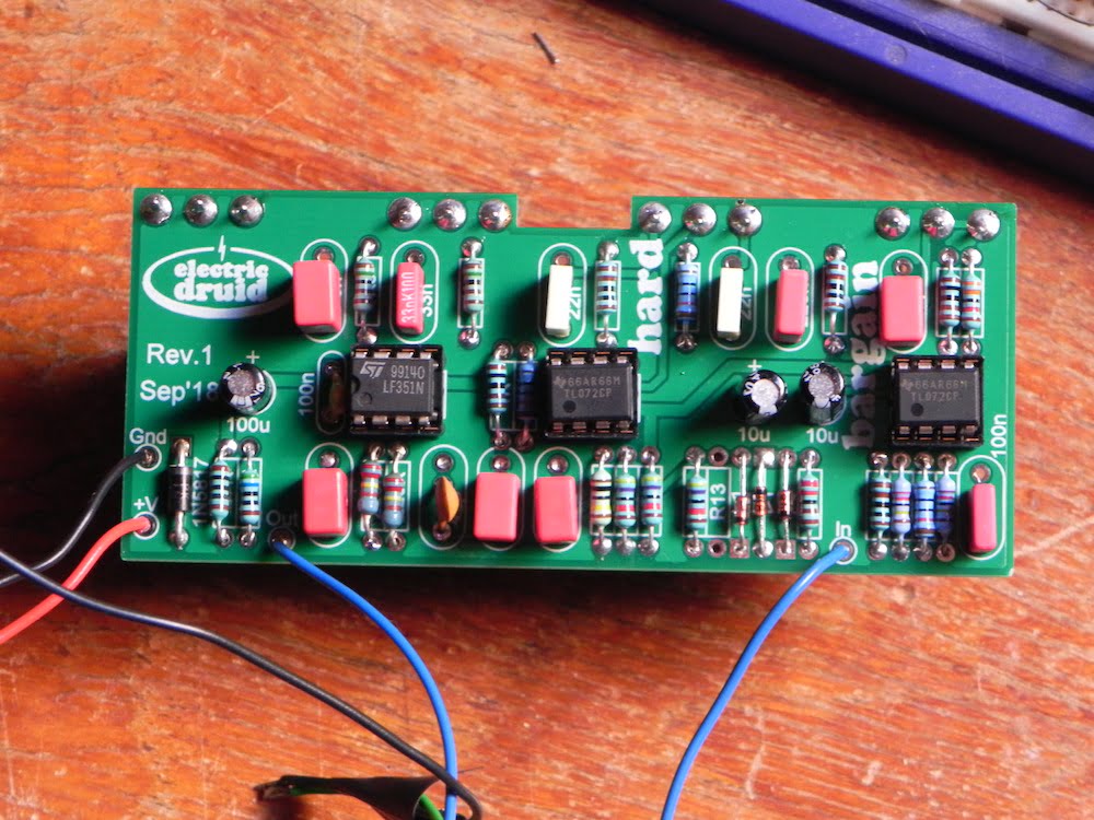
This was the first board I built up. It worked first time, which is always nice. I used 3 x 1N4148 for the clipping diodes. 2 x 1N4148 isn’t loud enough.
The final version, Rev.5
I played a bit with the R12/R13/C8 values and decided that R13 could be left out (loud is good) and that R12/C8 sounded good with a bit of high-end roll-off, and I chose 47K/470p, giving a lowpass action above 7KHz. This just trims a little harshness without losing any high notes or removing too much treble. You can adjust to taste, of course.
The other thing that bothered me about the Rev.2 design was the use of five op-amps. Not only does this offer no significant space saving over using six op-amps (it’s three 8-pin chips either way), but it also necessitates the use of two different chips that look virtually identical. That’s pretty much asking someone to mix them up, and given single op-amps have a quite different pin-out to duals, the possibility of something getting fried is fairly high. So I was thinking that I had an op-amp in hand that I could use in the circuit somewhere. This lead to Rev.3 of the circuit. It was at this point that I spotted an error in the Tilt control circuit. You can play “spot the difference” with the Rev.2 schematic above. So Rev.4 fixed that problem.
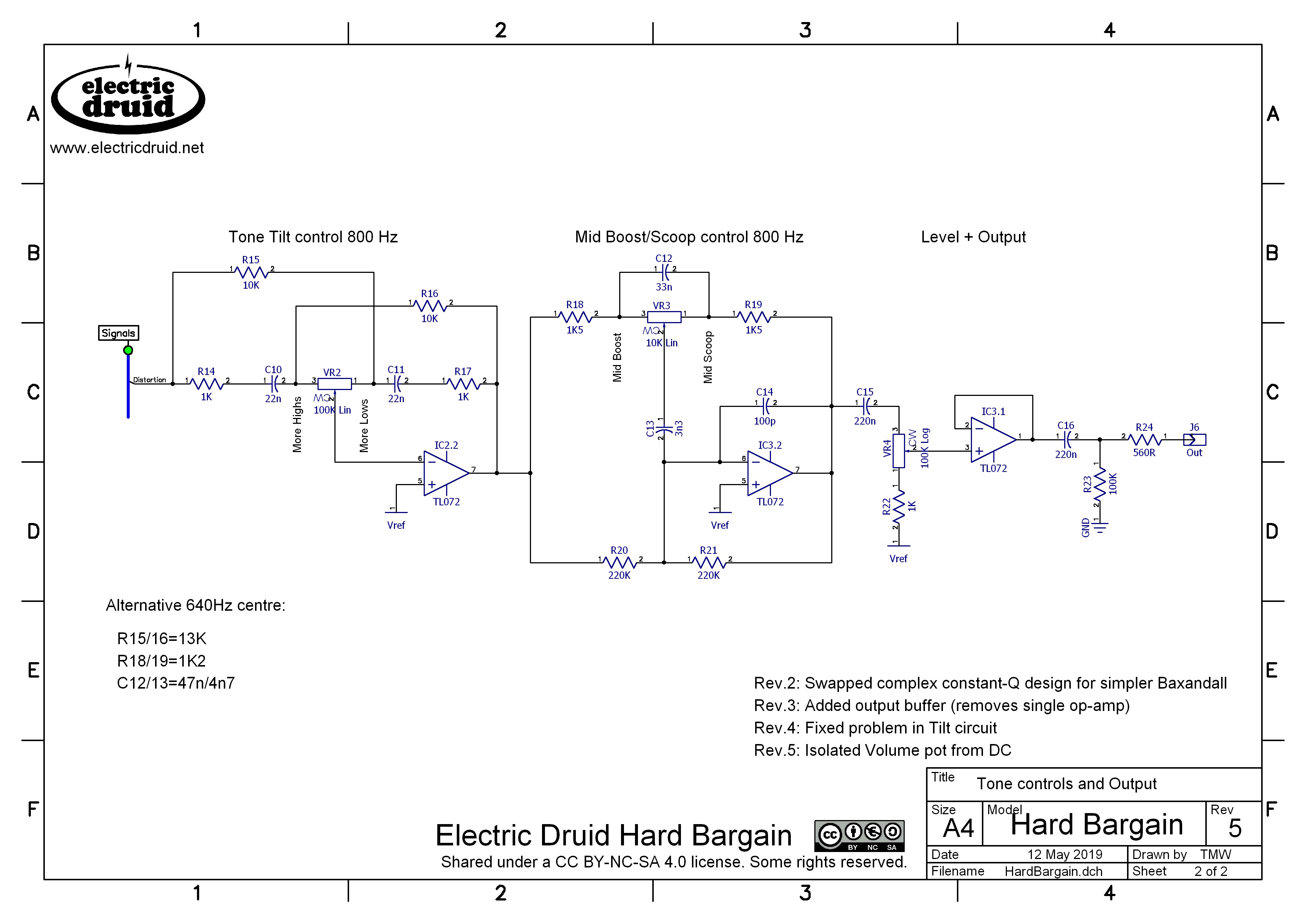
This updated version simply uses the extra op-amp as an output buffer after the volume control. This prevents the volume control from interacting with subsequent circuits and provides a solid, low impedance drive to anything that comes after it. It means the circuit uses three identical chips so you can put them in in any order and it’s all fine. I used TL072, but any common dual audio op-amp is fine, as long as it doesn’t lock up. Rev.5 was a final tweak to add a capacitor between the Mid control and the output buffer to prevent any DC offsets from making the volume pot scratchy. This is the final version.
Can I build one?

Sure, go for your life!
The Hard Bargain PCB finally has all the bugs ironed out, and we’ve got a set of four pots for the project over in the shop too.
The only documents which you’ll really need are the Hard Bargain construction guide and the Hard Bargain distortion pedal drilling template
Project files
If you fancy doing your own layout or PCB, the final Rev.5 schematics are below (and also above!). I haven’t done a Vero layout, but if you do, do please let me know and I’ll post a link to it here.
- Hard Bargain Distortion pedal rev.5 schematic Page1
- Hard Bargain Distortion pedal rev.5 schematic Page2
- Hard Bargain PCB component reference designators
- Hard Bargain PCB component values
Here’s front panel graphics for the two different versions (800Hz and 640Hz), just in case you’re not feeling inspired.
That’s it! This is a simple one, and unusually for me, it doesn’t include *any* digital elements or firmware! Lol!
Comments and feedback
As always, get in touch if you’ve got any comments or feedback about the pedal. We’d love to hear.
Hey Tom, that was a very interesting article to read but most of it is way over my head to be honest, I wish I had the knowledge you have. I am looking forward to these PCB’s being sold as I will most definitely be keen to purchase. Also, I wanted to find out if you are still developing a pcb for the filter fx pedal you were working on a while back? I still have not gotten around to using the stomp LFO chips I purchased some time ago, I have a bad habit of starting too many projects at once. I did build the flangelicious pedal but which I absolutely love.
Thanks,
Shaun.
Glad you liked the article, Shaun. I hope seeing the process helps you understand more about how it works, even if you didn’t get everything.
The FilterFX project is almost done. I’ve tested the Rev.3 PCB and it’s fine. I’m currently doing the documentation and I need to order enough PCBs for the shop, but then it’s ready to go. Should be done in a week or two.
Hard Bargain PCBs will probably be soon after.
Sorry I only just thought to check back on this page and saw your reply now. That’s great news, I will be checking the shop page periodically for the filterFX PCBs to go on sale, I’m really looking forward to building that pedal. Thanks.
Hi Tom,
Will the PCB for the Hard Bargain pedal be available soon – I would be interested in building this unit.
Regards
Hi Gerald,
In truth, it should have been in the shop already, but we had some late problems with it, so it needs another revision. It should be done in a few weeks though. Late May, maybe?
Hi Tom,
Thanks for the update – will keep an eye on the shop for the release.
Regards
Hi Tom, first of all – great article! The only thing that’s missing for me is the information how do you calculate the mid frequency of the Mids boost/cut and how do you calculate the gain of that circuit (I mean – how much boost/cut it has). If you could point me to any resource I’d be grateful – I was searching for baxandall – but it seems to be only bass/treble control and mids have to be added in some other way. I’d be definitely extremely grateful! Regards!
The only place I know that really deals with the equations for it is the 1980 National Audio Radio Handbook, which is flying around the web in PDF format. Definitely worth finding. Not only does it cover the calculations for the Bass and Treble, but also for Mids.
However, that’s not what I did. I just built the circuit in the LTspice simulator, and then tweaked values to get what I wanted. It’s easy to plot frequency responses from the sim (all the graphs in the article are done like that) so you see straight away what you’ve got. This gives you a good understanding of “what each bit does”.
very nice project, and the tilt EQ pairs very nicely with the distortion. on mine, unity volume with a low gain level nearly maxes out the level control where a small movement of the pot makes a large adjustment. One suggestion for future builds might be to use a 100K C taper pot for the volume instead of 100K A taper. Or maybe a 100K B would be the better compromise.
I swapped out the level pot for 100K C and it gives more control over the volume since unity gain is near the maximum rotation.
The balance between the effect and the bypass signal depends on quite a lot of things, including the input level and the tone control settings, so it’s not easy to generalise. Glad to hear you’ve found a way to make it work for you.
Hello,
I just received the Rev 3 PCB, where can I find the schematic for this this revision?
The schematic given above (Rev.5 schematic) is correct.
Hi Tom, I’ve been thinking a lot about building some distortion modules for my (mostly DIY) eurorack and have been reading up on the subject, your write up here has been very informative so thank you for sharing – I just have a question that I’m a bit unsure about before I dive into some building; obviously most designs are geared towards pedals with 0-9V supplies and bias the signal around a Vref of 4.5V, whereas euro systems use -12 to 12V with the signal centered around 0V, so when adapting schematics should my clipping diodes go to ground or to -12V as that’s the lowest voltage? Directly translating 0/4.5/9V designs to -12/0/12V would indicate the latter but I feel like that might not be the correct thing to do. Beyond that, are there any other considerations when designing bipolar distortion circuits or is it pretty straight forward?
It *could* be done either way, but if you’ve got a bipolar supply, it definitely makes most sense to take the clipping diodes to ground. I’d also make sure to use two or three diodes in series (or an LED, maybe) to increase the clipping threshold to account for the larger signal levels in Eurorack gear. Sure, you could clip everything down to +/-0.65V and really get some serious crunch, but you’re losing a lot of headroom, and you’d need make-up gain afterwards which I fear might increase the noise level.
Otherwise, yes, designing this type of op-amp based circuit is alway much simpler when you have a proper bipolar supply and don’t have to mess around with Vref points all over the place. You might find you can drop some AC coupling caps and such like between stages, since the need to keep dealing with a 4.5V DC bias doesn’t exist. Usually the bipolar version of a circuit is simpler/has less parts.
Ah fantastic, thanks for getting back to me. I see, so the peak voltages of the signal are clipped to the sum of the diode forward voltages, I hadn’t actually realised that’s how it worked. So presumably for germanium diodes I’d want quite a few of them in series each way, or perhaps some weird and wonderful combination of germanium, silicon, LEDs etc, should be interesting to mess around with. How would resistors in series with the diodes impact the headroom, if at all? I noticed on inspection that my Frequency Central Volts Platz has a 180R resistor between the clipping LEDs and ground, but wasn’t sure why that was.
Unrelated note: I’ve been trying since this morning to buy a few of your PICs but PayPal just says “Things don’t appear to be working at the moment. Please try again later.” are you aware of any issues with your store or is it likely to be a more general thing on their end?
Yeah, stack up series collections of diodes to increase the forward voltage, and definitely go crazy and try as many different combinations as you can!
A series resistor generally helps soften the approach into clipping – I think I linked to an ESP article above where Rod Elliot discusses this.
Hi, before I purchase a kit from MUSIKDING, I attempted to breadboard your HARD BARGAIN but I need some debugging. One thing I noticed are discrepancies between your installation guide page 3 and the BOM page 6 : the first lists only one 220 nF capacitor, but also a 470 nF, when the BOW lists three 220 nF and no 470 nF.
Where is the bug hidden ?
Also my clipping is strange, and I also lose signal if I set the tilt tone control to the treble side. I am familiar with this tilt control as I already experimented it on tube amps, guided by the excellent book from Merlin BLENCOWE (who BTW also designed a very cool compressor pedal). I have yet to troubleshoot this stage.
I am wondering if the clipping diodes wouldn’t better be referenced to REF voltage, rather than the négative/0V rail ?
The capacitor discrepancy is because I made a late change to separate the volume control from any DC offset so I added C15. Since I then had 2 x 220n, it made sense to change the value of C16 too, to eliminate one extra value and simplify things a little bit. C16 was originally 470n.
It sounds like you’ve definitely still got problems somewhere with the tone tilt stage if the volume is dropping.
The clipping diodes are separated from the rest of the circuit by DC blocking capacitors, so whether the lower end of the diodes goes to Vref or Gnd makes no difference. I experimented on an earlier version with asymmetric clipping, but it didn’t add anything worthwhile in this circuit, so I took it out again (see the notes on the schematic for Rev.3 and Rev.5!).
By the time you wrote a reply, Tom (although you are a super fast replier, particularly on a sunday 15th august), I have found & corrected a wrong wiring on my breadboard, and Ouahhhhh, the thing sure rocks ! And I had realized also that the clipping section is fully decoupled from the rest.
I will immediately order the kit from MUSIKDING and build one, lend it to my fellow guitar players and maybe some will ask me to build more for them.
Just one small regret : that it does not fit a smaller box like a 125B !
Glad to hear you got it working, Christian.
125B? I’ll consider it. Maybe it could be done with 9mm pots or something.
Hi Tom, there are numerous pedals using up to five or six 16mm pots + toggle switches that can be held in a 125B, with top jacks for even less pedal board width occupation. Look at PedalPCB’s photon vibe :
https://www.pedalpcb.com/docs/PhotonVibe.pdf
This is a good example : it even boasts a dual gang pot, and a set of 4 LDR + one filament bulb, and fits well into the 125B. Note that they use 1/8W resistors to save real estate…
Hi Tom, I am very happy to show my rendition f your HARD BARGAIN, that I managed to fit into a 125B enclosure with top jacks : There is just enough room to lodge your PCB.
(except that I ignore how I can upload pictures into this thread…)
Here’s the pictures of Christian’s lovely build of the Hard Bargain in a 125B.
Perhaps I will have a go at redesigning the PCB to make this simple! It looks great.
Hello, I was wondering if anyone could share some feedback on different types of diodes they have used in this build. I’m going to be ordering a kit from Musikding at some stage and I’m torn between the stock diodes and some other options. Just looking for some opinions! Thanks 🙂
Schottky for metal territory (1n5819), germanium and silicon are good too. Als so try 2 diodes –> and 2 <– in parallel for even more distortion and compression. Lots of articles on the net for more info about clipping too. https://www.guitarpedalx.com/news/news/a-brief-hobbyist-primer-on-clipping-diodes
Hi Tom, before I embark on the process of building this, some questions. I want to build this for my eurorack.
1. Does this pair well with synths? Of course this is highly subjective, but what matters to me is that I can dial in from no or little effect, thru a little fattening of the signal, thru distortion, to allout mayhem. I dont like crunch or grit all over the scale.
2. I read somewhere that you said powering it from 12V is no problem. Are there any other modifications necessary? I understand that I have to attenuate the input signal, and that I have to add extra clipping diodes/LEDs. But what about the ouput level? Is it easy to amplify the output to modular Vpp levels? Or does that need an additional amp stage?
Thanks for any tips.
Well, it wasn’t *designed* or intended for Eurorack, so there’s quite a lot of changes you *could* make. The simplest way would be to run the pedal from 12V and 0V as you suggest (no changes needed there) and then scale down the signal going in, and scale it up again going out. The output buffer could be tweaked to provide gain instead (a non-inv amp, like the input buffer) to give the final output boost.
Honestly though, that’s a bit of a waste of headroom. A better solution would be to make more serious modifications to run the whole circuit on the Eurorack standard +/-12V bipolar supply and then add more clipping diodes to increase the clipping headroom. That’d enable you to run the circuit with eurorack levels or something much closer to it and should give you less noise. But it would be almost a new circuit!