
This article is a look at sub-oscillators, a common tactic for fattening up the bottom end, particularly in synths with only one oscillator, or only one oscillator per voice. Classic examples include the Roland Juno 106 and SH101, and the Korg Polysix. More recently, sub-oscs turn up on a lot of modern analog synths since they’re cheap to do and can add more punch and depth. The Arturia MiniBrute, Moog SubPhatty and most of the DSI synths include them.
My synth’s sub-osc only has square waves. Why is that?
A simple square wave one octave below the main oscillator pitch is the commonest sub-oscillator. On many synths, this is the only option, and there’s a simple switch or mixer knob to introduce this signal into the sound. The reason this is commonest is because it’s the cheapest and simplest to do. You just feed the oscillator output to a bistable flip-flop circuit and bingo! Instant sub-osc!
Of course, you don’t have to stop at one octave down. You can repeat the process and get two, three, or more octaves below the main oscillator.
The Roland SH101 has a nice neat implementation using a CMOS 4013 dual bistable chip to offer three sub-oscillator waveforms; square at -1 octave, square at -2 octaves, and 25% pulse at -2 octaves. The pulse is interesting because the 25% pulse wave has the strongest 2nd harmonic of all pulse widths, so there is still a marked -1 octave sound present.
Here’s the circuit from the SH101:
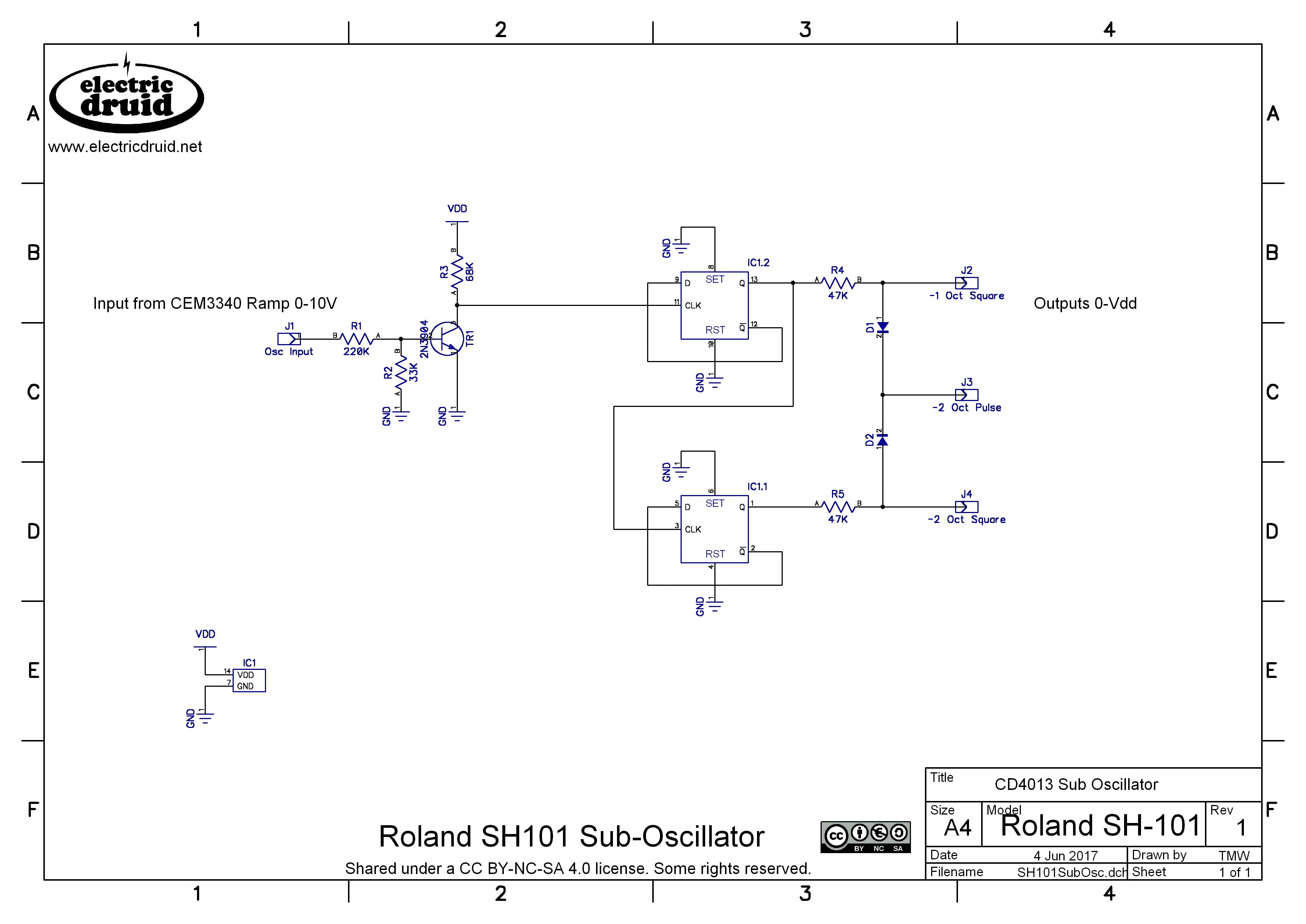
It’s a pretty simple pair of flip-flops, with the 25% pulse being achieved using a couple of diodes as a diode-OR circuit. If either flip-flop output is high, the OR’s output is high. This gives a signal which is high 75% of the time and low 25% of the time – a 25% pulse wave (ok, so it’s a 75% pulse wave really, but it’s the same thing).
Note that the original Vdd in the SH101 was +14V, but CD4013 isn’t fussy and it’ll work pretty much anywhere from +5V to +20V.
Some people have had trouble with this circuit using modern 4013 chips, apparently since they are much faster than older ones and the fast !Q transition can get capacitively coupled back into the CLK input. The solution is to slow it down! Instead of connecting the !Q outputs directly back to the D input, connect them with a 1K resistor, and then add a 100n cap to ground from the D input. This RC filter slows the edges down and makes things act more like a 1980’s 4013! Another solution might be to reduce the value of R3 from 68K to 10K or less. This would help speed up the input, and make it less sensitive to the capacitive coupling. There’s a discussion about it over on Modwiggler.
Thanks to Ben for bringing this to my attention (in the comments below) and finding a solution.
Can we get other sub-oscillator wave shapes like ramps, triangles, and sines?
Other sub-oscillator wave shapes like a sub-osc ramp or a sub-osc triangle are possible, but a little bit more involved. Let’s have a look at some ways to do it.
Sub-oscillator ramp waveform
One way to generate a sub-oscillator ramp wave is to take the main oscillator ramp waveform and the sub-oscillator square wave and add them together. If the balance of the components is trimmed just right, this produces a sub-osc ramp.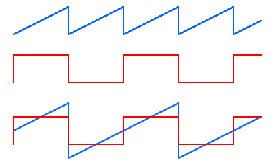
It’s interesting to think about how this works with respect to the harmonic series. The square wave has only the odd harmonics(f, 3f, 5f, 7f, 9f, etc), whereas the ramp waveform has all the harmonics (f, 2f, 3f, 4f, 5f, etc). A ramp at twice the frequency (2f) therefore has harmonics 2f, 4f, 6f, 8f, 10f, etc. If we add that to the square wave at f, we get the complete series – the same as the ramp wave at f. Clever, eh?!
Here’s an implementation of that idea using the SH101 circuit from above to produce the sub-octave square we need. Note that I’ve also added buffers and offsets to the outputs to make everything +/-5V output. This requires a clean -5V source (since we don’t want noise in our audio) but I’ve done it the quick’n’dirty way and used the -15V supply rail.

Sub-oscillator triangle waveform
Ok, so how would we make a sub-oscillator triangle wave?
One way is use the sub-octave square wave to switch back and forth between the main oscillator’s ramp wave, and an inverted copy of that ramp wave.

The top two lines shown the ramp and the inverted ramp, both in blue. The third line is the sub-octave square wave switching signal. The fourth line is what we get if we select the first ramp when the square is high, and the second (inverted) ramp when the square is low.
Since the Ramp’s reset time is not zero (it should be small, but it won’t be zero) you tend to get small glitches on the peaks of the Triangle, as shown on the bottom line. These can be filtered quite effectively, since they’re brief pulses and consist mostly of high frequencies.
Another way to achieve the same effect is to start with a bipolar sub-octave ramp wave like we’ve seen above, and use a precision full-wave rectifier to rectify it. The rectifier “folds the lower half of the waveform over” and leaves it at the top. It looks like this:
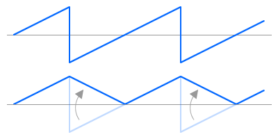 This produces the same results and has similar issues with glitches, especially at the peak of the triangle, but it only requires two op-amps, which is nice and simple.

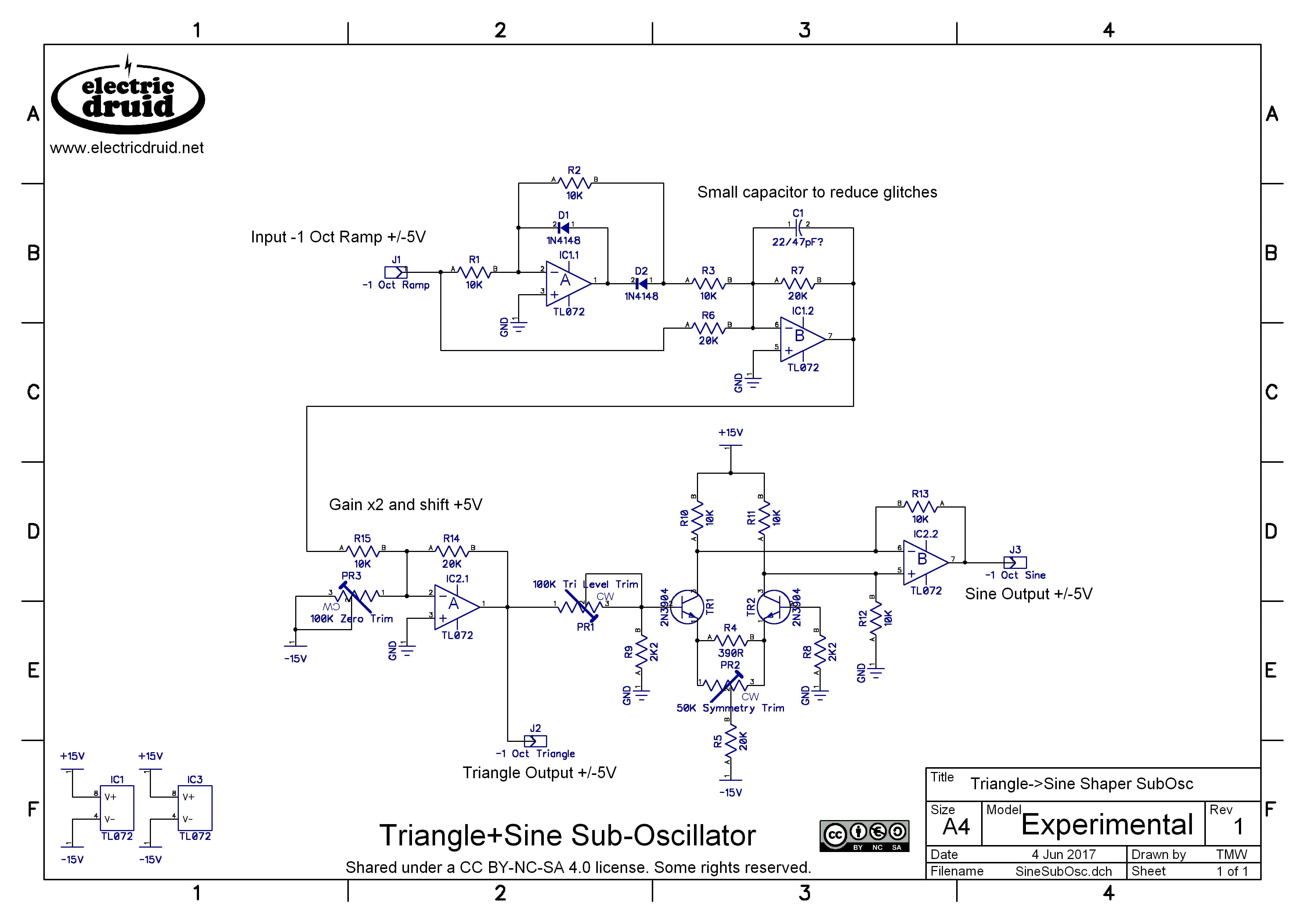
Sub-oscillator sine waveform
The typical way to make sine waves in a synthesiser oscillator is by waveshaping a triangle wave. If the triangle is fed into a distortion circuit with a soft-clipping characteristic, the pointy peaks of the triangle are squashed and rounded, and the result is pretty close to a sine wave. Getting within a few percent error is relatively easy, and with careful trimming, it can be adjusted to within one percent error. That’s not pure enough for test equipment, but it’s good enough for rock’n’roll.
The necessary soft-clipping can be generated by an OTA or by a discrete differential pair transistor arrangement. Tim Stinchcombe has an excellent discussion of the various methods available over on his website. The differential pair is probably the commonest method since it is simple and cheap. Thomas Henry deserves the credit for popularising this design, although it predates his implementation by some many years.
Conclusion
We’ve seen how to produce sub-octave square waves, pulses, ramps, triangles, and sines. Of course, these circuits can be combined and mixed and matched however you like. You can combine a sub-octave ramp generator with a comparator to give you a sub-octave pulse with pulse width modulation, for example. You could do the same with a sub-octave triangle too. There are lots of options, and the limit is really only the amount of circuitry you’re willing to consider as “reasonable”. It wouldn’t be too hard to combine the Square+Pulse+Ramp circuit with the Triangle+Sine circuit to build a sub-oscillator with a full set of waveforms (Ramp, Square/pulse, triangle and sine) at -1 or -2 octaves. While it wouldn’t be hard, it would use a lot of parts, and this is mostly why you typically see simpler designs in commercial synth circuits.
Hi Tom, I love your articles and I find myself re-reading them every now and again. I just wanted to quickly ask: do you know of any commercial synth that produces a sub-osc ramp waveform?
Thanks. I can’t think of a synth that uses a ramp sub-octave immediately, but the Rhodes Chroma used a similar trick to produce its “double ramp” waveform – it was actually a ramp added to a PWM wave, giving the effect of two detuned ramps.
The ARP explorer I has ramp sub-octaves, it goes down to 3 octaves, each one can be switched on and off.
Very interesting! Reading the service manual for the Explorer 1, it seems that they did that by summing a 1′ ramp wave with a 2′, 4′ and 8′ square wave to produce ramps at all three footages (2′, 4′ and 8′). This is the same trick as I’ve explained above, but extended down two more octaves. It’s quite simple and elegant!
Hello Tom , thanks for this article. I am using MU and am hoping to get really slow cycles for modulation . Like one cycle per 10 minutes , ideally with pulse width control for the square wave. The LFO s in MU format that can do that are unheard of.
Is there likely to be any problem with using a comparator and a divider to to generate really slow cycles up to 10 minutes per cycle for example. The designs I have seen seem to be orientated around sub oscillation for audio level or at best for trigger sequencers etc.
Thanking you , Michael
There shouldn’t be any trouble using most of these wave shapers with an LFO that slow. Designing the LFO core itself is going to be where you have more trouble – for analog LFOs, capacitor leakage is going to be an issue, since you’ll need to integrate a voltage over a very long period. Not impossible, but more difficult than the typical LFO. Really really slow stuff like that is another area where digital LFOs score highly.
Interesting article. I’d been wondering why so many suboscillators are square waves and found this post upon googling.
I use a sine lfo tuned one octave down of my main oscillator to get a clean, thick bottom end on my Moog Grandmother. I thought this would qualify as a suboscillator but after reading your article I realize they’re not just separate, independent oscillators that are tuned down.
Cheers!
hello Tom, breadboarding the sh101 sub, I get a lot of glitches. How I can get rid of that?
Cheers!
Sam
Not sure. You need to make sure the flip flop is cleanly clocked, so check the ramp level going in, and check the transistor is switching properly. Aside from that, there isn’t much to it, so I don’t see what else could go wrong.
Thank you again for this article. Just as I asked in one of your other posts about sub oscillators, I see you already had an article about it. I was going to ask if one was to make the full sub-oscillator with all the waveforms, can one use SMT components, and also use a quad op-amp for all the operations without risking too much noise. Thank you.
Hi, thx for your designs! What modifications would these circuits need to accept +/- 5 volts waveforms at it’s input?
Most of them are already set up for +/-5V waveforms. The SH101 sub oscillator is shown with a 0-10V ramp as the input, as that’s what it uses in the original synth, but it should work with a +/-5V input too. It’d be a good idea to add a diode (1N4148 or similar) from ground to the junction of R1/R2 to protect the transistor junction from negative voltages, but otherwise it should work as-is.
I recently built out the SH-101 Sub-Octave. I was using +/-5V pulse from an MOTM 300 VCO.
Once I added the diode (note: the band goes at the junction of R1 & R2 i.e. GND–>}–o–R2). I had to change R2’s value. The transistor was not gating properly. I chose 56K (Tom perhaps you could calculate the exact value). I figured since the +5V peak was half of the 0-10V range, the dividing resister should be about twice what it was in the 0-10V scenario. In any case the 56K resistor worked (perhaps 68K would have been better).
One question I have is “does the diode voltage drop make the peak voltage lower at the junction of R1&R2?” in this scenario (I think not, but IDK).
Thanks for the feedback, O.Z.
The R1/R2 values are both pretty large. To be honest, I’d probably have reduced R1 rather than increase R2. I’ve used similar circuits with just a 10K input resistor, and tested that with inputs up to 20V, so the 220K seems like massive overkill.
The protection diode doesn’t reduce the voltage because it should be reverse-biased at the point at which it matters. It’ll only conduct when the input is negative, in which case we need it to provide a path for the current which is *not* through the transistor.
Thanks for this nice article. I’ve seen similar circuits in which the DC component of the output is removed via an output capacitor; what’s the rationale for the more complicated op amp approach?
A output capacitor is a perfectly valid way to do it. If you go that route, you have to make sure the following stage is properly biased, since you’ve got no DC path from one stage to the next. Note that for sub oscillators the output caps will likely need to be quite large since we’re talking about serious bass frequencies. But there’s no real problem with using electrolytic caps as long as you think about which way around they need to go (which end is biased higher than the other?). I suppose they might thump a bit at switch on, since everything has to charge up to the working levels, which takes a noticeable time for large caps. That would depend on the situation.
The example circuits above are exactly that – example circuits, not necessarily something you’d use in exactly the form presented. For the Square+Ramp+Pulse circuit, I added typical modular synth output buffers to each output. If you were using in a voice circuit, that would likely be unnecessary, and you could either cancel the offset somehow else or simply block it with a cap as you suggest. Ultimately it depends on the situation and intended purpose.
You might have noticed a US company (I have no association with BTW) sell a mod board for the ARP Odyssey. It uses a 4013. Thanks for explaining the background. I’m keen to try to mod my white face using the info you have shared. Many thanks, Craig
Hello Tom
There is a whole family of sub-octave dividers which might be worth a mention – voltage-controlled dividers. There’s almost enough for a part 2. Modulating the sub-octave by an LFO, envelope or sequencer can produce all sorts of interesting and fun bass burbling and animation.
Most of these work by turning pulses (usually) from the square-wave into a (useful) staircase wave, comparing the CV with the staircase and resetting it, so it resets after a number of pulses.
Three examples of this are:
– Serge – Divide by N Comparator (uses a counter and a simple 5 bit resistor DAC to produce the staircase – also good as a clock divider for sequencers)
– CGS48 VCO (very simple limited-range circuit, but will also produce odd intervals like a 5th below)
– Jurgen Haible JH3 VC divide-by-N
http://jhaible.com/legacy/tonline_stuff/hjvcdbyn.gif
Another one worth a mention is the Maplin Harmony Generator
(http://www.muzines.co.uk/articles/harmony-generator/3574)
which is capable of producing octaves above and below the fundamental – uses a PLL.
Steve
Hi Tom, Sam and anyone else having trouble with the Roland SH101 circuit. Apparently there is an issue with the newer ICs. The ‘improvements’ that TI have made mean that some of these older circuits don’t do what it says on the tin. I built the Roland circuit to use mainly as a clock divider but couldn’t get the -1 octave output to work at all and was getting weirdness out of the -2 octave output. Then I came across this thread
https://modwiggler.com/forum/viewtopic.php?t=221841
The fix for me (clock divider, we’ll see how it goes at audio rates) was to add a 1K resistor between D and Q! and a 100n cap from D to ground. There’s more information in the thread I linked to above.
Thanks Ben, that’s interesting. I tried it on the breadboard, but I used an old 4013 that I’ve had in my drawer since forever, so I didn’t see this problem.
I can now also confirm that the mod to the Roland circuit that I describe doesn’t affect how it works as a sub-oscillator.
To be clear. I’m replacing the wire from D to Q! with a 1k resistor and adding the cap to ground, but only on the first divider stage with the -1 octave output. The second stage looks after itself, (not sure why).