
There are a number of situations where it is useful to be able to crossfade between two different signals with a single control. Examples might be a wet/dry control on a delay effect, or a waveform knob on an oscillator that goes from ramp to square continuously.
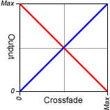
The simple and obvious way to do this is with a dual-gang pot. Each gang controls one signal, and it’s easy to wire so that as one increases in level, the other decreases, as shown in the graph.
But can it be done with a normal single-gang pot? Well, yes, it can.
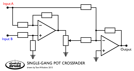
This circuit idea shows how. A differential op-amp has its inverting input fed from Input A, whilst its non-inverting input is fed from Input B. The output from the diff amp is Input B plus an inverted copy of Input A. With the Pot grounded, the output mixer only sees the direct signal from Input A. With the pot at the top, the direct signal from Input A is cancelled by the inverted copy coming from the diff amp, and all that you get is the non-inverted Input B. In-between these two extremes, you get a linear crossfade from one input to the other.
We can use this same concept to build a single VCA crossfader too. In fact, the single VCA version comes out simpler, since the VCA can fufill the roles of both the differential amp and the pot, and the I-to-V stage that often follows a VCA can be used as the final mixer.
Shown below is an experimental voltage-controlled Big Muff Pi tone control that I developed. The Big Muff’s tone control is essentially a passive cross-fade between a lowpass filter and a highpass filter. The circuit isn’t perfect, since the two inputs have different impedances, and the impedances are low enough to interfere with the passive filter networks, but there’s a ton of interactions in the original anyway, and this circuit works well enough as-is.
If you remove the lowpass RC and highpass RC and feed the two inputs from different signals instead, what you’ve got is a voltage-controlled single-VCA crossfader. Cool, eh?!
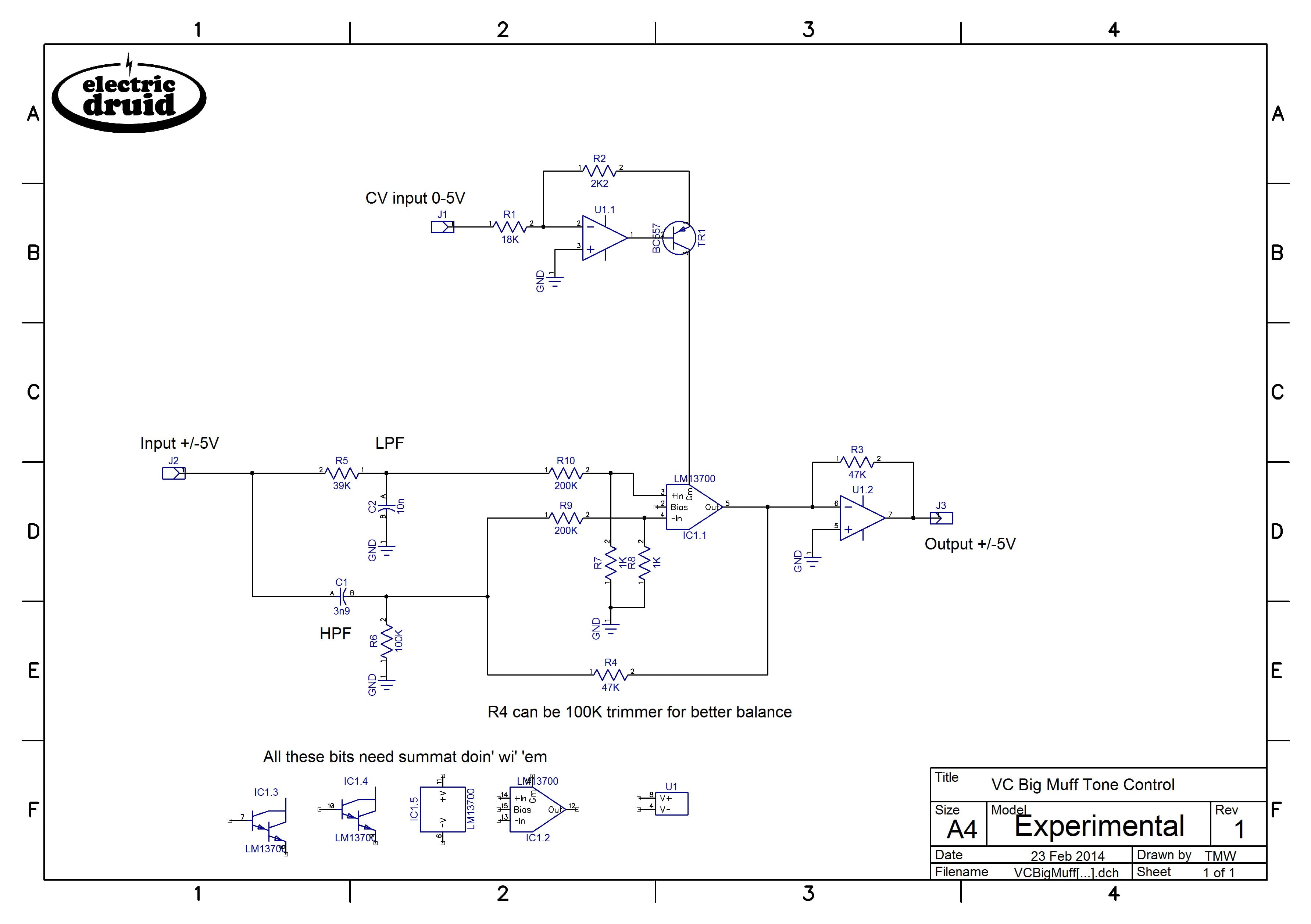
I built this using half a 13700 VCA, but it’d work equally well with the (extremely similar) CA3080 single VCA. Or you could use both halves of the 13700 and build a crossfader for stereo signals.
when looking on your Expierimental V1-Schematic, i have following questions:
instead of LPF & HPF i could use a Audio-Jack and have 2 Inputs (instead of crossfading between LPF-HPF)?
the 0-5V CV is this liniar? meens 2,5V is middle (booth Signals equal Gain?) or is it logaritmic… i ask because i will use a DAC to controll it.
thx mike
Hi Michael,
Yes, absolutely, you can drop the LP and HP filters and crossfade between two audio inputs. The VCA CV is linear. Controlling it with a DAC shouldn’t be too difficult. Let me know how you get on!
Hi,
thanks a lot for your work!
I just put the circuit together on a breadboard. It seems to me, that it is not linear more logarithmic. I have to say, i did a change to the circuit: I tryed a 2n3906 and an BC558 instead of the BC557. maybe thats the problem.
The controll current for the LM13700 seems to be exponential. Wich should be canceled out by the logarithmic response of the LM13700 VCA (as the datasheet says).
Any ideas?
Lorenz
Edit: the current ist NOT exponential( just testet it ( current goes linear from 0uA to 416uA at 5V), so the VCA should have a logarithmical response!
No, the 13700 has a linear response to control current. OTAs in general do. It’s true that a lot of VCAs are exponential.
“Or you could use both halves of the 13700 and build a crossfader for stereo signals.”
This is exactly what I will be doing!
Quick question:
What is U1 in the schematic?
U1 can be any audio op-amp. I used a dual package. TL072 would probably be the “standard”. You could also use LF353 or a 1458. There are plenty of other more audiophile options too, with prices to match!
HTH,
Tom
the schematic looks very interesting. I am looking for a simple single pot (fader!) crossfader. Am I correct than the value of the pot or fader doesn’t matter too much (it goes linearly between the two extreme case, so any value should do that).
And would input A not be inverted (if the pot goes to ground)?
The value of the pot isn’t critical, but you need to think about it in relation to the value of the resistors. The input impedance of the inverting op-amp will load the pot down if the resistors are of a similar or smaller value than the pot. A good general rule of thumb is that the input resistor should be 10 x the pot value, so with 100K resistors used throughout, you’d use a 10K pot. That way the response of the pot stays genuinely linear.
Since the final output mixer is inverting, the output is inverted with respect to *both* inputs, not just input A. Add another op-amp to compensate if that’s a problem. Often this circuit snippet is part of a larger circuit and you can arrange to get one extra inversion elsewhere in the circuit, or sometimes it simply doesn’t matter (mixing oscillator waveforms in a synth, for example).
HTH,
Tom
thanks a lot! I will give it a try!
Hello tom
Were you able to get the top circuit working? I built it with all equal value resistors, and the signal in the “B” input never fully cancels out. It is always at 25$ blend regardless of the pot setting. Any ideas?
-Sig
You say it’s always at 25% regardless of pot setting? That’s not right. With the pot at the bottom, the Input B signal should be grounded, and there shouldn’t be any way it can get to the output. Try only feeding it one signal and makes sure you get the result you expect for each channel, and then try both again. Something is definitely fishy!
HTH,
Tom
Is there a similar simple circuit for paning?
Input A can be faded (CV) to output B or C?
Good question! I don’t know of one, but it might be possible to do a similar thing for panning.
Hi Tom
I built the circuit and its work great (as crossfader)
but i have some issues
1. As “Sigfreed” mentioned above: the input “B” is never get to 100% always i got little from the input “A”, i changed the feedback resistor to 100k trim and its got much better (around 31K) but its never make full crossfaded to B signal, there is any way to get it work properly make 100% A with 0 volts and 100% with 5 volts??
2. the output is decreased by -8db than the input signal.
3. I’m also tries to use it as “Volume control” and Connected “A” input to Ground, again ther’s no completely silent when the pot is Fully in CCW posiiton (0V), so i removed R4 (feedback resistor) and the 200K input resistor, so the ground connected directly to the LM input.
Its worked good but still have the -8db decreased issue, so i tried to feed it with 15V CV , and the gain raised back to correct volume, but when i crossed the ~12.5V I’m getting “pop/click” noise (and its happen just before getting the pot to full CW, around 3 o’clock position),
I saw the answer you written above about the 10 times input resitor value, you think its should solve that issue?
Regards
Hi Dekel,
1) This is question of getting the balance right between the two signals. As you’ve noticed, having the feedback resistor as a trimmer helps balance them. I don’t know which way around you have “A” and “B” on the VCA, but perhaps the VCA isn’t shutting off completely.
2) You can adjust the output level by altering R3/47K on the output I-to-V stage.
3) What you’re doing here is converting the circuit back to a VCA. You’d be better off looking for a circuit that’s intended as a VCA to begin with. I haven’t got one here, but this is a good link:
http://srv4.electro-music.com/forum/topic-57995.html
There are also examples in the LM13700 datasheet.
The pop/click comes from offsets at the inputs of the OTA. These can be trimmed out, and for VCA applications you’ll often see a “zero trim” on one of the inputs for exactly this reason.
Good luck!
Tom
I’ve worked with that circuit based on LM13700 for a couple of months. I’ve tried a few different configurations and can confirm the bleed issue.
Let’s say the configuration is (signalA + (signalB – signalA) * otaGain). With 0uA control current, you get 100% signal A, 0% signal B. With ~550uA control current you still get about 5% signalA, 95% signalB. I’ve put a trim pot to precisely tweak the amount of control current and I could get it to “pretty close” but never to cancel 100% of signal A. It gets quieter as you get closer to some magic number around 550mA, but only up to a point, then starts getting louder again. I suspect it might be because of the non-linearities of the OTA (I do use linearising diodes, hooked up to 9V through 10k resistors).
I suspect for 100% cancellation it’s better to use one side of the OTA per signal and 2 control current sources working in reverse.
Yes, for complete cancellation, the two signals need to match very closely. That probably means the circuit isn’t suitable for all purposes. I included it here because I think it’s a neat trick and it can be useful in quite a few situations.
I agree. Super useful circuit!
Just wanted to confirm the issue so people know that it’s within the realm of possibilities to not be able to get it to crossfade all the way in both directions.
Doesn’t this mess up the phase of the signal? The pathway for is non-inverting input A but inverting for input B, so any further mixing with other signals will behave differently depending on how you set the crossfade up wrt what goes to A and B, respectively.
Yes, but it’s only “messed up” if you actually care. Often it doesn’t matter. For example, if you’re crossfading between two VCO outputs, the phase is going to alter anyway.
Hi Tom , will try thi out. just a few questions:
if for instance i will use only one half of this VCA, are the pin 2, 7,8,9,10,12,13,14,15, left floating unconnected? (just for info, i reckon that in that case i should use another component). and in case i will use the 2 halves, only pin 2, 7,8,9,10,15 are left unconnected?
If you’re not using the buffers, it’s generally regarded as a good idea to ground the base (pins 7 and 10). The buffer outputs can be left open. With the unused OTA…I’m honestly not sure. I’ve left them with all pins unconnected and nothing bad happened, so I guess it’s ok, but I don’t know what “best practice” is supposed to be.
I’ve built it into a pedal and it works for the audio signal (thanks!), but I’m having troubles making it work to crossfade CV (slow changing / DC voltages). I am guessing that is because of the OTA clamping the output at supply voltages. But now I’m confused, if that’s the case, how does it work for audio signals?
As far as I understand the “model” for this schematic would be:
((signalA – signalB) * gain + signalB)
And that is exactly how it works for audio signals if I raise them to 4.5V and power the OTA and the OpAmp with 0V, 9V. But.. how? Let’s say signalB = singalA + 0.5V and gain is 1, the OTA output would be ((signalA – singalB) * gain = -0.5V), but the OTA can not go below the supply voltage, so it would give 0V, which would lead to distortion. So it’s not supposed to work.. at least not cleanly, and that’s what I am seeing when I try to plug in CV.
If I try to plug CV values into the crossfader, I’m getting more of this behavior:
clamp(V-, V+, clamp(V-, V+, (signalA – signalB) * gain) + signalB)
Where both the OTA and the mixer would clamp their outputs at supply voltages and therefore I’m not able to make it work.
Am I missing something?
I think what you’re missing is what’s missing from my schematic – details of the power supply!
My little snippet of circuit as posted above was actually used in a Eurorack module (The Frequency Central Meth Amp) so it was running from a +/-12V supply. Like that, it should handle CV inputs of probably +/-8V or so without any problems, and maybe as much as +/-10V, since that’ll be about the level at which the op-amps start to clip. If you run it from a 9V single supply, then you do have more problems. The “ground” now becomes a 4.5V bias, and the -V supply is 0V. Obviously biasing audio signals to 4.5V is pretty simple, since we can just bias the OTA inputs and then connect the audio with capacitors. Since DC will not pass through a capacitor, no such simple option is open to us for CVs. And since the OTA and op-amps will still clip close to the power supply, the range of CV inputs we can handle is limited to something like 2V to 7V.
Hey Tom
Do you think it would possible to drive the CV input from a square wave (and triangle wave too) LFO, and make the crossfader cut/mix from A to B?
Sure, it’s possible. If you can get the CV range right it shouldn’t be too hard. Some people report that this circuit never goes completely to one side since it depends on accurate cancellation to get one signal, so watch out for that.
Hello again.
I’m back here to report on how to behave with the unused half of the OTA. By tying the Bias input pin (1 or 16) to -V instead of GND, that will ensure no current flowing into that half. That also means that nothing can happen.
reporting from EEVblog:
—
I contacted a TI application engineer with this question a while back:
“I need to properly terminate an unused OTA section of an LM13700.
I’m thinking that connecting the amp bias input (pin 1 or 16) to V- (pin 6)
should disable the input. I also plan to leave the buffer inputs open.
Is this a good approach or is there a better way to do this?
Thank you.”
This was the response.
Lee,
That will work well. Pin 1 or 16 can be open, but connection to pin 6 ensures no bias current.
Regards,
Ronald Michallick
Linear Applications
—
Thanks! That question often comes up, so it’s good to have a solid answer!
Hey folks,
I’m just starting to build this, but I’m not that familiar with the LM13700. Is the GM pin show in the schematic pin 1?
Also, pin2 bias, is that just not connected?
All help gratefully received.
Jon
Yes, Gm/Iabc is pin 1 (or pin 16 for the other OTA). Pin 2 bias isn’t used here and is left unconnected.
I very much appreciate your articles, store, and site, and endless help, so thank you immensely. My question is would this be suitable to possibly rig up a harmonic tremolo, honestly not too different from the tone controls you have shown here? My k owledge on them is limited at best yet but seems Iike that’s kinda the thing they do, modulate the two signals out of phase with each other , like the highs and lows? I do note you said that both input signals are inverted at the output in respect to the Input phases, so one would still need flipped again, but otherwise does this seem reasonable? And my apologies for kinda going out of the bounds of what this article is about to begin with. Thanks again
Yes, a harmonic tremolo would be quite a nice use of this circuit. The example circuit with the BMP tone controls is almost it, if you can live with single pole filters. Some harmonic trems do use single pole filters, but some use two-pole filters, from what I’ve seen – I don’t know what the original amps did exactly. The circuit was intended for a Eurorack module, so it assumes a +/-12V supply. Running it on a 9V single supply might need a few tweaks. But otherwise, add an LFO and off you go.
For anyone still interested in this circuit, I was able to mostly solve the bleeding issue. The key was dividing down the input signals much more, then boosting the signal again in the output stage.
Here’s a falstad simulation: https://tinyurl.com/ys23z7zf
With a TL074 and one half of the LM13700, you get a full VC crossfader with good accuracy, that doubles as a VCA with one input unplugged.