
What’s a “compander”? It’s a simple way to make your circuit quieter! So how does it work? Let’s say we’ve got a fairly noisy effect, like a BBD. The basic idea is that you make quiet signals louder before you put them through the effect, and then you make them quiet again after the effect, and thereby make the noise quieter too. And that’s the clever bit!
“Compander” is a compound of “Compressor” and “Expander”, since those are the two parts of that process. The compressor is the part that makes quiet signals louder (“compresses the dynamic range” in the jargon) and then the expander reverses the process and makes them quiet again (expands the dynamic range). Obviously it’s important that the two stages cancel each other out if we want the overall dynamics of the signal not to get mangled.
 The SA571 chip provides two sets of the building blocks you need to build compressors and expanders, so you can build a companding circuit with just one chip. The two halves of the chip are identical copies of each other (apart from the power pins on pin 4 and pin 13, obviously) so you can use either half for either job.

The C1 and C7 1μF values are a compromise between fast response and low ripple. If you want a faster response, try 470nF. If you want less ripple, try 2.2μF.
The technique is used in the PT-80 delay to reduce the noise added by the PT2399 delay chip. You can see on the PT-80 schematic the two halves of the SA571, one before the delay and the other after. The circuit values have been tweaked a little compared to my example above, but it’s otherwise identical.
It’s useful in any BBD-based circuit to help reduce noise from the BBD. The process will help reduce both noise from the BBD itself, and also clock feedthrough. This can make for a quieter flanger, chorus, or analog delay. The compressor stage goes in front of the BBD pre-filter (the anti-aliasing filter), and the expander stage goes after the BBD post-filter (the reconstruction/clock filter). The diagram below shows the layout of a typical BBD-based pedal. This could be a delay, or it could be (with the optional LFO) a chorus or a flanger. They only differ in detail, not in structure.
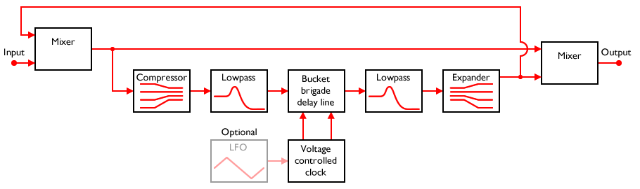
This diagram makes it quite clear why good quality analog delays or flanger circuits are so complicated! That’s a lot of stages! Still, they’re all there for a reason, and if you want to try and reduce noise, you probably need to add a compander.
What does the ‘faster response and low ripple’ mean?
The compressor/expander stages have to derive a signal representing the overall volume level from the input. This is usually done by rectifying and lowpass filtering the waveform with a fixed filter. If the lowpass filter’s cutoff frequency is too high, some of the original audio will still be present in the volume-level-signal (the “envelope”). This is “ripple”.
If you reduce the cutoff frequency of the filter to remove the ripple, you can easily make the filter so severe that it cannot respond to quick transients and fast note attacks. The envelope response becomes slow. So there is always a trade-off between high cutoff/faster response and low cutoff/less ripple. No single solution fits all situations, and it is best to tweak a design for your intended purpose.
HTH,
Tom
Hi Tom,
what will happen when we change the value of the C6 capacitor?
Regards,
Maks
Probably nothing good! The purpose of C6 is to provide a path to ground for the AC signal. R2+R3 provide DC feedback around the output op-amp, but AC feedback is handled by the path from pin 7 back to pins 2 and 3. That path is AC coupled, so can’t affect the DC feedback.
HTH,
Tom
Hi Tom,
Is there a difference between an AGC (Automatic Gain Control) and a Compressor?
Thanks,
Ed
Technically, I don’t know. Practically, no there isn’t much difference. It’s possible that an AGC would reduce peaks as well as boost quiet sounds, whereas a compressor only boosts quiet sounds (at least as far as I understand it). But I’m not certain. Certainly they use very similar techniques and technology, and the differences are only in how it is set up.
Hi Tom,
I’m currently trying to figure out how the Expander side is biased correctly. The PT80 uses a 10k on pin 12, yet in your example it is disconnected. I’ve seen 8k2 been used in the compander cookbook and sometimes up to 20k. What does this resistance do?
The other question is there are some SA571 with 15k/25k internal resistances R3/R4, how can those be biased?
The stages are designed so that you can modify the internal resistance values by using external resistors in series or in parallel with them. In the expander case, it uses the internal resistances, and doesn’t need anything connected to pin 12. Notice pin 11 is connected to the output, to provide feedback around the op-amp.
Firstly, 15k/25k isn’t very different as a ratio from 20k/30k (0.6 vs 0.6667) so it’s not a huge difference. Since you can adjust the R3/R4 values, you can fine-tune it in any case. The R3 value can be increased by adding a resistor in series on pin 6/11, and the R4 can be reduced by adding a resistor in parallel to ground from pin 5/12. That gives a lot of design freedom.
HTH,
Tom
Hi Tom,
The fundamental difference between a compressor and an AGC is that an AGC tries to keep the output level constant – if there is no input the gain rises to maximum until a signal appears then massive distortion until the gain is reduced to the right level as on most mono cassette tape recorders. The AGC will try to turn the background noise up as loud as the maximum signal level!
A compressor adjusts the relative levels of the signal so no input say -80dB is compressed to -40dB, -60db to -30dB (assuming 2:1 compression).
The expander does the exact opposite to the compressor so there is no noticeable difference in the original signal. If the sytem – tape recorder or delay line – has a S/N ratio of 50dB then the expander will expand that noise down to -100dB.
Another way to look at it is that an AGC is a compressor with very high compression levels say 20:1 to 30:1.
Neil.
So could we say that the AGC is compression with a variable ratio? Furthermore, one where the ratio is inversely proportional to the signal level, so low signal = high compression ratio. Would that be a fair summary?
Hi, great article!
I have a question regarding the use of a compander with the PT2399. ThePT2399 is usually going to clip with audible distortion if the signal goes above/near 3Vpp. Isn’t the Compressor (2:1) going to rise the input signal and make the PT2399 clipping even at short delays?
Thanks!
You’d have to make sure that the maximum level the compressor puts out is within the maximum level the PT2399 can accept, or you’ll get distortion, that’s true.
But the point is really to bring the quiet signals up louder, not to increase the level of the already-loud signals. That’s why it *reduces* the dynamic range – because everything comes out loud, not because everything comes out louder. It’s a subtle difference, but important!
Yes, I get it, thanks you!
I’ll try with a trimpot just after the compressor (as a voltage divider) to very slightly lower the input level at the PT2399 while rising a bit the gain at the output of the PT2399 to make up for intial lowering. It seems that increasing the cap between 9 and 10 of the PT2399 gives greater delay output without changing the overall noise so I may give it a try this way.
I have a question regarding the 10M ohm resistors (R1, R4) which are connected to Pins 1 and 16. What is the purpose for these resistors? Are they needed when using the Coolaudio V571D Compander chip?
The 10M resistors act to limit the gain at very low levels. They’re optional, and you’ll see some 571 compander circuits that don’t include them.
The problem is that the compression causes the gain to go up as the signal level goes down. That means that when there is no signal, the gain is at maximum, which boosts any noise. The 10M resistors help limit the gain in this case and thereby keep the noise level down.
I think the answer to this may be obvious… But I was thinking of using a few of these in between gain stages of a transistor fuzz w eq to quiet the overall final output. I guess my question is, is there any obvious reason I might be overlooking where I couldn’t do that?
I’m not sure I see any benefit in using more than one. You *could* wrap each fuzz stage in a compander, but if you think about what that gives you between two fuzz stages, I think it cancels out. There’d be a expander stage, followed by a compression stage – net result, nothing.
So put the compression in front of the whole lot, boost the quiet signals going in, and then put the expander after the fuzz stages to flatten the noise a bit. Since the fuzz stages will heavily change the dynamics, you might need to control the expander from the same envelope signal that the compressor uses. The Paia Roctave is an example of a pedal that does this:
https://hammer.ampage.org/files/rocktave.pdf
This has two effects – the expander helps flatten some noise, but it also puts back the dynamics that the fuzz removed.
Hi Tom. I have built up a 2399 delay from a schematic/kit on the web. It has pretty noisy repeats and im wondering if a compander is the solution for me. I have tried all the little workarounds i can find, and it doesnt seem to change anything.
https://www.pedalpcb.com/docs/DarkRiftDelay.pdf
this is the one. If i build this circuit, where exactly would i connect it in order to give me the correct result? Is it the same as the PT-80? Many thanks.
Yes, if you wanted to add a compander, the PT-80 circuit would be the obvious one to use as a guideline. The end result of Dark Rift + Compander is going to be a circuit very close to the PT-80 anyway.
Hi Tom, Thanks for this great article.
I have an MXR m169 carbon copy that puts out clean signal only. Tried to replace the compander, but the issue is still present. If I short PIN1 to GND, I have fairly distorted repeats. What is happening?
I recommend posting a debug thread over at DIYStompboxes.com. There’s a post detailling the information people like to see to help you debug something:
https://www.diystompboxes.com/smfforum/index.php?topic=29816.0
The people there are very helpful and knowledgeable, and with a bit of work, it might well get fixed!