
Recently I’ve been working on a four second digital delay with tap tempo and delay trails. There are lots of digital delay projects already, but the vast majority of them are based on the PT2399, which limits both the length of the delay and the sound quality.
A quick summary of the features:
- 0 → 4 Seconds of digital delay
- 12 bit/32KHz input, 16 bit/32KHz output
- Delay trails (tails) on/off
- Clickless effect in/out bypass switching
- Momentary/latching feature on bypass switch for “echo splashes”
- Tap tempo
- Tempo LED to indicate echo rate
- Dry audio path is entirely analog
- Delay Time, Repeats, and Delay Level controls
- High and Low tone filter controls
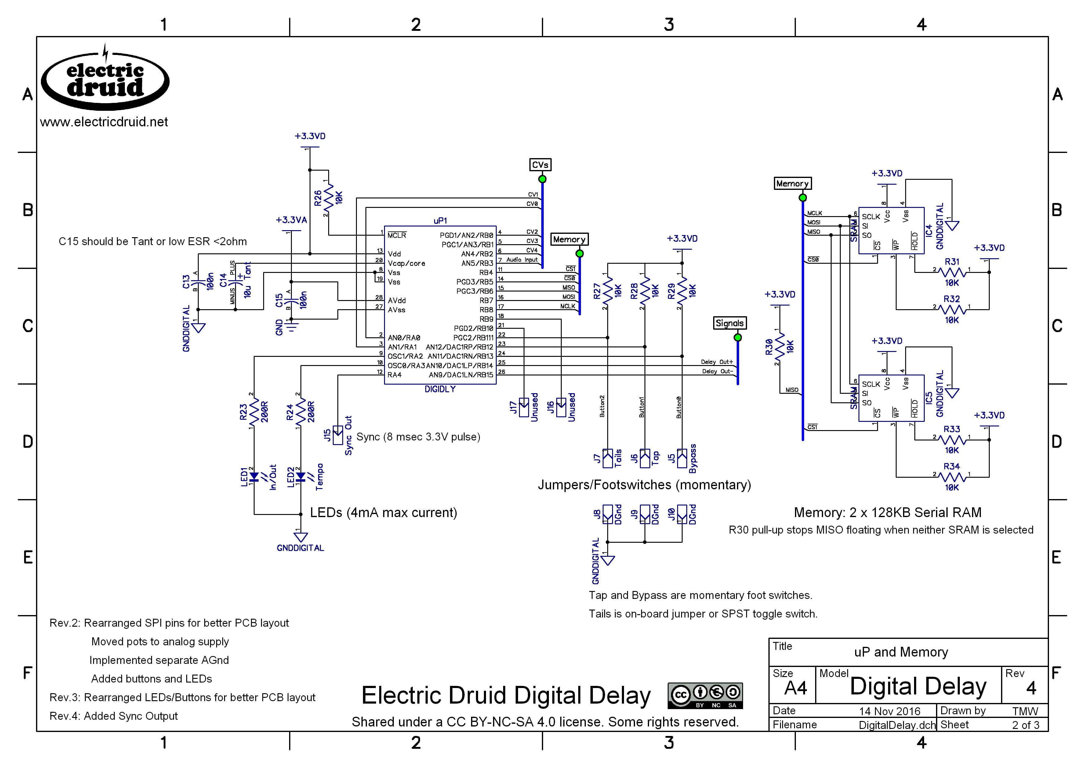
This project is based on the dsPIC 33FJ64GP802 chip, with a couple of 23LC1024 1Mbit/128KB serial RAM chips for the storage. The dsPIC includes a 12-bit ADC and a 16-bit DAC on-chip. The initial sampling is done at 12-bit resolution and 32KHz, but after that, all the internal processing is 16-bit, and the final output is actually 16-bit/32KHz. 12-bit/32KHz is a typical specification for a rackmount studio delay processor of the 1980’s. The sound quality is very good, without being super-clean or sterile. It certainly beats the PT2399 hands down, and it doesn’t suffer from worse and worse quality as the delays get longer either.
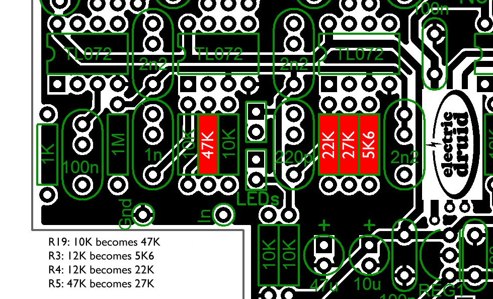
The worst (only) problem is background hiss. The dsPIC’s on-chip DAC seems to produce about 10mV of noise. Some of this is removed by the post-DAC filtering, but about 5mV remains. This is pretty noisy by modern standards. For guitars-level signals, modifying four resistor values improves the S/N ratio significantly. This is described below.
Here’s a video a builder has put on youtube so you can hear it:
(If this is your video and you’d rather I didn’t link to it, please get in touch – thanks!)
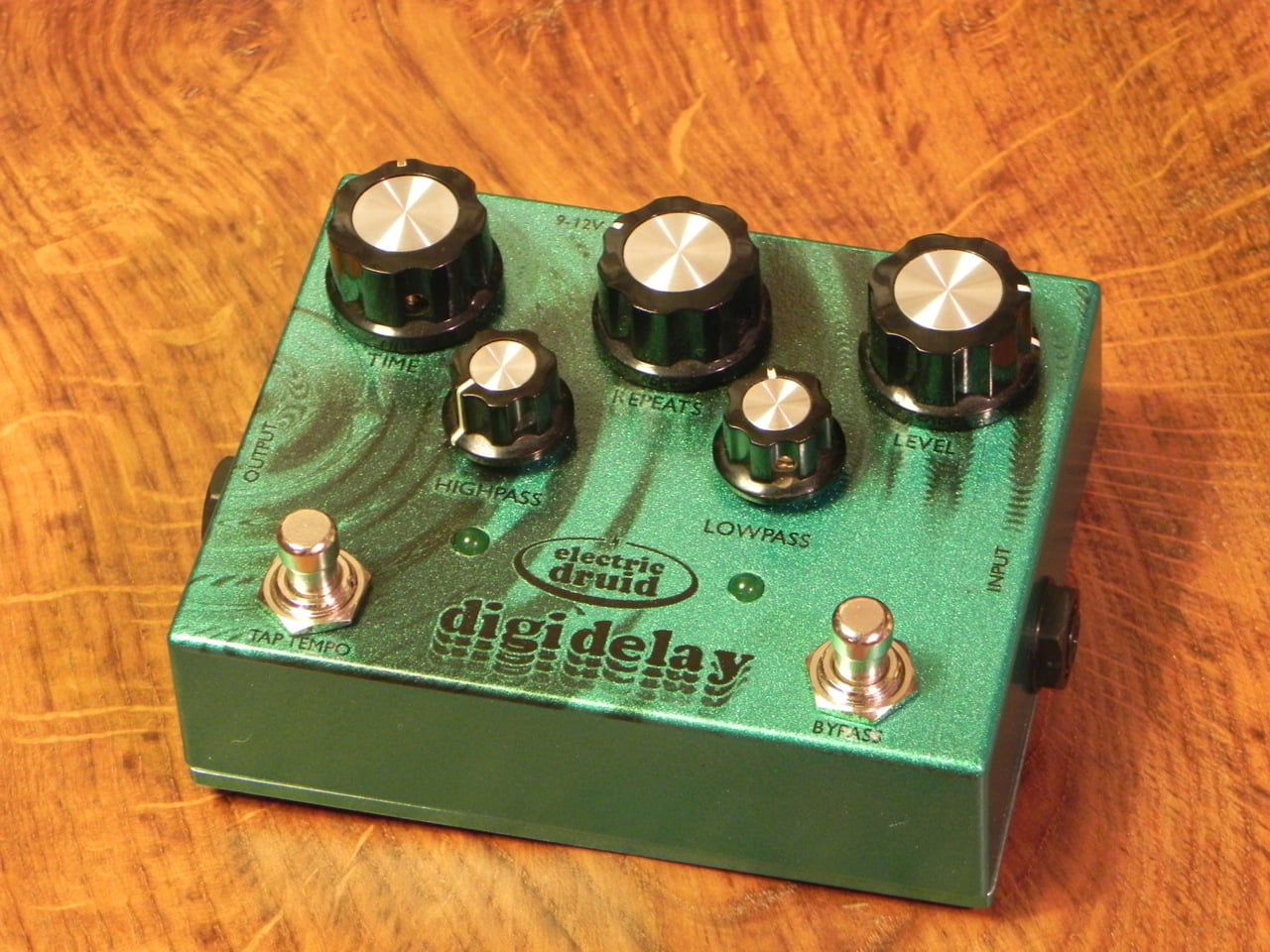
As you can see in the guts photo at the bottom of the page, all the parts are DIY-friendly through-hole DIP ICs. This isn’t easy to achieve for something like this, since virtually all DACs and RAMs are surface-mount these days. I’ve managed to keep it to six ICs, and apart from the 28-pin dsPIC, they’re all little 8-pin DIPs, so the project is able to fit in a reasonably sized enclosure. The PCB is designed for a Hammond 1590BB or equivalent.
The current firmware has five controls. Three are the standard delay controls: Delay time, Repeats, and Delay level. The other two are high and low shelving tone controls for the delay signal, so you can sculpt the sound of the repeats. You can cut the bass on each pass which makes the repeats sound “lighter” and like they’re floating away. Or you can cut the treble, and have the repeats get darker and darker, somewhat more cave-like and subterranean. Or you can do a bit of both, which gives you a band-limited sound on the repeats like someone on the telephone or a cheap radio. It’s pretty versatile.
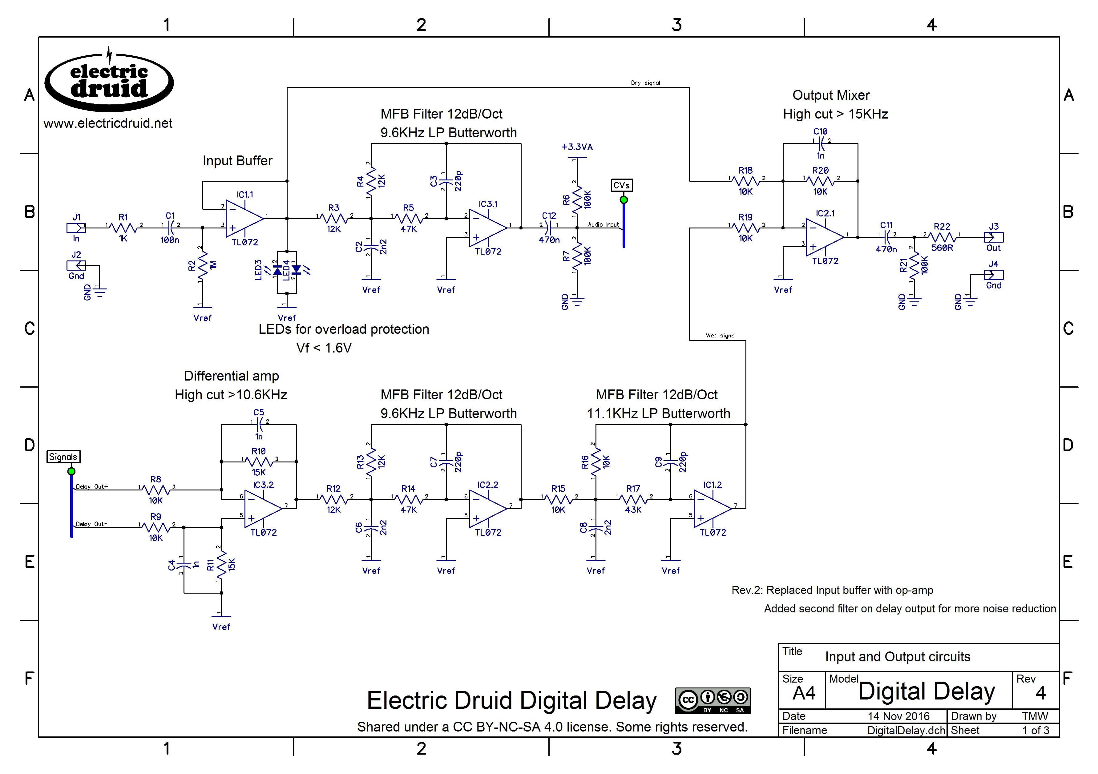
The audio path keeps the dry signal entirely in the analog domain – it is never digitised and comes straight from the input buffer to the output mixer.
I’ve programmed ‘buffered bypass’ rather than add a true bypass footswitch, though this would be possible. The reasoning is that I can do noiseless switching in the firmware by providing a fade-out over a few milliseconds, and I can also offer the option of keeping the delay tails, which is important with so much delay available.
One further addition is the “echo splash” feature, whereby a short press on the bypass footswitch will toggle the effect on or off in the usual way, but a longer press (currently set at “over 0.5 second”) turns the delay on only while the switch is held down, and the delay goes off again when you take your foot off the button. This enables you to add echoes to just a single phrase, and sounds great with the delay trails.
The firmware also offers tap tempo as an alternative way of setting the delay time – just tap the interval you want on the other footswitch. There’s also an LED which flashes at the current delay rate to give you an idea of what’s going on, and there’s a Sync Output to provide a pulse which can synchronise other pedals to the delay rate.
A quick overview of the schematic
The analog side is simple stuff. There’s a buffer, from where the dry path goes off to the final mixer. That’s followed by a anti-aliasing filter, and then the delay line. The delay is followed by a differential op-amp since the DAC outputs a differential signal, and then two reconstruction filters. The final mixer mixes the wet signal back into the dry signal.
The digital side consists of the processor (with its internal ADC and DAC) and the two SRAMs.
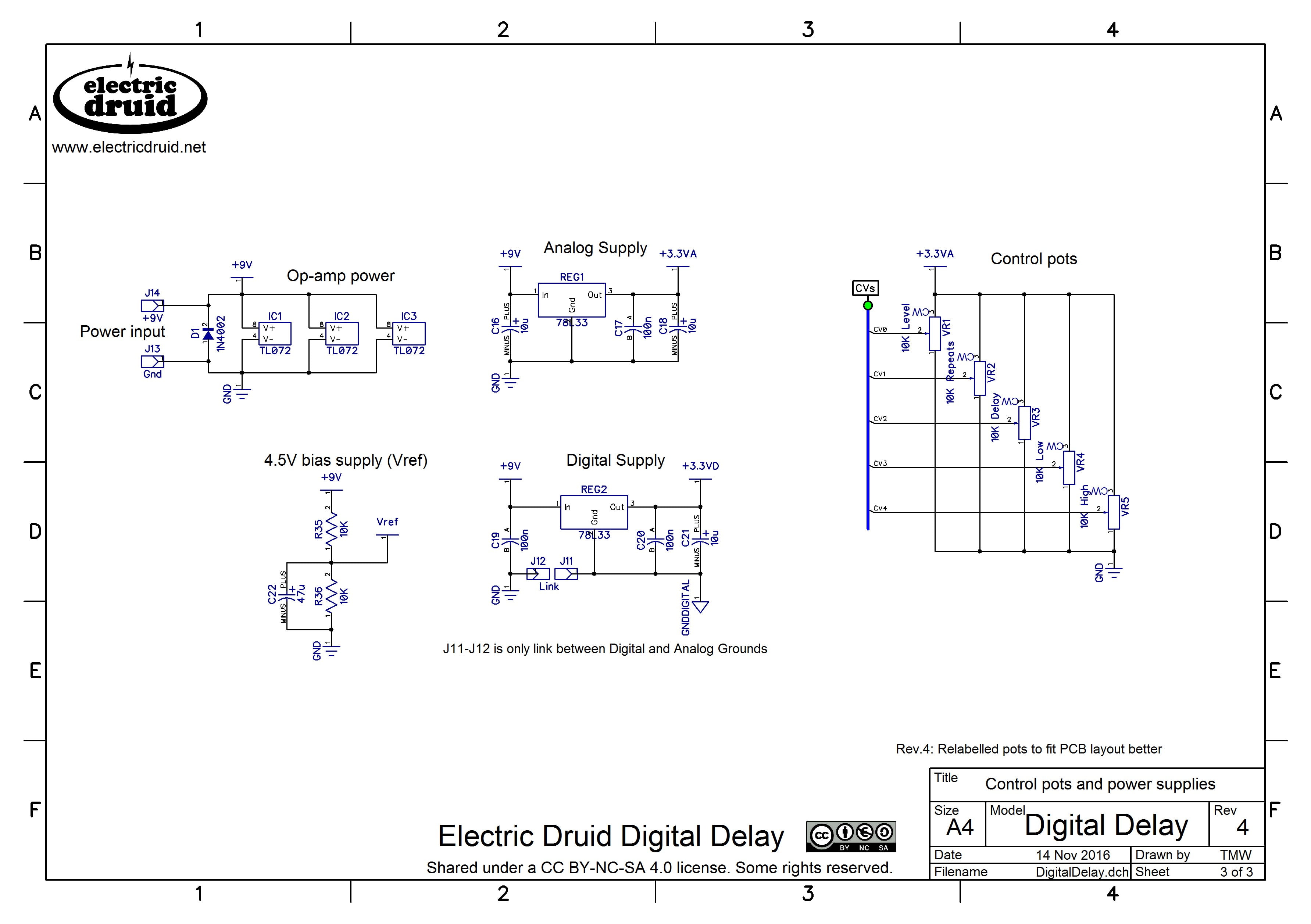
The final parts are the five control pots, and the two supplies. The ADC/DAC use a separate 3.3V supply from the digital side to help keep noise to a minimum. The ground planes are separated on the PCB too.
I’ve used the “diode in parallel with circuit” style of reverse polarity protection rather than the alternative “diode in series with circuit”. The diode in series gives you a hefty voltage drop that I don’t care for. On the other hand, the diode in parallel will short out any power supply which is plugged in in reverse and might blow up the power supply. I regard it as my job to protect my circuit and the job of power supply designers to protect their power supplies from shorts (I mean, that’s pretty basic, right?). Just so you’re warned!
PCBs and chips for this project
Here’s a shot of the Rev.2 PCB in my first unit. It makes for a neat build since most of it is on the PCB. Getting the LEDs the right height requires a little forethought, but none of it is hard. I could have used board-mounted jacks too, but I thought it better to leave people the option of having whatever jacks they like best. I’ve put cutouts left and right for the jacks, and added a cutout on the top edge to make more room for a DC socket. I learned a lesson there from the Flangelicious boards where it’s a tight fit to get a DC socket on the top side of the PCB.
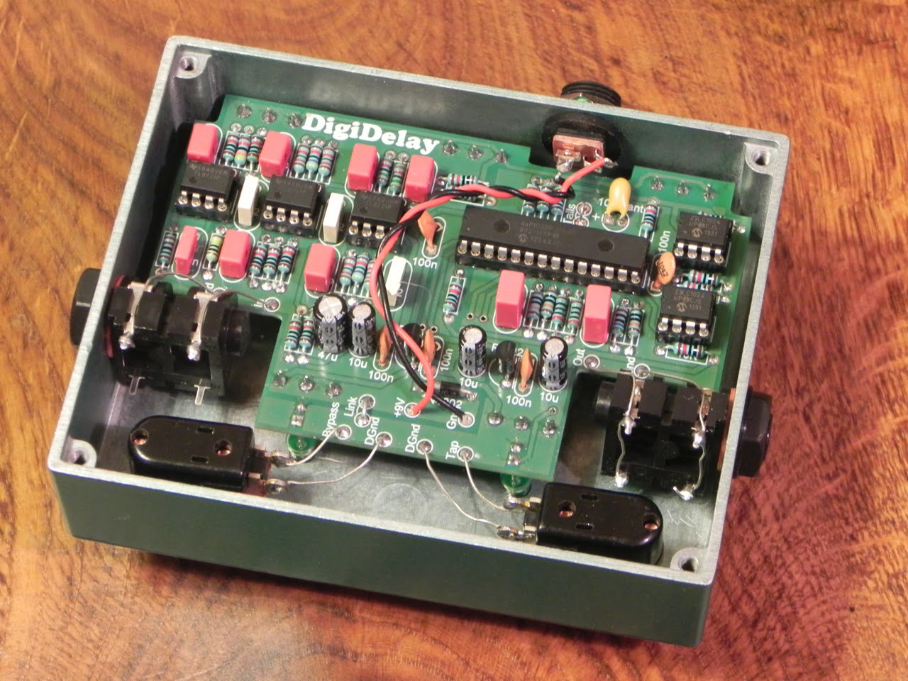
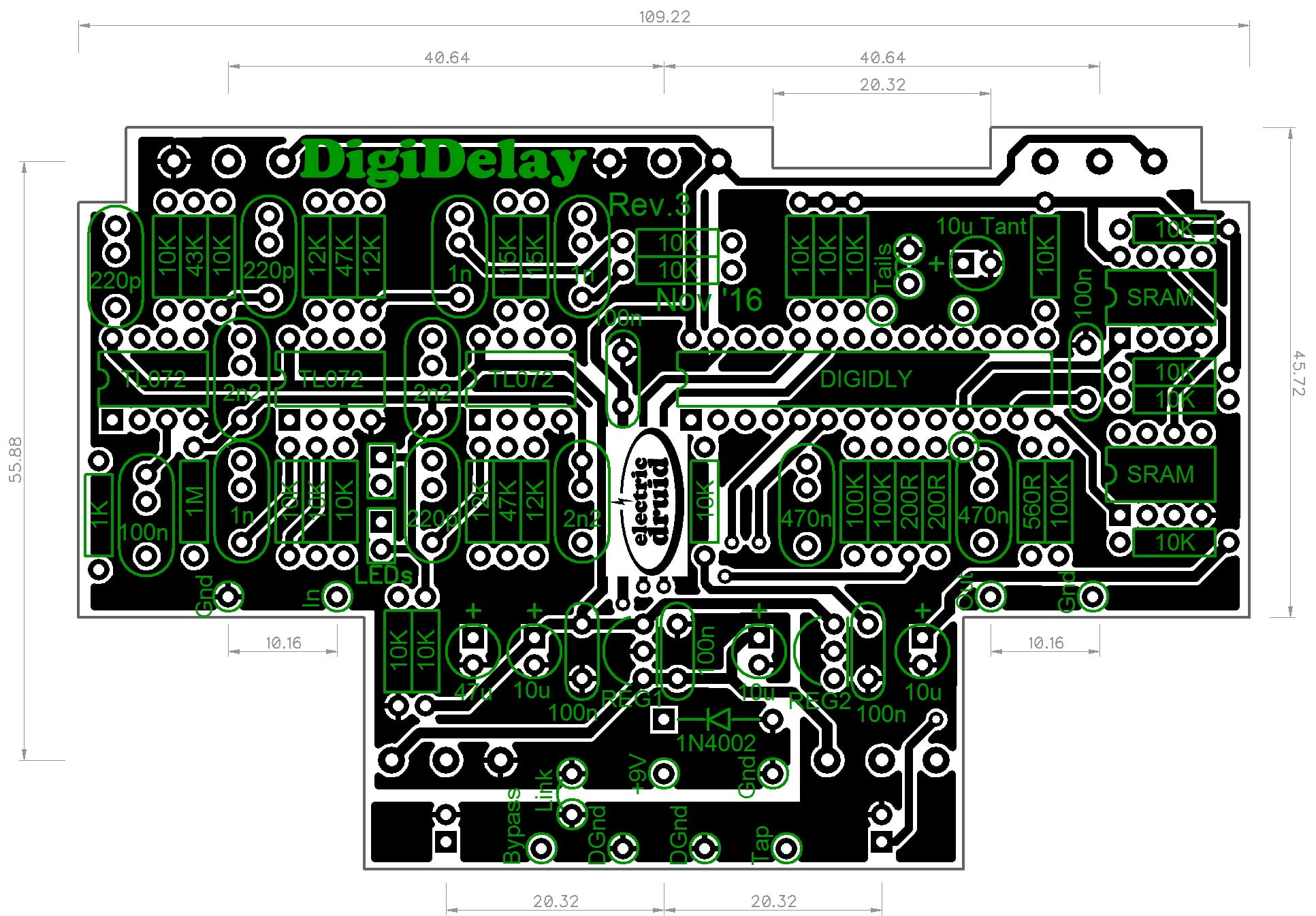
The PCB measures 109x70mm. It is designed to fit into a Hammond 1590BB enclosure in landscape format as above. The PCB-mounted pots make the build easier, and the off-board wiring is very simple.
Ok, so what do I need to build one?

Pop over to the shop and grab the DigiDelay PCB + chipset, which includes the PCB, DIGIDELAY delay processor chip, and the two SRAMs. You might also need a set of pots for the project.
The only documents which you’ll really need are the DigiDelay construction guide. and the DigiDelay enclosure drilling template.
Improving the S/N ratio for low-level guitar signals
There are two main sources of noise in this circuit; 12-bit quantisation noise, and the DAC noise. There’s nothing I can do to fix either of these. They are what they are. All we can do is try and get the best-possible signal-to-noise ratio from the circuit.
As shown in the schematic, the circuit can handle signals up to 3V peak to peak. To get the best noise performance, you need to use as much of this as you can.
If you’re using the circuit with a guitar with a low level output, changing four resistor values can be helpful. These changes boost the signal at the pre-delay filter, and then reduce it again at the output mixer (along with any noise). This gives an improvement in S/N of around 13dB. The maximum input signal level is reduced to 680mVp-p.
Project files
Here are the full details if you want to tweak the code, do your own PCB, or otherwise experiment with it.
DigiDelay DIY 4 Second Delay Project files
- DigiDelay construction guide (Updated to include guitar level mod above)
- DigiDelay enclosure drilling template
- DigiDelay panel graphic for waterside decal (as seen on prototype above) 100%=254DPI
- Rev.4 Schematic (Page 1)
- Rev.4 Schematic (Page 2)
- Rev.4 Schematic (Page 3)
- Rev.3 PCB Reference Designators
- Rev.3 PCB Component Values
Delay Processor and SRAM files
- DigiDelay delay processor chip datasheet
- DigiDelay delay processor dsPIC 33FJ64GP802 assembly code
- DigiDelay delay processor assembled .hex file
- 23LC1024 128KB SRAM datasheet
Going further: A dsPIC-based pedal of your own design?
It’s worth pointing out that the hardware presented here is pretty general purpose. You’ve got audio input/output with a dsPIC to process it and 256KB RAM if you need it. The interface consists of five knobs to control parameters in the code, and two footswitches. That’s a good start for a lot of different digital effects. A change of firmware could turn this into something completely different.

All files relating to DigiDelay by Tom Wiltshire for Electric Druid are licensed under a Creative Commons Attribution-NonCommercial-ShareAlike 4.0 International License. Here’s the legal stuff.
Awesome! Finally a “non-pt2399” digital delay 😉 I am pretty sure this could be combined with the VC/Tap-LFO to get modulated delay time? Can’t wait for the files, thanks again for a great project!
Hey, wait till you’ve heard it before you big it up! But thanks for the positive vibes!
Modulated delay time with the TapLFO would be pretty wild. You’d have a ton of options available then. Since the delay time on this one is a CV input (although 0-3.3V range) it should be doable, although I’ve got some heavy smoothing on the CV inputs on this chip to prevent noise from the ADC finding its way into the audio. So fast modulation might not be an option. I’ll bear it in mind though. Perhaps when it’s all done, I can experiment with backing the filtering off a bit to see how far it can go.
“…with backing the filtering off a bit to see how far it can go.”
Yes, please do that! Because it is no just a freaky idea, but one of the strangest synth effects I know, to s&h-modulate the delay time!
Anyway, hats off to you and I´m in for one (;
Best, Jörn
Oh! This sounds great indeed! With the quality we’re used to from your designs, I’m sure this is going to be awesome! Looking forward to a demo!
Really looking forward to making this project, but I’ve got a few questions about variations I had in mind:
Could I use the StompLFO and a vactrol across the delay time pot to add “chorus” type modulation to the repeats?
Is there anywhere to insert an “effects loop” so that other effects could be applied to only the repeats? This is common in some “boutique” delay pedals, but I’m not sure where to apply the effects in a circuit where the “feedback” path is in the digital realm.
You could certainly try a vactrol across the delay pot to add modulation. It’s unlikely to give anything that sounds like typical chorus though, because the pedal doesn’t change the delay clock to change the delay time – instead it shifts the delay pointer.
The design I’ve presented here uses the Repeats CV input to control the feedback digitally. As such, it’s always inside the chip and there’s no path you could put an effects loop into. However, it doesn’t have to be that way. There’s nothing to stop you setting the Repeats CV to zero to disable the internal feedback, and wiring up an external (analogue) repeats control from the output back to the input.You’d take the delay signal from IC2.1 pin 7 to a pot as a voltage divider to Vref, and the pots wiper to an additional resistor in parallel with R3 and connected to the R3/R4 junction (e.g. using the MFB filter as a mixer). Give it a try and let us now how you get on!
Would “setting repeats to zero” be simply tying to ground, or tying to +3.3VD?
Also… is there a way to change the delay clock with external components? I’m especially interested in getting this thing to “warp”.
Setting repeats to zero would be tying the Repeats CV input to 0V/ground.
You can change the delay however you like by feeding a 0V to 3.3V control voltage to the Delay Time CV input. Make sure the circuit you use for this is limited to this range and, for safety, have a series resistance in line with the CV input – 2K2 or so should be good.
However, the Delay CV is only sampled every 2msecs or so, and changes between one delay time and another are crossfaded slower than this. Experiment with twiddling the Delay knob itself to get an idea of what changes to the Delay CV do before you spend a lot of effort designing something. The current Delay pot simply applies a 0-3.3V CV to the chip’s input, so it is entirely equivalent to an external control voltage (except that perhaps you can’t twiddle the knob as fast you could run an external LFO, but with everything else, that’s the least of your problems). Good luck!
Tom,
Looks very promising! I concur with Robert – at last … beyond PT2399
O.Z.
Great job Tom! Looking forward to this one.
Hi there
I’m interested in the software technique you are using the produce the delay. I wondered if I could ask some questions? The way I imagine it working is to have a sample-write pointer that continually loops around from one end of memory to the other, writing the data sampled at the A/D as it goes? Then a sample-read pointer (which also loops around memory in the same way) is running a fixed distance away from the sample-write pointer? The longer this distance the bigger the delay – meaning sample rate never changes – just the “distance” between the read/write points? Is that how it works? I ask because I’m interested in having a go myself at some of this, though the PIC world is new to me!
Also, any idea how stereo delay effects are produced? How is the stereo effect made? Is it just a fade up/down between the left/right channels?
The way you imagine it is exactly the way I’ve done it. The write pointer cycles through the memory, and the read pointer follows along behind. The further behind it is, the longer the delay.
This method does throw up one or two problems of its own (a variable sampling rate would have different plusses/minuses). For example, how do you change the delay time? If you simply jump the read pointer to the new location, you get an abrupt change in the signal and an audible click. If you twist the ‘delay time’ knob, the repeated clicks become a hideous “zippering” noise. So then you have to think about either speeding the read pointer up with respect to the write pointer to shorten the delay (or slowing it down for a longer delay) or crossfading from the old location to the new. Various different commercial units have used all these methods, and each has advantages and disadvantages. I’m going to try the speeding-up/slowing-down method, because I’d like to have the possibility of modulating the delay time. We’ll see how that goes!
“Stereo” Delay effects can be generated many, many different ways, but mostly they depend on having different delay times for the two channels, which makes the sound apparently “bounce around” between right and left. Have a look at the “algorithm guide” for the old Boss SE-70 for a few ideas:
http://cdn.roland.com/assets/media/pdf/SE-70_PA.pdf
Good luck!
Whether or not these features are a stock part of the design I would love to have a tap input, tap clock output and a multiplier knob for interfacing with other devices.
How is the tap function being handled on this? If it was from the Tap LFO chip that you sell then the features I want would be lying dormant within it waiting to be teased out by whomever wants them. If it`s a little dedicated chip like the flangelicious with all it`s features maxed out already that`s a different story.
Tap input is definitely included – I’ve done that one already. Tap Clock output is not very likely, although I’ve got a Tempo LED output. I’ve been using PWM to make a “flash with decay” on the LED, so it’s not ideal as a clock output. Perhaps it would be better just a simple square wave so that it could also be used as a Clock output too. Pity, because visually it doesn’t look as good. I’ll think about that one.
Multiplier knob is pretty much certainly not going to happen, since I’m out of ADC inputs. But with the tap input, you ought to be able to use a TapLFO to sync it up at pretty much any speed you want.
Ok. I can live without the multiplier.
Im only one person, but I would strongly prefer a square wave for syncing multiple effects, even if the LED blink isnt as good. Then I would be able to multiply up and down the other effects I am syncing (provided they have a multiplier knob of course!)
Any idea yet on what enclosure size it will fit into?
Just a note to say this did make it into the final version. There’s a “Sync Out” pin which provides an 8 msec 3.3V pulse at the delay rate. This can be used to sync other effects, including things based on the TAPLFO chip.
Tom
Does this unit still hum even when powered by a isolated power supply?
It’s not hum, it’s hiss. And it comes from the output DAC, not the power supply, so yes.
What I haven’t tried yet is upgrading the voltage regulators to something lower noise. That might help a bit, maybe.
any way to sync the delay to clock would be amaz balls
any news on the schematic and code? thanks!!!!
Hi,
I got stuck trying to work out how to deal with the delay time modulation, so I’ve been taking a break from it to see if anything occurs to me. What I should do is get what I’ve got so far online though, and let you all have a look. It’s all functional apart from changing the delay time, which is glitchy. I’ll try and make time to get the schematic and current code up.
Thanks a million for your generosity and inspiration!
It seems like a lot of early 8-12 bit delays used companding. Do you think this delay could benefit from that addition (as done in the PT2399 delay you describe)?
On a side note, I put in my vote for delay modulation to produce flange/chorus effects 🙂
Yeah, if you’re concerned about noise, then companding will help. It’s not a perfect process, so it can affect the dynamics somewhat. Perhaps that doesn’t matter too much since it’s only on the echos.
My prototype is quiet, but by no means silent, but I’ve only got 12dB filters before and after the delay, whereas I’ve put 24dB filters in the schematic. That should help keep the noise down further too, since a lot of what I’m hearing is digital hash and would filter out quite well. When I do a PCB I’ll find out.
Your vote for delay modulation is noted. I think what I’m going to do is get Version One out in the world as soon as I get the glitches out of the Delay Time knob. This uses a fixed sample rate and doesn’t include delay time modulation.
After that, I might do an alternative firmware (Version two) using a variable sample rate, which makes delay time modulation a *lot* easier to do, at the cost of lower quality for the longest delays. That may or may not be a significant cost depending on what the final sample rates finish up being. We’ll see when I get there, I guess.
Thanks for the interest, nonetheless.
Tom
Regarding companding, I actually wonder if that added analog circuitry could explain some of the distinctive sound of the early digital delays (i.e., it might be desirable beyond reducing noise). I imagine that analog filtering closer to the audible range could also explain some of the sound. Good luck with a cool project!
Yes, for sure the compounding adds a certain something. Some of the PT2399 delays that are out there manage to get a pretty accurate “analog” sound by using very dark filtering (3KHz isn’t unheard of) and using the original companders. The same tricks would work equally well on this.
Some other things have been shuffled on the list, so I’m hoping to get back to this shortly. Watch this space.
Very cool stuff can’t wait to hear some sounds. I like the idea of 12 bit adc.
Thanks a lot for sharing all these great projects. Because of you i ordered a programmer and hope to use your designs in a diy synth. Althought i am still a noob ?
Not sure but here they are writing about methods to interpolate between samples in delay lines https://ccrma.stanford.edu/~jos/pasp/Delay_Line_Interpolation.html
What kind of interpolation strategy did you implement?
Btw someone metioned clock input for tap tempo. I achieved this with a simple tranny as switch on the tap tempo button. Like this i did my first mod ever, did it on a memory boy deluxe and its realy usefull.
Actually many of the features requested are implement in this delay.. cv controll of feedback would be my suggestion.
Cheers. Tim
Thanks Tim. As an update, I’ve got a Rev.1 PCB designed which goes off for manufacture this week. Once I’ve got those back, I’ll do the final polish on the code and get it all online. Sorry it’s taking so long.
I haven’t used any interpolation, since the delay time is altered by changing the distance between the write pointer and the read pointer in the delay. Interpolation would be required if the delay was modulated, but that’s not going to make it into the first version of the code. I might look at doing a variable-sample-rate version for version two (if I ever get that far) which would then allow delay time modulation without the processor hit of interp.
Tap tempo is included, though. There’s an input for that. And the “Feedback amount” knob is attached to a 0->3.3V CV input, so you could add external CV control of that without too much trouble.
Tom
Edit: I’ve been reading the link you posted about delay interpolation. I did in fact implement the crossfade like they talk about in “Large delay changes”, the last section. If you don’t crossfade, you get a glitch when the delay pointer jumps from one place to another.
Hello
I am very interested for this effect processor.
But I don’t know where to buy this ic.
You tell me address for buying this ic.
And tell me this delay only mono or have a with ping pong delay?
I’ll post a link to the relevant shop page when I get it online. I have to check the prototype PCBs and finalise the code first though. The prototype PCBs should be done in a few weeks, and then I’ll need to polish the code and order production quantities of PCBs and chips. This takes a while, but I want it out there before Christmas.
Thanks for your interest!
Tom
Edit: Sorry, forgot to add – the delay is only mono. There’s no second output for stereo, and no ping pong delays. It would be possible, but the current code doesn’t do it.
Hi Tom thanks a lot for the update. For me it hasn’t be taking long as i just found this project ? i will first have to start learning to program pic.
Cheers
Tim
Hi Tom… nice project you have, and thanks for sharing to the DIY community! I was just wondering if it’s possible to implement program patches so one could recall them, I mean, I can program various delay settings (with all 5 parameters) and store in some internal memory, and pushing a stompswitch I could recall those programs.
Thanks!
Will
Hi Will,
Hey, nice idea. I’ll have a think about it. I have often wondered about programmable pedals. The trouble is working out the interface. Do you have LEDs to show you which program you’re on? or a 7-segment display? Full-on LCD? Can you edit stored settings? How does the position of the knobs relate to the sound you’re hearing? These are the sort of things that make it less straightforward. But there’s nothing insurmountable!
Thanks,
Tom
Hi. Thanks for write back. Yes indeed a programmable pedal suposes more complexity in the interface… but looking as an example my Korg 301-dl delay pedal, it has just 2 delay programs that make it very versatile: with one extra momentary stompswitch and a two-color led, besides the on-off effect stompswitch and status led. With this extra switch one can store the potentiometers status in its two programs so it can be recalled later.
It’s just an idea… 2 delay patches are better than one.
Thanks again, looking forward for your project! Cheers
Will
Yeah, a couple of programs doesn’t seem very complicated to do.
Tom
This seems like this may be a good candidate for a pseudo 16 second digital delay. Ive been trying to come up with a delay that could mimic the functions of the original unit, particularly the “always recording” function of the infinite switch. I’m pretty new when it comes to digital work but would it be possible to be able to infinitely loop one cycle of the delay without filtering (or the ability to add in filtering to emulate infinite filtering of old tape delay units.) Would it then be possible to dd octave/speed doubling or reverse loop type stuff? I’m sorry if these ideas seems way out of the scope of this project, but I really love the old EHX delay, especially what Nels Cline does with it.
https://www.youtube.com/watch?v=i_fr9hpfQk8
Cant wait for this to come out. The market needs a digital delay thats not PT2399.
Hi
Its along time since I looked at your site. Nice to see it has expanded and thank you for sharing the code.
I also can’t wait for this to come out. (Modulation would be nice – but I think I will be buying with or without.)
Just an idea but could this project be modular?
I mean sections: 1. the delay line, 2. input-output, 3. program control offering a number of program patches (limited to say 8 patches – how may delay time changes do you need?).
That way the builder has a choice of how complex a delay they build. Also the ability to add two delay lines in parallel or series may be interesting. I appreciate that the more complex the project, the the bigger the box, but what are 19″ rack units for?
I also think that a programmable control unit could be implanted into other effects. (How about Flangerlicious with 8 programmable presets now that would be nice!)
As an aside any chance of a multi-tap version. Say 4 or 5 taps with about 500ms each tap? I was think of the old ADA STD multi tap delay that used a Multi-tap BBD chip (MN3011). I appreciate that this would involve being able to set the length of each delay line individually and may be beyond any reasonable scope for a DIY project – just an idea.
Kevin
Hi Kevin,
All good ideas, thanks! For starters, I just want to get what I’ve got so far finished off and ‘out there’, and then I can think about revisiting it and perhaps doing some of the other possibilities. Stereo outputs is another possibility that the chip would be capable of, so there’s a lot of options.
Tom
“…, but I want it out there before Christmas.”
Very nice, Tom, to see this happening. Seriously, I have been looking for years for a diy delay just like that. I would also be interested in version 2 happening someday…
Latest news is that I’ve got the prototype PCBs back and they’re working, though they need one or two minor tweaks. I’m currently working on getting the firmware sorted out before I release it. I spoke to my DSP guru friend, and he made several recommendations for improvements that I’m trying to incorporate. These should reduce noise as far as possible and generally improve the audio quality. I’d used only 16-bit variables for the tone filters for example, but for best performance, I should really store 32-bit variables for those filters.
So it’s coming along.
Tom
Great project without being another pt-thingie.
Any estimation when pic/pcb may be available?
PCBs are ordered and on their way – so probably 2-3 weeks time. I haven’t ordered dsPICs yet, but they have a similar lead time. I’m aiming to get it in the shop by Christmas, but with the way shipping tends to slow to a crawl over the Christmas period, that might be a bit tight. If it’s not Christmas, it’ll be shortly after.
Tom
Great project! Nice to have more delays accessible that aren’t a pt2399 or fv1. Get people into the advanced stuff. 🙂
I built a similar one a while back. Pic32 instead of dspic, though.
Hi Tom,
how about a switch to achieve dotted 8/16th or triplets?
Ok, I’ll add it to the “Version 2” list!
For now, you could do that by running a TAPLFO chip into the Sync Input.
Thanks for the nice project!! I don’t see the sync input on the digidelay, only sync out. How can I wire the taplfo into the digidelay?
Thanks a lot!!
The tap tempo button on the DigiDelay can have a transistor in parallel with it, just like the tap tempo button on the TapLFO. See the right hand side of this schematic.
Otherwise, you can use the Sync Out on the DigiDelay to the Tap Tempo input on the TAPLFO – it achieves the same thing, but with the Delay being the ‘master’ and the TapLFO being the ‘slave’.
Hi Tom. I’m looking at the code and thinking about the tempo multiplier question. It looks like the unused input pins (18 and 21) could be used to select for dotted 8/16th’s or triplets. Using them together would provide 4 options for fixed rate multipliers (1 plus 3 others). Any thoughts on this? I’ve never programmed a PIC so I’m just guessing. Looks like a great project. Cheers.
Yes, that looks like it would work. You’d need some way of selecting the four options, and you’d have to add a routine to process the tapped tempo to get the multiplied time (multiplication or division, basically) but it wouldn’t be too hard.
Tom
Ah, ok. So a Taptation-chip can do the job?
Like this one? http://www.guitarpcb.com/PDF%20Files/TT_v2_Build_Doc.pdf
Or that? http://diystompboxes.com/zencart/index.php?main_page=product_info&cPath=20&products_id=65
And how to wire it up?
No, TAPLFO not Taptation. The Taptation chip is designed for one thing only – adding tap tempo to the PT2399 using a digipot. The TAPLFO is a bit more general purpose, and one thing it can do is sync to incoming pulses and produce a clock output at some multiple of the input. You could wire it up like the top half of this schematic. You’d be using the clock output, so you can ignore the PWM filtering op-amps on the bottom half of the schematic. Similarly, you could ignore the Waveform and Output Level controls – just use a 10K to 5V for those.
Does this circuit have analog feedback like the old Boss DD-2 and DD-3? Looks like an amazing project!
The example schematic I’ve shown doesn’t have analog feedback – the feedback (repeats) are done digitally to save resampling the signal and adding more quantisation noise. But it would be easy to use the chip with analog feedback if you wanted to. Just connect the Repeats CV (Pin 3) to 0V (to disable the digital repeats), and change the input buffer into an op-amp mixer to mix analog feedback. You can use an analog level control too if required; tie the Delay Level CV (Pin2) to 3.3V so the DIGIDELAY chip gives its maximum output, and then control the level with a standard volume pot.
How many of the digital features you use is up to you, really. You can treat the chip+SRAMs as simply a very long delay line if you want to, and do all the rest in analog – this gives you the option of having other pedals/tone controls/filtering in the feedback loop and so forth.
My 4 second delay circuit is just an example application circuit for the datasheet, and not the only way you could use the chip by any stretch.
HTH,
Tom
This project, with integrated modulation from a TAPLFO or whatever, would sell like hot cakes.
Bring on v2.0 !!!
So about the 220pf film cap and 100nF ceramic – MLCC? These seem to be somewhat uncommon values in those form factors. Is there a reason that it’s not a 220pf ceramic which is pretty common or a 100nF film which is super common?
Without going to Mouser just yet, the only place I can seem to source these values is eBay.
A 100nF ceramic cap shouldn’t be hard to find – that’s the standard “bypass cap” value used on a million logic circuits.
220pF film is perhaps a bit more tricky, but it’s an E6 series value. I use Farnell Electronics (Element 14 in the US):
220pF film caps on Farnell’s website
HTH,
Tom
I think Im being a bit dumb, but can this be used as a lo-fi looper pedal. That is, playing a phrase into the pedal, then infinitely repeating it into an amp, and playing un-affected over the top of it. Just like Jaco Pastorius and his MXR blue-face delay solos
Cheers
Paul
Hi Paul,
The DigiDelay doesn’t really do “infinite repeats”, although you could turn the Repeats right up, and then bypass the pedal. In theory this would work, but in practice it would be extremely difficult to balance the Repeats control at just the right point so the repeats neither die a away nor build up to oscillation and distortion. Pedals that are designed for this would stop feeding the delay line and simply play back the stored contents over and over.
The code is online though, and it wouldn’t be a massive tweak if you wanted to give it a go!
HTH,
Tom
Hi Tom and thanks for the great project!
I ordered one of these kits via Musikding and finished it today. Sounds great and has all the functions I want from a delay.
The PCB and the DC jack were a bit of a pain to fit in together, had to bend the metal parts on the jack to fit the PCB, but otherwise a fun build with good instructions.
However, now I seem to be having some issues. Occasionally a tapped tempo will change on its own (I believe it goes to the pot value tempo) and sometimes the delays have some unwanted distortion. Also the tempo light either flashes or just stays on all the time depending on whether it is pushed an odd or even number of times, but I’m guessing this might be a feature?
Could these be just faults in my build? I thought I was careful and made sure that all the solder joints were fine, but perhaps I’ll have to take it apart.
I made it with the guitar level mod, didn’t have a 27 k resistor, so I used two resistors in series that measured at 27,5 k. Otherwise just used the parts that came from Musikding.
You’ve got it exactly right – it depends whether you press it an odd or even number of times. The delay processor measures the time between two taps to work out the tempo. On the first tap it lights the LED constantly to indicate that it is timing. On the second tap it sets the time and puts the LED back to “rate flashing” mode. If you only tap once (or tap an odd number of times) it will sit there waiting for a second tap that never comes.
If the tapped tempo sometimes jumps to the pot value, that suggests that the pot output isn’t constant for some reason. The code is set up to only go back to the pot if it detects the pot has been tweaked. If the output from the pot jumps around (like a scratchy or loose pot) then the code would read that as a tweak. Alternatively, if there was a bad joint on the pot, it might affect the output voltage, and that would have the same effect.
Hope these ideas help you get it sorted.
Tom
Okay, I went through the PCB, re-did some joints (and was worried for a while that I might have fried a chip, since I forgot to take them out when resoldering). I also changed the delay pot and cleaned all flux residue that was left on the PCB. Now I noticed that the problem was not the pot or the soldering, but the tap tempo changes to pot value only when it is assembled in the enclosure. I have the pre-drilled box, and used plastic shields on the backs of the pots, but apparently something is still causing problems when it’s boxed up. Good thing I’ve managed to isolate the problem now, though.
Well done, that is progress! Perhaps something is shorting the pot when it’s boxed up and causing the value to jump?
Keep looking, you’ll find it. Good luck.
Tom
Ok, I swapped back the board mount 10k pot for the delay and changed the guitar/line level resistors. Now everything is working as it should, but as mentioned here, there is quite a bit of hiss.
Having the guitar level mod value resistors was causing some of the problems, especially with humbuckers. Once I was sure everything was working fine in my build, I still had the delay go back to the pot value when hitting the strings hard with a humbucker-equipped guitar. Now that I changed the resistor values to the ones marked on the PCB, everything is working as it should, but the background hiss is quite loud.
Aha! Now that is interesting. That suggests that the humbucker signal level was enough to overload the dsPIC and cause it to reset (it boots up based on the pot value). One side-effect of the 4-resistors mod is that the overload protection diodes/LEDs also need changing, since they’re before the stage I used to get some gain. Since it isn’t easy to find diodes with a forward voltage of 0.34V (which would be what we need for 0.68V signal level) I never did anything about it, but perhaps you need a “medium” set of resistor values. I’ll email you some things to try.
Tom
I experience the same problem and you guys are right, strumming hard with a humbucker causes the tempo to change based on the pot. I also did the resistor mod for guitar input. What do you guys suggest? Which overload protection diodes/LEDs should I fit in instead?
The problem is that the guitar level resistor mod boosts the signal *after* the protection diodes, so unless we change those too, they don’t really do anything any more.
The signal level needs to be limited to around 0.65-0.7Vpp, but that would involve finding diodes with a Vf of 0.35V or so (half of 0.7Vpp), which might be pretty tricky. If it goes above that, the gain in the filter will push it over 3.3V and the dsPIC will overload and potentially reset, which I think is what you guys are seeing. At least, that’s the theory I’m working with until a better one comes along. I haven’t managed to make my units do it yet, but maybe I should just kick them harder!
I’ll keep you posted if I come up with something.
Tom
Hi all
I am having the same problem. Did you find any solution already?
I bought 2 kits from musikding 🙁
I just built one for now.
Best regards
Nuno
I have exactly the same problem – with my guitar on 10, it “overrides” the tap setting… Happy to hear it is not a mistake of my work… Any solutions yet? What if I used ony a single 1n4148 diode in one direction?
Hi Juho S and Tom.
I am just learning about this beautiful project. Please, could you upload some video demo and audio? Thank you. Congratulations again for this work !!
On the other hand. Could a DSPIC33FJ64MC202 be used instead of the one proposed in the project?
A 33FJ64MC202 could be used, but not without changes, and not without an external DAC.
Perfect, thank you very much !!!. I will try to place an order for Digikey, in Argentina this dsPIC is not achieved unfortunately.
Hi Tom. I was reading some of the ASM code. If the memory reading pointer that plays the recordings in memory is read from back to front, could a Reverse Delay be played ?. How complicated would it be to add a Switch that allows Digital Delay and Reverse Delay?
It wouldn’t be very complicated, but it isn’t completely simple either. You’d get glitchy jumps in the sound as the two pointers cross over too – that may or may not be a positive effect!
If you’ve read through the ASM, you’ll have seen that the code deals with the signal in blocks of samples (4ms iirc), so perhaps you could just play back each block in reverse? That would be a simple experiment, at least.
As for adding a switch, I think there are a couple of IO pins still free on the chip, and I left pads to access them on the PCB in case anyone wanted to add some other feature.
Do let us know if you come up with something good! I’d love to hear!
Tom
I just finished building the digital delay and got some strange things going on . All the readings from the IC’s are OK , but the on/off led is not working , on/off switch is not working , I get only my clean guitarsignal all the time , tap-led is faintly and erraticaly blinking , doesn’t respond to any tapping on the switch . All wiring is ok , components are in the right place , what could be wrong ?
It sounds like the DIGIDELAY isn’t running correctly, although that’s not the only possible cause. Double check the 3.3V supplies (both of them) and make sure that there are no shorts around the DIGIDELAY’s 28-pin socket.
The On/Off LED, Tempo LED, and Tempo footswitch are all controlled by the code, not by the hardware, so weirdness there means the delay processor chip isn’t happy. It’s generally an all-or-nothing thing – if it’s running, it’ll do its job fine, if not, nothing will work.
Given that only one thing is playing up (the processor) you’re probably looking for one fairly simple cause. Find that and I wouldn’t be surprised if it all suddenly springs to life.
Good luck!
Tom
Well , I finally found the time to check for shorts , faulty soldering or wiring and the chip . Every thing is allright , readings still good , but the problem remains . Think I’ll order another one and see what that has in store for me .
Hi after building 3 of the delays I still find even with the mods as suggested,it is still quite noisy,any further ideas that can improve this,it does have nice clean delays though,regards,Kerry.
Hi Kerry,
If I come up with anything else that can help. I’ll be sure to tell you, but the fundamental limitation is the performance of the DAC on the dsPIC. If I’d used a external codec chip, I could have got a lower noise level, but it would have had to be SMD, which I was trying to avoid. It’s a compromise.
What I’m thinking is that for a future project, I might do a pre-built “delay module” on a little PCB with surface-mount dsPIC, SRAMs and Codec on the board – all the digital side, basically. That would then be a useful little module that people could use to get good quality digital delay and which could be added to whatever analog circuit you wanted – you could replace the long BBD in your favourite analog pedal or rack unit, for instance. But that’s a long way off currently.
Tom
Hi, I’ve bought a kit from “Musikding” in Germany a few days ago and ran into exactly the same problem as user Ward described. The direct analog path is working fine, but nothing else except erraticly and faint blinking of the Tap led! After triple checking the PCB for bad soldering joint or unwanted tin bridges (believe me i have more than 20 years of soldering experience and I know how to handle chips) I fired up my old oscilloscope and had a look at the dsp-chip and the voltages. All voltages measured directly at the dsp’s pins are at correct voltage without any noise or spurious oscillations, but the dsp is definitely not running except erratic short pulses at the Tap led pin. So could it be a good idea to try an additional capacitor connected to the \MCLR pin as described the datasheet, or do you have a different idea whatelse might have happened?
If you’ve got an oscilloscope, can you see SPI communications between the chip and the SRAM? That would be a clue as to whether something was happening or not.
It’s difficult to debug things remotely like this – email me and we’ll talk about it further.
Tom
Hi Jo , just wanted to ask you if you made any progress with the delay , I surely didn’t .
Hi Tom,
I just purchased the kit at Musikding, and I’m looking forward starting this build somewhere next week!
Regarding the four resistor option, I can’t seem to make up my mind what in my situation would be the best way to go.
I mean, with a maximum input signal of 0,68 mVpp it would probably work fine with a single coil pu straight into the
delay. However, with some additional pedals in front of the delay, the signal will most likely exceed this 0,68 mVpp treshold …
I’m not sure if it would fit on the PCB, but what if I would use 4 (5mm) trimpots used as variable resistors, so I can dial in
the ideal signal voltages to obtain the best S/N ratio? Perhaps 4 (parallel) fixed resistors on a 4PDT switch could be an
an option as well?
Any thoughts on this would be highly appreciated!
Regards
Dutch
The four resistors are part of a filter, and changes to them don’t only alter the gain but also the cutoff and resonance of the filter. So getting sensible settings with four presets would be virtually impossible. Instead, it would be much better to set the pedal up with the “guitar level” resistors, and then add a trimpot or variable resistor to allow you to cut the level going into the pedal if you’re using lots of loud pedals ahead of it.
HTH,
Tom
Sorry Tom, I should have checked the schematic here, it’s not included in the MD doc’s …
Nevertheless, I see what you mean, shouldn’t be to hard!
Greetz
Dutch
Hello Tom. Now this week I will make the purchase of the DsPIC and Memories in SMD (surface mount). My idea is to design a PCB but, if possible, all Surface Mount. I hope I have no problems with circuit programming. I have a PicKit 2. Do you have any idea if you can with this recorder? Once I have the card ready with the components I think I’ll try the original code and if everything is in order I’ll start with the delay reverse tests.
If you’re using the 33FJ64MC202 dsPIC you mentioned earlier, you won’t be able to use the original code without modifications, and you’ll need a DAC too, since the ‘202 doesn’t include one. If it’s the 33FJ64GP802 you’re using in SMD format, it should be fine. Doing it in SMD would enable you to get the board size right down.
Good luck!
Tom
Finished mine with guitar resistor values today, but the hiss/noise is appearing at the audible mid frequencies. This is quite annoying and practically rendering the circuit unusable. At least for my pedalboard. Good set of features, fun project to build, but unusable pedal. I guess the next version will utilize compander? If so, add a modulation circuit ni there as well.
Now let’s see if i can flip this pedal…
Sorry to hear you’re not happy with your pedal. The trouble with white noise hiss is exactly as you described – since it is broadband noise, it can’t be completely filtered out.
If there’s another version, I shall be using a better DAC and eliminating the problem at its source. That said, a compander on this design would help to some useful degree.
Tom
My pedal is doing the same thing.. lots of hissing noise when plugged in. It’s a great pedal, just need that noise gone.
About the hiss: this pedal has very low power supply filtering (10uF), so it is extremely susceptible to noisy (lousy) power supplies (and probably also power noise of other pedals). I found out that in a way that it was OK when running it with a battery. So I added an (overkill) 1000uF cap at the power input and much of the hiss is now gone. Any particular reason for not a bigger power supply cap (47uF just AFTER one of 7805 regs, other power caps all 10uF)?
No particular reason. I didn’t find it helped, but if you find it does, then go for it. It’s probably a good precaution in general.
Hello.
I just finish to build it (with resistors for synth, I will probably test to change for guitar level). I have got 2 serious troubles:
I have got a white noise ever (even with dry signal only) !
Sometimes (only with delay), there is a very hard noise at 6,5KHz.
I checked and re-checked, I don’t find what’s going wrong…
Hello,
I am going to start building this project soon. I am wondering about two things.
a) What means the schematic comment “8ms Pulses” at the Sync Output ? I understand the pulses are 8ms wide, repeated by the current delay setting ?
I want to use that Pulses to put it into a Raspberry to calculate/display the current delay time (or dotted eight).
b) Any ideas how could I determine my “guitar level” in upfront ? Do I have to plug my guitar to a oscilloscope (that I don’t have) to measure it ?
(a) Yes, the pin outputs 3.3V, 8msec pulses as you thought. You could measure the time between them with the Raspberry and display the delay time.
(b) This is tricky. A multimeter isn’t going to respond quick enough, and won’t give an accurate result for a complex signal like guitar output anyway. Sorry, I don’t know a better way.
Tom
Hey, i’m trying to do a delay of my own and other effects using the same dsPIC and memory.
Aditionally i’m using an external codec to improve sound quality, but so far i think i’ll run out of processing time inbetween samples for the actual delay effect (with some other processing i want to do. ) I would like to know how much more time did you have to proccess in bewtween samples with this proyect. Because for me, the codec is taking a lot. So i know if is a matter of me having a slow code, or is just the chip itself.
Thanks for the info.
The trick is not to process a single sample in the available time, but instead to process the samples in blocks. Here’s a quick guide to how it works: Set up a couple of input buffers for your samples, call them In A and In B, and a couple of output buffers the same Out A and Out B. Let’s say each buffer is 16 samples long. At first the codec will be outputting samples from buffer Out A, and will be putting samples into In A. Once it has finished, it switches to Buffer B, and starts outputting form Out B and placing new samples into In B. You’ve now got 16 samples-worth of time to take the In A buffer and process it and place the results in the Out A buffer. Since you can set this up in a loop and don’t have to do the set up for every individual sample, you’ll find this is a lot more efficient and you can get a lot more processing done.
Note that it is possible to combine the In and Out buffers into a single buffer (codec reads the sample out, and then replaces it with the new sample) but the memory required for the buffers is not usually an issue and it can make it simpler to think about to keep things separate.
HTH,
Tom
So I just finished building this and it sounds great! The only issue I have is that I’m getting a lot of noise when it’s plugged in at the end of my signal chain. I tried moving it further up but the noise is still there. I should mention that it’s hooked in to a guitar setup with multiple drives and other effects, but the noise is there with it plugged in on it’s own with no other effects in the loop. I swapped out the R19, R3, R4 and R5 resisters as mentioned in the build for the guitar setup, but it’s really annoying to have this sound there. If anyone has any ideas as to how to try to bring the noise down let me know. Other than that this pedal is fantastic and I absolutely love the long delays and the tap tempo that usually is only found in high end pedals that are very expensive.
Andy
Hi Tom,
First sorry for my english, i come from belgium and speak french 🙂
I just purchased the kit at Musikding, i build it with Guitar level,
That sound great!
But it’s impossible to use the Tap Tempo, every time I strum or use some distortion/overdrive I loose my tempo
Do you have other issues than changing to line level ?
Thank for your great job.
Gabriel
Hi Gabriel,
You could try changing the protection diodes. The instructions show a pair of 1N4148 diodes in each of the two places marked “LEDs”. This gives a forward voltage of about 1.3V, and a maximum signal of 2.6Vpp (+/-1.3V). This is too much with the guitar-level resistors, and the overload can cause the DIGIDELAY chip to reboot (which is why it loses the tempo). Replace the diodes with a single germanium diode in each position instead. This limits the input to 0.7Vpp (+/-0.35V) which is ok with the gain from the guitar level resistors.
I was able to feed a 7V signal to my unit protected like this and it wouldn’t reset. Good luck!
Hi Tom,
I recently received a kit and haven’t built it up yet.
I started to knock together a little PCB to hold a 4PDT toggle switch and resistors to be able to switch between Line level and Low level. Seeing the post above, is it a better idea to build out the project with a single geranium diode for both use cases, or are there a bit too many changes between the line level version and the low level version that one would need to make?
Thanks!
There are three resistors and the set of diodes that need to be changed, so it is quite a few parts. However, if you built it as two separate networks (e.g. build up the resistors plus diodes for the line level and the guitar level on your PCB) you’ll see that there’s only three points where it connects to the rest of the circuit: both ends of C3, and pin 1 of IC1.1. So it should be possible with just a 3PDT!
HTH,
Tom
Hi Tom, is 1N34A diode a good one, or can you please recommend any other type? I have the same problem.
1N34A would be perfect.
Tom
what about 1N949?
Hi, i just assemble a digidelay and it works fine.
One thing, could i replace output signal with only wet signal ? or make a change to replace level pot with a sort of dry/wet pot ?
Another thing, i think “tails” feature is a cool feature, but it would be much cool if tails switch worked on “send” level and not on “return”. I mean when you want to put delay on one moment, you don’t want to hear other moments delays.
I don’t know if i’m “understandable”, sorry for my complicated english !!!
Nice work indeed !
The signal from the DIGIDELAY chip is wet only, so if you remove the dry path from the input buffer to the output mixer, you’ll have wet-only signal. The easiest way would be to remove R18.
You could take the two signals and use a dual-pot or some kind of crossfader to make a dry/wet control to replace the current level control. In that situation, the Level input on the DIGIDELAY chip would need to be fed 3.3V (e.g. fixed at “maximum”).
The delay tails feature works as you suggest. When the delay is turned off, it mutes the signal going *into* the delay, but leaves the signal coming out. This allows the echoes to die away naturally without being cut off.
Alternatively, if you have tails turned off, turning the delay off mutes the signal coming *out* of the delay, and you hear no echoes. They don’t die away, they are abruptly cut off.
If you haven’t already, try putting a SPST toggle switch between the two pads marked TAILS on the PCB (above the DIGIDELAY chip) and you can experiment with it both ways.
HTH,
Tom
Ok thank you very much ! I’ll try that tomorrow.
Julien
Just ordered mine. Can’t wait. Has anyone done any interesting mods?
Great work as always tom
Hi, I’d like to know the minimum delay time. I’d like to use it from 500uS (500 microseconds = half a millisecond) or less if doable.
I’d also would like to know if it can be powered from +-15V. I mean both if this circuit can be easily adapted to +-15V and if the core chips can work at that voltage or which is their ideal supply voltage.
Thank you
The delay is processed in blocks of 64 samples (roughly 2msecs) and the minimum delay is a single block, so sorry, but 500usecs is not possible without tweaking. For delays that short I wouldn’t have bothered with external RAM. You could use the internal RAM which makes life a lot simpler (no comms with external chips required).
The schematic could fairly easily be altered for +/-15V use. The bipolar supply could supply the op-amps directly, with the 0V rail replacing the “virtual ground” that the single supply 9V version has to use. The DigiDelay processor and the SRAM chips both require a +3.3V supply, so you’d have to derive one from the +15V rail. That’s a big drop, so make sure that the regulator has a decent heatsink since all that voltage has to become heat.
HTH,
Tom
Hi Tom,
Thanks for this fantastic project. I’m looking at redoing this as an API 500 module – I’m assuming I can run the op-amps from the bipolar +/-16V supply, as the datasheet looks like they’ll run OK from that, and as you suggest here, the 0V rail can replace the virtual ground. I couldn’t find a datasheet for the 78L33, but found one for an LM7833 (which can accept up to +18V) – would you think that would be a relatively easy drop-in replacement for the 78L33? Can I ask if there’s anything else I should research carefully before I blow the dsPIC and my bench supply up?
Cheers
No, that all sounds fine. The LM7833 sounds like a 1A regulator instead of a 100mA one, but that doesn’t matter – often they have a metal tab for attaching them to a heatsink, which helps if you’re dropping so much voltage across the regulator.
Thanks – appreciate the quick reply. I found the 78L33 datasheet, and it looks as though I can run it from the +ve rail and the power ground of the 500 rack – looks like it can accept up to 30V for a 3.3V Vout. I’ll put a heatsink on them… Great to know that you think it’ll work otherwise.
Hi Tom,
Could you tell me how much current this module will draw from the 9 volt?
Thanks,
Hi Tom,
a few days ago I finished building the DIGIDELAY in SYNTH mode.
At the first test (trying it on a guitar and getting the signal in ableton through an external sound card) I was very satisfied.
The PROBLEM is that today it started whistling and making noise so annoying that it was completely unusable. I tried the pedal with a synth, a bass and a guitar but the noise remained the same.
Please tell me that there is a way to solve this problem, I have a live next week and I necessarily need that pedal !!!
P.s. I bought the pedal from dasmusikdin.
Whistling and making noises sounds like a fault! Get in touch and we’ll see if we can’t get it debugged.
Tom
I am also interested in infinite repeats, and can probably write the code. Would it be possible for me to add a couple more switches for infinite repeat and punch in/out? And what’s the easiest way to write and debug the code? Will a PICkit 2 let me burn and debug the ROM?
Yes, I think there’s a couple of pins free. It’s a while since I’ve worked on it, but I remember there being one or two spare pin that I brought out to pads on the PCB in case they were needed for something.
I wrote the original code with a PICKit3, so I’d have thought PICKit2 would do the job too.
Good luck!
Must write another thing: a fantastic PCB to work on! A lot of space, big nice pads, good quality plating… I have never enjoyed soldering so much!
(with the exception of pedal and in / out pads, they are smallish, specially in comparison)
The predrilled chassis Musikding supplies is drilled in such a way that it’s hard to fit DC jack in (it would help if the already made recess in the pcb would be a little larger – or the overall chassis bigger and then all the pots more “south”.
I made my delay with the tails miniature PCB mount switch directly on the provided pads (which complicates the assembly a little more, but is doable), and I think is a must. The placing of the tails pads just at the DC outlet helps a lot with sticking the switch though a drilled hole (has to be snug fit to reduce stress on the PCB when using the switch) – I used my my small pliers to reach through the DC hole, when soldering pots and a switch on…
I loved the instructions.
Now I’ll have to take it apart again to switch the protiction diodes to germanium single ones.
For the ones wanting a loop effect – sometimes with al the pots to the fullest it happened to me that the effect went into an infinite loop, which I removed by tapping tempo to high.
On high times also quite a “reverbish” sound.
If not for the noise it would be probably in my sound chain all the time…
Hi, my digidelay (in Level Line mode) work perfectly in the effect loop of a Marshall mini jubilee but make a lot of noise (only noise in fact) in the effect loop of my orange rockerverb mk2 (and also on a new brent hinds terror).
Any idea to fix it?
Thank you.
If it works on one amp, there can’t be much wrong with it. Perhaps the grounding is causing an issue, and that interacts badly with the other amps? I don’t know, I never heard of such a thing. Get in touch and we’ll talk about it further.
Tom
Hi,
is there any kind of troubleshooting guide available?
Mine is not satisfying, and I suppose something’s going wrong there.
– Delays end abruptly instead of fading out smoothly
– Sometimes (as in, every second or third note), it will take a while until the unit starts putting delays out again (acts like “wait a minute, I’m busy but will be back in a few seconds”)
At the moment I’m really not happy with it. It’s not useable in any musical way.
BTW, I built it in the line level version and (tried to :-/ ) use it with a synthesizer.
Hi again,
I’ve given it some thought in the meantime – is it possible/likely that one of the SRAM chips (23LC1024) is faulty, and if yes, is there an easy way to check this?
I am familiar with checking analog circuits (I do synth DIY and have the required tools including an oscilloscope at hand), but not really with digital/microprocessor based circuits.
Thanks,
Bodo
Re: typo – Apart from the double “Hi”, it should of course read “it will take a while…”, not “i will…” in my previous comment.
Aaaaaaaaaaaaaaargh *lol*!
Forget my previous comments. I found the mistake and is really embarassing *blush*. The unit was indeed working on only one SRAM chip, but not due to a faulty chip but because *cough* someone soldered only 5 of 8 IC socket pins *facepalm*.
It’s working fine now :-D.
Glad to hear you got it sorted!
For anyone else who reads this, the best place for troubleshooting help is probably DIYStompboxes.com. They’re a helpful bunch and they’ve built a lot of pedals, including quite a few Druid ones. But if you don’t fancy that, get in touch from the contact page.
Tom–Are you doing any pre-emphasis/de-emphasis? Probably an obvious thought, but if most of the hiss is above, say, 1kHz, some treble boost in front followed by treble attenuation on the back end could help, just as is done with RIAA preamps and lots of other DSP systems.
Another trick is to use two different A/Ds at the input with different analog front-end gains, and pick between them depending on the input level. For instance, you could have one input with unity gain and one with +20dB of gain. Or one with -10dB of gain, one with +10dB–whatever works for the dynamic range of the guitar and your input DR of your A/D, which you said is 3V. You need some intelligence in your DSP to deal with this, of course, but it’s not too difficult. You pick the input with the highest level that isn’t clipping, then you compensate digitally for the analog gain difference so that your end-to-end result is transparent. But for low-level signals, you get a lot of improvement.
No, there’s no pre/de emphasis on the Digidelay. I suppose it would help a bit.
The ADC trick is clever, but the real problem isn’t the ADC input – it’s the output DAC performance. It wouldn’t be too hard to use a codec instead, but it would become a non-through-hole project which I was trying to avoid.
can you please post links to sources of tantalum capacitors for this project?
i cant find anything with an esr lower than 2 ohm
Don’t worry about it too much. Use the lowest ESR cap you can find and it’ll be fine. I’ve used tantalums which weren’t that low ESR (10 ohms or so) with no problems, and I’ve also used “Low ESR” electrolytics (about 5 ohms) and that was fine too. Good luck!
Thanks for the response. I managed to find some sub 2ohm tants in the end.
Everything is soldered up, voltages tested good.
But when I apply power, I get a massive rhythmic hiss if the time dial is anywhere other than zero at startup. Is that normal? It’s quite disturbing.
This happens on the clean channel if tails is enabled. Have checked for shorts etc. No visible faults.
A bit of hiss is normal, but “massive” sounds like a bit more than that. Does it work correctly otherwise?
works correctly otherwise, and i must say, very nice mate.
the hiss goes away if i dial the time knob to 0 and wait a second or two.
very specifically though, its not a constant hiss, but one massive burst at power on, that somehow goes through the wet path, and ends up mixed into the dry, despite the effect not being turned on yet.
there are no shorts or cold solder joints that i can see.
can email video if you like
Hello !
I buy this Delay at Musikding some time ago and, apparently, it works well. the only problem I noticed, for the moment, is that the Level does not allow me to get a sound where the effect is more accentuated than the dry signal. can we put another value of potentiometer to accentuate the delay compared to the dry sound? or is it my build that have a problem?
Thank you in advance.
I replied to you via email in full, but for the benefit of other people who are wondering the same thing, the solution is to reduce the value of R19/10K. This resistor sets the gain of the wet signal path in the final mixer. Going down to 4K7 would give you a gain of x2, 3K3 would give you x3.
Hi Tom, this delay is fantastic! Just got it up and running today and love the sound and its sturdy build. Since I am into dubmusic I would love to be able to feed the output back into the input to mud up the delay even more. I understand the delay-repeats are digital as preset(the kit as it comes). I read in an earlier post here in this commentsection that I should disable the digital repeats cv-pin 3 to 0 volt. Is there a smart way to do this as the chip is in the socket, solderet to the pcb? Dont want to mess it up:).-Now then next step would be to connect the delay level cv pin 2 to 3,3 volts with a potmeter in between?. Would that do the trick for endless analog feedback, with the advantage of digital 4 sec samling before that? Thank you for your great work! Best regards, Jakob
I nailed it! Read here in thread the last 2 days and found the answers, so that I could turn off the digital feedback and turn it into analog feedback. I have connected audio-in on the chip directly to the main output with a 10 K pot on the connection that goes til the jackoutput. That works! Now I noticed that the feedback grabs certain frequencies better than others(tested with a Linndrum snare). I wonder if there is a magic way to make it grab more of the signals frequencies, but other than that I am having a blast with this kit here in the Corona indoor-time. Hope you are doing fine and the rest of you guys here. Best regards, Jakob
Glad to hear you’ve got it working, Jakob. We can at least make some good use of this enforced indoor time!
Hello Tom,
I just left a reply asking for the MIPS program. Let me clarify my enquiry.
I am looking to build this delay for a semester project in audio engineering. My goal is to purchase one of your kits to learn how the circuit behaves easily, then replicate it without using the kit. Is it easy to build without the kit? I have little experience in circuitery but am able to get some help in my university. Also, will I have to program the mips microcontroller?
Thank you for your resources and your time.
The microcontroller is a dsPIC. I don’t know what you mean by a MIPS microcontroller. If you’re starting from the schematics, you could also start from a blank dsPIC 33FJ64GP802 chip, or you could buy a programmed one from the shop and plug it in. Up to you.
How easy is it to build something like this from a schematic? That depends how much experience you’ve got! My prototype is shown above, and it was done on stripboard, so it’s far from impossible. Or you could design a PCB in whatever format you like and do it that way.
I don’t know what’s required for your audio engineering course project, but an alternative approach if you fancy DSP programming would be to take the hardware that I’ve developed here and reprogram it to do something else; a phaser say, or a chorus. But maybe you’re more interested in the hardware development?
Get in touch if you have any further queries.
Hey there. What a cool thing. I am building an analog Synthesizer and now it habe a Delay inside 🙂
Greetings
Jens
I bought this delay some time ago. in itself this effect is very good in terms of sound quality. but the background noise (white noise) makes it unusable for me.
I suppose there is no solution ?
Not with this simple hardware, no. A better DAC would fix it.
Hi Tom,
Some time ago you were talking about the possibilities of incorporating modulation in the Digidelay. As far as I understood, you already made quite some progress back then, but encountered difficulties with the delay time becoming rather ‘glitchy’. I’m just wondering if in meantime you have some news on this?
Cheers
Cees
No news, sorry. I left those experiments at the point you know. It is possible to modulate the delay time on the current DigiDelay design, but the effect is not smooth, and is nothing like modulating the delay time on a variable sample-rate effect like a BBD. That’s not to say it isn’t a usable sound – it’s just not generally what people are expecting.
I would like to one day go back to this and do a “DigiDelay2” which either uses a variable rate or emulates a variable rate, uses a proper codec chip for better audio quality and no noise, and increased RAM. Other Wishlist features for Version 2 include some support for people to build their own looper pedals with several channels. The hardware would be capable of it.
Obviously this all represents quite a bit of work, so it hasn’t happened yet. But it probably will, one day.
Thanks for your info Tom, unfortunately there’s only so much time in a day …
Just for my understanding, when you say it is possible to modulate the delay time with the current version, would that involve (just) to modulate the CV on pin 4 with a LFO, or am I taken this to lightly? I would love to give it try …
Cheers
Cees
Nice project…
But what I’d really like to see one day is a modern diy version of the Korg SDD-3000.
It’s doable, but it’s a bit of a beast. Have you had a look at the service manual for that thing?! Even using a modern processor for the delay and eliminating a lot of the glue logic, it’d still be a big circuit.
I do want to do a variable-rate delay so that you can apply modulation from the StompLFO or similar, and the SDD-3000 is a pretty good model for that type of thing. That would be cool. The envelope modulation it includes is a nice touch too, although everyone seems to love the preamp, which is just a simple op-amp stage.
Hello tom
First of all, congratulations for your study. The sound is nickel.
I customized with an inter pout tail and I added a 47k in parallel on R19.
I also reversed the tap tempo not hide the led with my foot. I am right-handed
However, a big problem persists.
The Tempo returns to the value of the potentiometer in a random but systematic way. someone guitar, level, single coil, with distortion or other. I went through the whole blog carefully and saw the different solutions you proposed.
I confess I do not understand what the definitive solution to adopt
The led 1.6v
0.7v silicon diode
the 2 silicon diodes in series 1.4v
the Germanium diode 0.35v
It may be too sensitive the potentiometer setting the speed of the delay.
thank you in advance
A “loose” pot is one possible cause. If the pot wobbles, the pedal will interpret that as an edit and return to the pot value. So you need to rule that out first.
The other potential cause is overloading the input. This can cause the Digidelay processor to crash and reboot. And when it reboots, it uses the pot’s position to set the initial tempo, so what you hear is a subtle glitch and a jump back to the pot tempo. The protection diodes are designed to prevent this from happening by limiting the signal going into the processor. What value diodes you need depends on the gain resistors you’ve used. (Ideally the diodes would be *after* the gain, not before, but the gain changes came after the design was finished..)
The simplest way to test if this is what’s going on is to turn down the signal going into the pedal a bit. If the problems stop occurring, crashes caused by input overload is the probable cause.
I can’t seem to source a reasonably priced 100n ceramic disk capacitor. Is MLCC OK?
Yes, I’m sure it’s fine. It’s only basic decoupling at each chip.
Have you thought about phase noise from jitter adding to the noise? When you crank up the internal 7.37MHz oscillator through the PLL the dspic’s PLL adds about 5% jitter to the clock.
I suppose the only solution would be to add an external crystal of 32.768 MHz which would effectively half your CPU clock to 16.384MHz (in order to bypass the PLL).
The internal FRC frequency changes with temp and should not add jitter.
Very interesting, Rob. Thanks. No, I didn’t know about PLL jitter. If this is a serious problem for the DAC, it might have been nice if Microchip had mentioned it in the datasheet!
It sounds like some experiments are in order clocking the chip different ways and see what difference it makes to the DAC output, but I don’t know when I’ll find time for such a thing.
It is listed on page 396 of
http://ww1.microchip.com/downloads/en/DeviceDoc/70292G.pdf
It does say the typical jitter is only 0.5%, while the min and max jitter is 5%.
They do offer a DCI (Audio Codec including I2S). I am trying to design a delay on a dspic with a DCI peripheral (while using a few parts of your design). We will see how that goes. I do not see a way of getting past using the Microchip dspic PLL for that design either so.
hi
I’m building thi for my brother in law, who’s a singer and will use it with a microphone. I’m wondering which resistors I should use, the ones for guitar or the ones for synth/line levels?
I’d start with the resistors for guitar. A microphone is definitely not a line level signal.
can I replace 43K resistor with 47K and 200 ohm with 220 ohm ?
The 43K is part of that last filter stage, so it’ll affect the filter slightly, but 47K will work.
The 200R resistors for the LEDs is only really a guide anyway, since it depends on what LEDs you use. 220R will be fine.
Good luck!
Great Delay.
Loved the project.
It worked without problems and my questions were answered.
The package arrived quickly.
I’m very satisfied with this.
looking forward for the hard bargain.
hi is there any spice models of the schematic in spice or any other format hadf a look for the dpic chip but can’t seem to find it i’m a total beginnerin terms of spice so have no clue how to recreate such a chip.
The dsPIC is a full 16-bit processor, so I doubt you’ll find a Spice model of it. If it were to be accurate, it’d be modelling *millions* of transistors! So it’s not really practical to model a processor in Spice. Plus then you’d need to run the DigiDelay assembly code on your modelled processor to make it behave the same (e.g. doing “virtual computing” in Spice)! Nightmare!
But why do you need to, anyway? You can assume it receives and outputs an audio signal, and then model the stuff around it that affects that audio signal. This includes the pre-filtering, post-filtering, and output mixer. There isn’t a lot more to it than that.
HTH,
Tom
How can I print the decals exactly for the enclosure 1590bb?
The image needs to be printed at 254 dots per inch (DPI). This is 100 pixels per centimetre. At this scale, it should be just right.
HTH,
Tom
I have successfully build the digidelay and I am about to add it to my DYI modular synth. It was a pleasure to solder.
I though of adding an external sync-in in order to use the clock from my synth. You mentioned taplfo before, which places “transistor as switch” in parallel to the tap button: https://www.electricdruid.net/images/lfo/TapCircuitV1.gif
I have two questions before applying this to my digidelay:
1. taplfo uses 5V while digidelay uses 3.3V for tap input. I guess this doesn’t make a significant difference, does it?
2. tap is digitally grounded, while the clock signal itself is analog grounded. Will this cause extra noise?
Hi Steffen,
Glad you’re enjoying the DigiDelay. To answer your questions:
1) No, it doesn’t make any difference. The input is a short-to-ground, so the transistor just performs that job. What voltage the input goes to when the transistor is off depends on the internal supply and pull-up.
2) Honestly, I don’t know. I doubt it. It can’t easily be avoided, so I wouldn’t worry about it. If it causes huge issues, that’ll become clear soon enough and we’ll have to think of something clever instead!
Thanks for your answer. One more thing I wonder about: The design is based on 9V power supply. As far as I understand, opamps are driven with 9V and the digital stuff with 3.3V from 78L33.
Eurorack comes with 12V. If I understood 78L33 datasheet correctly, this 12V could be handled.
Is there anything else except increasing heat from 78L33 I’d have to consider when powering the digidelay with 12V? What about the 4.5V bias supply mentioned in the example circuits?
I currently use a 7809 in front of the digidelay.
No, the extra heat from that 3.3V regulator is probably the only problem. The “4.5V” Vref bias supply is just a voltage divider so would simply become a 6V Vref bias instead on a 12V supply – no problem.
In a way, it’s a bit silly to run the circuit on 0-12V unipolar power when you’ve got a +/-12V bipolar supply available, but it’s much easier to do since it involves basically no changes, whereas changing to bipolar power does involve changing a few things around. Also the potential advantages of +/-12V bipolar power (greater headroom, principally) are somewhat eliminated since the DigiDelay itself still runs on 3.3V and won’t gain any extra headroom, so there is little real advantage to be gained.
Consequently, running from 0-12V makes a lot of sense.
Let’s see how heat will develop with 12V.
I successfully applied some modifications/add-ons mentioned in the comments: tails spdt switch, external sync-in jack (using bc547) and sync-out jack (pin 12). I tried to trigger the digidelay from the external clock of my arturia beatstep pro. Unfortunately it didn’t work. My current workaround is to loop the clock signal through an envelope generator and connect the env to the digidelay sync-in. It works, though the overhead is costly.
I’ll probably also add another input jack for the bypass switch (using another bc547). This would allow to set particular delay accents using a sequencer (with tails tuned on). Enabling the delay for the duration of a gate signal is another idea, e.g. converting the start and stop point of a single gate signal into two triggers (on => off) on sync-in. I would be happy for any suggestion / sharing your experience.
What sort of external clock does the Beatstep Pro produce? What voltage level? I don’t see any reason why that shouldn’t work, so I’d be looking for a problem there. Perhaps if the input voltage is low, the transistor’s base resistor should be reduced.
If you want delay for the duration of the Gate pulse, you could just add another sync input circuit to the bypass switch, and then feed it gate pulses. As long as the Gate pulse is over 0.5 seconds, the unit will respond that way – it’s the “echo splash” feature. A long press on the foot switch enables the echo only while the switch is held down (e.g. Gate high), while a short press (so <0.5s) will toggle the state.
Arturia specs say “Clock Output: Delivers 3.3V”. Thanks for the “echo splash” pointer.
Ok, 3.3V isn’t very high. Try 4K7 for the base resistor instead and see if that helps.
4k7 doesn’t help 🙁
I put my oscilloscope at the tap pin to see what’s going on. If I use a trigger button and push it manually, the signal is kind of a ramp, ~3V and it switches from positive to negative voltage for each trigger.
oscilloscope image: https://stmllr.net/files/images/digidelay/button.jpg
The beatstep clock signal via BC547 triggers -3.4V square pulses at the tap pin lasting 0.8ms.
oscilloscope images: https://stmllr.net/files/images/digidelay/button.jpg
https://stmllr.net/files/images/digidelay/beatstep-bc547-zoom.jpg
Is 0.8ms too short? What are the specs here?
Looks like you need the ‘scope on DC not AC signal mode. The input doesn’t go to -3.4V, but it’ll look like that if it’s AC coupled.
4K7 doesn’t help, so it’s the pulse length that is the problem, not the pulse amplitude. 0.8msec is *very* short.
The DigiDelay checks the input every 2msecs, and expects four consecutive inputs to be identical to consider the input debounced (it has to deal with bouncy footswitches, remember), so 8-10msecs is probably a minimum length pulse. You could feed the Beatstep clock to a 555 monostable to act as a “pulse stretcher”.
The AC scope pointer is aood catch! I’ll leave the input as it is for now and implement the 555 “fix” with a separate module. Chances are that other modules will also have troubles with those short pulses. IIRC I had this before.
Thanks for your awesome support.
Hello Tom, will adding your compander example help to reduce the white noise?
Just my 2 cents, i used 1n34a for the overload protection diodes, synth level works fine with any guitar, ive tested single coils, humbuckers and active, also placed several distortion pedals before the delay with vol and gain maxed, no tempo reset in any conditions, ive added a lm1894 noise control chip right before the output mixer and the broadband noise is gone for good, completely silent. Nice sounding delay.
Thanks Mariano, that’s interesting to know.
Mariano,
This is an interesting modification!
Did you add the LM1894 before the R18 & R19 or after? Instead of?
Did you build it as the TI datasheet shows?
Would you be willing to provide a diagram of how you implemented it?
Interesting indeed!
sorry for the late reply, yes before r19; i followed ibanez nb-10 schematic which uses this chip.
For the records: Niklas Rönnberg published a diy clock-to-gate module, which can be used to workaround issues with insufficient clock signals on the external sync-in.
http://familjenronnberg.se/~niklas/diy/eurorack/clk2gate/
Thanks Steffen. Also for the record, the Tap input is scanned every 2msecs, and needs four consecutive reads to be the same to make a valid pulse (software debouncing to cope with the footswitches), so the minimum effective pulse length is about 10msecs.
What would a True Bypass Solution with a 3PDT Footswitch look like?
It heavily pops, switching it on with:
1 the board-bypass->gnd on board (where the original push-button was sitting)
2 +9V->board (so the bypass-LED still does, what it’s for)
3 outputboard
I could also easily add an extra connection from +9V to the LED, technically taking it off the board, so I wouldnt have to disconnect the board from the +9V supply through the switch to turn off the LED, when the effect’s bypassed. But what else could I do instead? A condenser between power supply/switch and board?
Thanks, Dan
Hi Dan,
There are various things:
You’d be better off using one of the “Gnd” points where the jacks used to connect to the board, rather than the “Dgnd” digital ground points. In theory, they’re the same, but in practice there’d be no point separating them if they were!
The board definitely needs to be powered up *all* the time. The “bypass” LED will have to be switched from elsewhere – you can’t use the one on the PCB, since it is controlled by the processor. Switching the whole circuit on and off every time is bound to lead to thumps. That’s pretty much unavoidable.
The PCB doesn’t include a resistor to ground on the input to drain the input capacitor, so it might be a good idea to use a 3PDT layout that switches the input to ground rather than leaves it floating. That enables the 1K input series resistor to do that job.
I can’t think of anything else right now! That should get you started!
Tom
Hi Tom
First of all, this is a rather nifty delay pedal. I really enjoyed building this one.
I seem to have one issue though, I have the Rev3 pcb and I noticed the chip seems to shut down whenever the High Shelf pot is at max position.
Only way to get the effect working again is to disconnect the power and it works again (if I turned down the high shelf). Sound is still coming through though.
Any idea what might cause this?
Kind regards,
Stefan
Does the pot go off the end of the track perhaps? The chip might not like having that input floating, and that might make it crash. Over-voltage on the CV inputs also causes the chip to trip up, so that’s a possibility potentially. You could check with a voltmeter on the wiper pin. I’d change the pot and see if that fixes it.
Just started to build this project Digital Delay which I want to use with a guitar input. I intend to do the guitar mod, as specified in the data sheet. to the pre-ADC low pass filter but have noticed that as the gain is increased in this stage then the LEDS/diodes for overload operation will no longer be effective. Moving them to the output of the filter would fix this.
Cheers,
Steve B.
That’s true! This is a clue that the protection diodes pre-dates the changes to the gain.
Since with the guitar mod the maximum signal level drops to 680mVpp, it’s tricky to find diodes with the right Vf (340mV ideally) for the current position – germaniums like the 1N34 is a good bet.
TBH, some people have had trouble with the pedal resetting when they strum hard, and the protection diodes are to prevent that, but many people have never had a problem. It just depends on your guitar’s output level and how hard you whack it!
Hi,
I built this delay and am a bit frustrated. Why? Because the delay is really good, its so much better than PT2399 based ones. But still it is absolutely unusable if you don’t play on the beach… The white noise is so present all the time. Of course the first thing I did already initially was the line-level to instrument-level mod.
On the breadboard I already tried adding an emphasis before and de-emphasis behind, but that just made the white noise become dark noise… Just a different taste of bad.
Next I was checking how much headroom I still have left. So I changed the R4 to 100k and R19 to 220k. This already improves the SNR alot and doesn’t sound like any clipping to me. I think an instrument delay is usually used in the FX-Loop of amps, so the level should be matched to a typical FX-Loop level.
Now there is one more thing which I am experimenting with. This is, to not decrease the effect level digitally but rather analog at the end of the digital sinal-chain. Usually you would have the first delay repeat at max. half of the input volume… rather less. So why keep the full level of the noise? I plan to fix the digi-pot to maximum effect level with a simple resistor and then add a pot somewhere before IC1.2 to adjust the effect level. After that I might add true-bypass or at least disconnect the digital signal output in bypass.
Thanks for your comments, Simon. I’m sorry that you find the hiss so objectionable, but I’m glad that you’re finding ways to mitigate the problem. I like your idea of doing the delay level control with an analog pot after the Digidelay chip. You’re right that that should reduce the noise significantly.
I left the protection diodes in and in addition added two Schottky diodes. These diode are fitted across the 100k resistors R6 and R7. As the inputs to the PIC chip will withstand 300mV above and below the voltage supply rails according to the data sheet . The diodes conduct at around 250mV so clamp the inputs to the PIC to 250mV above and below the rails. Within the rating of the PIC input to the ADC. This should protect the PIC..
I finished building this project and it works perfectly first time. Cheers Tom.
Oh yea the Schotty diodes I used were BAT48.
Glad to hear it’s working nicely for you, and thanks for the tip about the Schottky diodes. That’s a good idea.
great project but somehow i can’t make the bypass led to work, any ideas?
If everything else works, that’s pretty weird. Try disconnecting the resistor at the processor end and then test the voltage on the processor pin. It should toggle with the footswitch. If *that* doesn’t work, it looks like somehow the pin has got fried. How much current do your LEDs need? The dsPIC’s pins can’t supply much (4mA max), so use low current LEDs. Also remember that the processor is on a 3.3V supply, so the resistor LED needs be smaller than you might typically use to allow for the lower supply voltage. Some LEDs (blue, for example) have high forward voltages of 2 or 3V and would need hardly any resistance in series.
HTH!
Tom
thx!! i will try that and update here! i might have use the wrong led, i need to chek as i have plenty and sometimes i forgot wich one i need.
so i should remove r23 and chek if it toggle? right? if this doesn’t toggle i should change chips? when i tested the voltage following the indication during the construction everything worked fine.
ok fixed it, i found a low current led and everything works, nothing got fried. thx again!!!
Glad to hear you got it going. Good work!
hey tom, have you tried a leslie sim?
I’m working on something like that at the moment!
https://www.diystompboxes.com/smfforum/index.php?topic=127175.0
This new chip might see the light of day shortly.
oh god, you can def count me in for the first kit you will ship.
to go back to the delay, why don’t you just add a little gate module with a trimpot or something…..would it be complex?i rly love this delay and building it was really rewarding, its just a bit noisy.
Given that the noise comes mostly from the DAC itself, any noise gate has to go at the output, after the DAC. That means you need some way of getting the digital part to control the analog part. Sure, it can be done – add a VCA after the DAC, use some signal from the processor to control the VCA, for example…etcetc…but it starts to get complicated fast. Wrapping a ‘571 compander around the whole thing is another way, and offers a degree of “vintage authenticity” that other solutions don’t! I’ve often wondered about this for a eurorack version of the design. It’d give a 1980’s
studio rack delay sound, without the insane prices that those original units tend to cost these days.
Is it not possible to build the synth version and just boost the guitar to line level before the input?
Of course! If you add a booster in front of the pedal, there’s no need to tweak the circuit itself.
Well , after years I dug out the 4 Sec.Delay , I tossed it aside since I couldn’t get it to work . So I started trouble shooting again , and now I’ve got the tap-led blinking properly although it seems not to be affected by the tap switch or the time and repeat pots . The by-pass led only flashes when I press the switch in , after release it goes off . I noticed the ceramic caps near the regulators get really hot , but not the ones near the IC. Voltages are correct on all IC’s , soldering checks out good , got new momentary switches in , new led’s , but I still can’t get a single delay from the pedal . Any thoughts ?
Hello, just built the digidelay.
As soon as I plug in the Digidelay I have a slight, very high pitched whistle on the amp, whether the pedal is on or off. What can I do?
That’s not typical. What power supply are you using? It sounds a lot like switched-mode power supply whine feeding into the output.
I use a Voodoo Lab Pedal Power 2 Plus and have not had a problem with it on any of my many pedals
I don’t know what that might be. It’s possible for the pedal to make a noise if there’s a problem with the SRAM comms, but it’s not a “slight” noise – it’s loud!
Hey, I just finished the pedal. Worked great on first startup. However, as with others, loud input signals cause unpleasant distortion in the repeats and I’m getting the tap tempo reset glitch (guitar level mod). Would Steve Buckley’s schottky diode solution solve both issues? And would the orientation be: cathode to 3.3V, anode to junction of R6 and R7 for one diode, and then cathode to junction of R6 and R7, anode to ground for the other? There also seemed to be talk of modifying the guitar level resistors. Is there a better set of values to use? Thanks.
Schottky’s would be as you said, cathode to 3.3V, anode to junction of R6 and R7 for one diode, and then cathode to junction of R6 and R7, anode to ground for the other. That should prevent the resets, but since it does it by limiting the signal, you might still get distortion – although the diodes might sound better than clipping the ADC!
You could also try this instead: I found an alternative version of the “guitar level mod” which doesn’t boost the level so much, so perhaps we could call this the “loud guitar mod”?!?
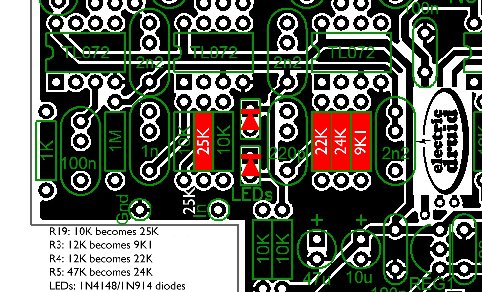
https://electricdruid.net/wp-content/uploads/2021/12/SignalNoiseMod2.png
This includes single silicon diodes, which implies a signal level of about +/-0.6V or 1.2Vpp.
hey tom, sometimes when i set a tempo using the switch, as soon as i strum the tempo come back to the position of the knob, what could be the issue?
Too much level. If the signal going to the digidelay processor overloads it, it can cause it to crash and reset, at which point it boots up again (almost instantly) and loses the tapped tempo.
Make sure the protection diodes you’re using match the set of gain resistors you’ve used.
i’ve used everything from the musikding kit, what should i change?
Sorry, I don’t know because I don’t know what they supplied in the Musikding kit. Email me directly and we’ll work it out.
How would you implement a simple slam switch to momentary drive feedback into self-oscillation when this switch is active?
This is useful for dub mixing.
Is it as simple as adding a momentary switch between 3.3V and CV2 (repeats pin)?
That’d be a good start, but note that depending on the filter settings, you don’t always get oscillation, even with the feedback maxed. This is because the filters can cut away so much of the signal that the level drops below what is required to sustain oscillation.
Of course, it would also be possible to add further feedback in the analog world around the delay.
Point taken regarding the filter setting.
Dug some more about this and on PT2399-based delays, there is often a resistor that limits max feedback (repeats) as a safeguard.
One suggestion (https://www.diystompboxes.com/smfforum/index.php?topic=128387.msg1236001#msg1236001) is to connect a parallel “oscillation” pot resistance across the feedback limiting resistor, in order to be able to first set the level of the oscillation according to taste and then trigger it with momentary switch.
Where in the Digidelay schematic would something like the above be added?
VR2 pot that controls CV1 in your schematic?
Was about to build a PT2399 delay but yours would more interesting/better if it can be modified a bit have a dub slam function.
Also the possibility, as already discussed, to add a sync-in, is another plus.
The situation is different on the DigiDelay since the pots aren’t actually dealing with any audio signals. Instead, they just provide a control voltage to an ADC input. The firmware of the chip then uses that ADC value to adjust the levels internally.
How important is it that 1% resistors are used instead of 5% please, my delay looks good but doesn’t sound quite as it should.
If you’re having problems, I would be very surprised if 5% resistors were the cause. Get in touch and we’ll see what we can find out.
How much is the power consumption of the pedal?
Thanks!
Hi Janne,
Please excuse the delayed reply. The DigiDelay pedal draws roughly 80mA, so it’s not a pedal to run from PP3 batteries!
HTH,
Tom
Wow! This is such a great design and the best delay build I have done yet. It seems everything thing else on the market wether it’s pt3299 or fv-1 has to have modulation on it. This is the one I was waiting for. Easy to follow instructions and I really like the wider spacing for caps so it’s easy to get some mojo going on in it, ie: big ole wimas! The only instruction I deviated from was instead of a tantalum cap I used an organic polymer from nichicon with a super low esr. It was a bit pricey but the pedal is dead quite. The only problem I ran into was the drilling template was way off. Other than that. Perfect. Thanks from South Carolina U.S.A.
Thanks for the feedback, Timothy. I’ll try and find time to check that drill template out if you had trouble with it.
Hi Timothy, any details on where I can grab one of these Nichicon organic polymer caps to try? (e.g. Mouser part number)
Has any one else tried different capacitor and had good luck with results?
I looked at a spectrum of the noise and it appears to spike at
500hz , 1k, 2k, 2.5k, 3k, 4k, and 5k.
Hello,
There is no need to program any code in the 23lc1024 sram?
I’m a bit confused about that…
No, the SRAMs are used as delay memory for the audio going through the circuit. The Digidelay processor chip (dsPIC33FJ64GP802) stores the the firmware in its on-chip Flash program memory.
I’m attempting to use B10k slide faders in place of Level, Rate, and Delay pots.
I had the effect working briefly, but it would stop. It seemed to be having ground issues when placed in enclosure, which I remedied with plastic insulation between pots and pcb.
Currently my big problem is Reg 1 getting awfully hot.
I used LED instead of the diodes in series, should they be the same color? I suspect my ground wiring for the slide faders is causing these issues or I did the leds wrong, in what I suppose is a fault detection area. Is it possible for a diode or capacitor near REG1 to be faulty causing REG1 to heat up so bad? Replace the REG1 Due to damage perhaps?
If it’s getting hot, something is drawing too much current, and that sounds like a short. A bad cap isn’t that likely (possible, bbut not likely) but a short across the pads of some component is quite likely. Alternatively, if you’ve got offboard wiring for the pots, you might have a mistake shorting the 5V and Gnd connections.
First, find the problem and fix it, and then see if the regulator is happier. They’re pretty robust, so it may well have survived.
Hi Tom,
Thanks for publishing the DigiDelay designs and dsPIC code. I am trying to compile the code in MPLAB X IDE v5.30 with the ASM30 v3.31 compiler but getting a ‘make[2]: *** No rule to make target’ error. Any idea what is going wrong? Thank you from Vancouver, Canada. Jan.
Probably Microchip messing about. They dropped support for PIC ASM when they moved to MPLABX 5.0 and made the entirety of the code out there for their chips obsolete, including everything in their own datasheets. I hadn’t realised this affected ASM30 too, but it might have done. I avoided this for the time being by sticking with MPLAB 4.05, but that’s not viable in the longer term.
Thanks for your quick reply Tom. Yes, I had noticed this issue and therefore already use an older version of MPLAB that still supports the MPASM compiler instead of the newer XC ‘upgrade’. I guess it forces programmers to learn the new C compiler language, but it will be major effort to migrate/transcode any existing asm based program. I can try to install an older MPLAB version, and otherwise make an attempt to transcode to the latest XC16..
Thanks for your quick reply Tom. Yes, I had noticed this issue and therefore already use an older version of MPLAB that still supports the MPASM compiler instead of the newer XC ‘upgrade’. I guess it forces programmers to learn the new C compiler language, but it will be major effort to migrate/transcode any existing asm based program. I can try to install an older MPLAB version, and otherwise make an attempt to transcode to the latest XC16..
Hi Tom, great work again.
Any chance you can give me the details of the low and high shelf filters you use in the PIC? I’m looking for the two cut-off frequencies for both filters if possible, the cut-off frequency for the low/high-pass and the cut-off frequency for the low/high-shelf.
Cheers
The cutoff frequencies are changed by the position of the controls, so there isn’t one answer. The knobs don’t control the depth, but rather *where* the cut happens. The cut itself is mild, -3dB IIRC. The thing about a filter on echos like that is that it happens over and over as the echo recirculates, so even a mild cut like that rapidly builds up to be significant.
Thanks for the reply Tom. So the curve of the filter stays the same but the knob position moves the curve up or down the frequency spectrum? Cheers
Exactly! There’s a “FeedbackFilter” coefficient table in the code that is used to set the filter frequencies. It’s 1.15 format, so each number represents a fraction X/32768.
Anyone have a source of low current LEDs? I can’t find any on Tayda (I might just not be finding them though). Everything I find elsewhere is all 20mA. Thanks!
Found some low current LEDs on mouser when I went to buy the DSP and SRAM – facepalm……
Glad you got it sorted, Peter!
Hi,
Finished building the 4 Sec DigiDelay and it sounds great. I really like but have come across a problem. It will power up and sound normal, then suddenly make a huge buzz noise and the delay line will power off and reboot ( i guess). The dry signal will continue but the delay line will shut off and buzz and the LEDs go dark. Unplugging power for a few minutes and reconnecting brings it back but a minute or so late the same thing will happen again. This happens even when the effect is on but no signal is being fed into to the effect. I initially tested without tails and the problem started after i connected the tails jumper but removing tails doesn’t stop it from happening.
I sounds like the rate suddenly being turned to minimum and the repeats to max and self- oscillating.
I’ve done the guitar signal/noise mod rev2 with
R19: 10K becomes 25K
R3: 12K becomes 9KI R4: 12K becomes 22K
R5: 47K becomes 24K
LEDs: IN4148/IN914 diodes
i’ve also tested Germanium 1N60P diodes and suggested in the thread
I also changed LED resistor R23 + R24 to 1k since they were a little too bright at the stock 200R
All my voltages are reading correct.
Any suggestions would be appreciated.
That sounds like the chip is losing power momentarily, or the SRAMs are losing power momentarily. If the LEDs go dark, then the processor is not getting power. If the noise is actual noise (loud hiss) then the SRAMs have lost power and you’re hearing random memory contents. If the noise is a loud “BZZZZ” then there’s something wrong with the comms with the SRAMs, since that happens at a muti-KHz rate.
Is anything hot? Could one of the regulators be shutting down? That might suggest a little short somewhere that’s not enough to shut it right down, but enough to cause overheating problems after it’s been on a while. Drop me a line if you can’t find it and we’ll discuss it more. Good luck!
Hey, thank you for quality PCB and easy-to-follow build docs. I build my effect according guitar level input, but I use hefty amount of gain with fuzz and distortion pedals stacked. I’m noticing there is volume drop using Digidelay in my amps FX loop which is between line and guitar level dB.
I’d like to clear up couple questions about switches. First are trails switch supposed to be latching or momentary? Second I’m not having any effect on tap tempo momentary switch could this be about too hot signal resetting tap tempo to the amount chosen by potentiometer? Does time pot need to be set min or max value for tap tempo to work as it should or should tap override set pot value? I’m also wondering if turning digidelay build to line level version with different resistor values help on volume drop and would it improve tap tempo?
The trails switch should be latching. Yes, too hot a signal will reset the pedal and cause it to jump back to the pot setting, losing any tapped tempo. The time pot doesn’t need to be in any particular position – tap tempo will override the pot position if you tap, and then you have the tapped tempo until you either tap another to move the pot.
The different resistor values alter the *input* level, not the output, so changing to line level mmight help with the tap-tempo-loss problem, but it won’t change the volume drop. For that, you could try decreasing R18 and R19 to 4K7 instead of 10K. That’ll give some gain (x2/+6dB) at the output mixer.
HTH
Got my Delay up and running, sounds pretty awesome! However, I’m working in Eurorack land and would like to permanently implement Momentary bypass and get rid of the Toggle mode, or if that’s not possible just have it stay on. Is it possible to do this by changing the hex file? Cheers!
Hi Jack,
Sorry, I don’t think I follow you. If you don’t want it to toggle on and off, what do you want it to do?
Hi Tom, thanks for replying. I want the behavior it exhibits when pressed for more than 0.5 seconds, i.e. High Voltage = On, Low Voltage = Off to be the behavior at all times, rather than waiting for a rising edge from a momentary switch to toggle On or Off, so as to allow for direct gating and triggering from sequencers and such. Does that make sense?
Oh, I see what you mean now. Thanks. Yes, that’d be possible, but it would involve tweaking the code to hard-wire the momentary mode and remove the possibility of toggling. But if you were using it with a sequencer, you’d rarely need a pulse *less* than 0.5 secs, would you? In which case, you could do it using a pulse stretcher – a classic 555 timer chip application, although something like the 4047 avoids the power rail crowbarring effect the 555 is notorious for.
I really wish youd make my dreams come true and update this to have a reverse mode….
Duly noted. I have been meaning to do a DigiDelay Rev.2 for ages and have tried various approaches, but thus far I’ve never been happy with the results. It’ll happen one day.